
Related Manuals for FOR-A HVS-3800HS


Summary of Contents for FOR-A HVS-3800HS
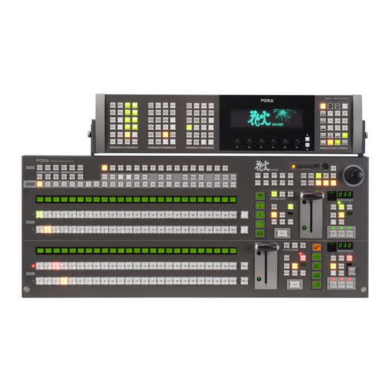
- Page 1 OPERATION MANUAL HVS-3800HS HVS-3800S Digital Video Switcher HVS-16OUA HVS-24OUA HVS-12ROUA Hanabi Operation Unit Edition - Rev. 7...
- Page 2 Edition Revision History Edit. Rev. Date Description Section 2006-12-15 2005-12-05 Added color correction. 2006-08-24 Added HVS-24OUA description. Various additional functions and corrections. 2006-12-22 Addition to OU SETUP-MODE (2/2) menu, USER 15-1-1 button function and Color Mix 15-2 2007-05-31 -Bus selection for User pattern 4-2-1, 10-2 -Side Panel 5-1-7...
-
Page 3: Important Safety Warnings
Precautions Important Safety Warnings [Power] Operate unit only on the specified supply voltage. Caution Disconnect power cord by connector only. Do not pull on cable portion. Do not place or drop heavy or sharp-edged objects on power cord. A damaged cord can cause fire or electrical shock hazards. - Page 4 [Circuitry Access] Do not remove covers, panels, casing, or access circuitry with power applied to the unit! Turn power off and disconnect power cord prior to removal. Internal servicing / adjustment of unit should only be performed by qualified personnel. Do not touch any parts / circuitry with a high heat factor.
- Page 5 Upon Receipt Unpacking The Hanabi series switcher, HVS-3800HS and HVS-3800S, and any of their options you may have purchased are fully inspected and adjusted prior to shipment and can be operated immediately upon completing all required connections and operational settings. Check your received items against the packing lists below.
-
Page 6: Rack Mounting
Check to ensure no damage has occurred during shipment. If damage has occurred, or items are missing, inform your supplier immediately. Rack Mounting The HVS-3800HS/S can be mounted to EIA standard rack units. When rack mounting a unit, remove the rubber feet and use the accessory rack mount brackets (rack ears). -
Page 7: Table Of Contents
Table of Contents 1. Prior to Starting ........................... 1 1-1. Welcome ..........................1 1-2. About HVS-3800 Series Switchers ..................1 1-3. About This Manual ......................2 2. Panel Description ........................3 2-1. Operation Unit ........................3 2-1-1. HVS-16/24OUA ......................3 2-1-2. - Page 8 4-5-1. Returning Menus to Default ..................32 4-5-2. Returning to User Default ..................32 4-6. Parameter Copy ....................... 33 4-7. Copy and Swap ........................ 34 4-7-1. Copying/Swapping Data between M/Es ..............34 4-7-2. Copying/Swapping Data between Blocks ..............35 5. Bus Operation .......................... 37 5-1.
- Page 9 5-10-3. Chromakey Adjustment ................... 70 6. Transition Operations ........................ 72 6-1. Transition Operation Section ..................... 72 6-2. BLACK Transitions ......................73 6-3. Background Transitions ....................73 6-3-1. CUT, MIX, FAM, and NAM Transitions ..............73 6-3-2. WIPE/DVE Pattern Transitions ................. 74 6-3-3.
- Page 10 8. DVE MODIFY ......................... 101 8-1. DVE MODIFY Menu ....................... 101 8-1-1. Re-initializing DVE MODIFY Menu ................. 102 8-2. DVE Effects ........................103 8-2-1. Position and Size ....................103 8-2-2. DVE STILL ......................105 8-2-3. PERSPECTIVE ...................... 105 8-2-4. CROP ........................105 8-2-5.
- Page 11 10-3-3. Deleting User Patterns ..................127 11. Sequence Operation ......................128 11-1. Overview of Sequence Function ................... 128 11-2. Editing Sequences ......................129 11-2-1. Displaying the SEQUENCE Menu ................. 130 11-2-2. Selecting the Sequence Number ................131 11-2-3. PROTCT (PROTECT) Setting (Menu) ..............131 11-2-4.
- Page 12 14-3. Color Correction Flow ....................146 14-4. Assigning A Color Correction Channel ................146 14-5. Proc Amp ........................148 14-6. Color Correction ......................148 14-6-1. Balanced Mode and Differential Mode ..............149 14-6-2. Gamma Curve ...................... 150 14-7. Clip Adjustment ......................151 14-7-1.
- Page 13 16-8-2. Upgrading the DVE Card ..................194 17. Specifications and Dimensions ..................... 196 17-1. System Specifications ....................196 17-1-1. HVS-3800HS (HD Mode) ..................196 17-1-2. HVS-3800HS (SD Mode) / HVS-3800S ..............197 17-1-3. HVS-16/24OUA ..................... 198 17-1-4. HVS-12ROUA ....................... 198 17-2. External Dimensions ..................... 199 17-2-1.
- Page 14 1-8. TRANSITION Menu ......................11 1-9. WIPE PATTERN Menu ..................... 11 1-10. USER PATTERN Menu ....................11 1-11. DVE MODIFY Menu ....................... 12 1-12. WIPE MODIFY Menu ..................... 15 1-13. KEY Menu ........................16 1-14. PREVIEW SELECT Menu ....................18 Appendix 2.
-
Page 15: Prior To Starting
FOR-A provides a wide range of products, from basic support units to complex system controllers, which have been increasingly joined by products for computer video based systems. Whatever your needs, talk to your FOR-A representative. We will do our best to be of continuing service to you. -
Page 16: About This Manual
MIX, FAM and NAM transitions available with 100 WIPE preset patterns in standard configuration, expandable to 120 DVE preset patterns including options. Versatile 4 channel (for SDTV) or 2-channel (for HDTV) DVE modify operations possible with optional DVE board. ... -
Page 17: Panel Description
2. Panel Description 2-1. Operation Unit 2-1-1. HVS-16/24OUA Control Panel DIGITAL VIDE O SWITCHER TRANS TRANS USER KEY1 KEY2 KEY3 KEY1 KEY2 KEY3 EVENT SETUP MATT BKGD BKGD PATT WARP EDGE WIPE MATT MATT MATT WIPE MATT MATT MATT STILL SETUP PATT... -
Page 18: Hvs-12Roua
2-1-2. HVS-12ROUA Control Panel DIGITAL VIDEO SWITCHER TRANS WIPE USER WIPE/DVE EVENT STATUS SETUP PATT PATT BKGD MODIFY M/E1 KEY1 KEY2 KEY3 SETUP I N C DVE-PGM DVE-KEY1 PLAY TRANS WIPE WIPE/DVE FUNC BKGD PATT MODIFY DVE-PST DVE-KEY2 PAU SE M/E2 FILE KEY1... -
Page 19: Main Unit
(To open the STATUS menu, press the STATUS button in the menu section.). Then power the unit off and contact your FOR-A supplier for advice. If you have both the accessory and optional power supplies installed, you will need to turn at least one power switch ON before you can use your MU. -
Page 20: Rear Panel
2-2-2. Rear Panel EDIT O R G PI/T ALLY OU T G PI IN LAN 1 AR CNET R S-422 (10/ 100BAS E-T ) ALAR M T RI SYNC IN BB IN R EF OU T RATING LABEL R S-422 INPUT PREV CLEAN... -
Page 21: Interfaces
9-pin D-sub connector (male) with inch security lock screws needed for user cable fabrication. Fan alarm Pins 1, 6 remain OPEN during normal operation. If fan failure occurs at HVS-3800HS/S side, pins 1, 6 will short and fan alarm signal output occurs. Power supply alarm Pins 2, 7 remain OPEN during normal operation. - Page 22 EDITOR Connector Pin Assignment Table (9-pin D-sub, female) Pin No. Signal Name Description Frame ground Transmit data (-) Receive data (+) Signal ground Not used Signal ground Transmit data (+) Receive data (-) Frame ground Cable Connectors 9-pin D-sub connector (male) with inch security lock screws needed for user cable fabrication.
- Page 23 Pin1 to 10 signal assignments shown above are factory default settings. These can be changed in operational menus. See section 16-1-1. “GPI IN Free Assignments” for more details. Circuit Switch or Relay Open corrector External Device HVS-3800HS/S External Device HVS-3800HS/S...
- Page 24 GPI/TALLY OUT Connector Pin Assignment Table (25-pin D-sub female) Pin No. Description M/E1-BKGD TRANSITION (default setting) M/E1-KEY1 TRANSITION (default setting) M/E1-KEY2 TRANSITION (default setting) M/E1-KEY3 TRANSITION (default setting) M/E2-BKGD TRANSITION (default setting) M/E2-KEY1 TRANSITION (default setting) M/E2-KEY2 TRANSITION (default setting) M/E2-KEY3 TRANSITION (default setting) Not assigned (default setting) Not assigned (default setting)
- Page 25 HVS-3800HS/S External Device Circuit Max voltage: 40V Max load current: 100mA...
-
Page 26: Mu Rear Panel Cards
IMPORTANT Before touching the cards and other components inside the HVS-3800HS/S, be sure to turn off the Power switch of the MU and disconnect the front panel and rear unit to prevent electric shock. If the MU case needs to be opened to make settings or adjustments, be sure that the work is performed by an experienced technician, or contact your FOR-A supplier. - Page 27 MU REAR 1-4 (Rear bottom fans 1-4) IMPORTANT HVS-38UC/DC/AUMV/SS/SSAM requires card expansion for both the front panel and rear panel sides. For details about expansion with optional cards and optional power supply units or fan replacement, please contact your FOR-A supplier.
-
Page 28: System Configuration
3. System Configuration 3-1. Basic Configuration (75ohm terminator) REF OUT TRI SYNC REF OUT M/E1 PGM output Camera M/E1PGM IN 1 PREV output M/E1PREV IN 2 CLEAN output M/E1CLN Character IN 3 generator | M/E2 IN 14 PGM output M/E2PGM Digital video IN 15 PREV output... -
Page 29: Optional Configuration
3-2. Optional Configuration (75ohm terminator) Multi-viewer REF OUT REF OUT SYNC IN VTR/DDR M/E1 M/E1PGM PGM output IN 1 M/E1PREV PREV output IN 2 M/E1CLN CLEAN output VTR/DDR IN 3 M/E2 M/E2PGM PGM output Character M/E2PREV PREV output generator M/E2CLN CLEAN output |N 26 Character... -
Page 30: Power Related Information
3-3. Power Related Information Before powering ON your Hanabi series switcher, verify all cabling connections are secure and power connections are in place. 3-3-1. Starting OU (Operation Unit) Use the supplied AC cord to connect the OU to AC power supply. ... -
Page 31: Selecting Aspect And Format
3-4. Selecting Aspect and Format Before using your Hanabi switcher, you will have to select the aspect ratio and signal format needed based on your operational system. MU SETUP button on the control panel should be flashing red at power ON. Press MU SETUP button while it’s flashing red to access MU SETUP-SYSTEM menu shown below. -
Page 32: Menu Operations
4. Menu Operations Menus shown in the display are used to make settings that effect how your HVS-3800 series MU responds and performs during operations. The following sections tell you how to access and change operational parameters in the menu displays 4-1. -
Page 33: Making Settings (Hvs-16/24Oua)
4-2. Making Settings (HVS-16/24OUA) 4-2-1. Selecting Needed Menu To display a menu, press the button for the desired menu in the menu section (A on the section 4-1) besides the display. To move between menu pages, use the UP and DOWN buttons at the right of the controls. -
Page 34: Changing Parameter Values
4-2-2. Changing Parameter Values The menu page is divided into two rows above and below and six horizontal blocks. Up to six parameters can be displayed in one row. To change a parameter, turn the control F1 to F6 that is directly below the block. Parameters can be changed for the row that is selected (cursor bar is displayed). -
Page 35: Confirmation Needed Parameters
4-2-3. Confirmation Needed Parameters In the parameters below, the value must be confirmed by pressing a function control below each parameter. Parameter Menu Parameter Menu REBOOT MU SETUP top STILL1-6 STILL INIT MU SETUP-SYSTEM DVE STILL STILL OU INIT OU SETUP- MODE 4-2-4. -
Page 36: Joystick Input
4-2-5. Joystick Input You can also use the joystick for making settings in menus. The general procedures for making and changing operational menu settings using a joystick are as follows. The X, Y, and Z axes of the joystick are used to change three parameters at once. X-axis Move the joystick to the right or left. -
Page 37: Making Settings (Hvs-12Roua)
4-3. Making Settings (HVS-12ROUA) 4-3-1. Selecting Needed Menu To display a menu, press the button for the desired menu in the menu section (A on the section 4-1) besides the display. To move between menu pages, use the UP and DOWN buttons at the right of the controls. -
Page 38: Changing Parameter Values
4-3-2. Changing Parameter Values The menu page is divided into two rows above and below and six horizontal blocks. Up to six parameters can be displayed in one row. To change a parameter, turn the control F1 to F6 that is directly below the block. Parameters can be changed for the row that is selected (cursor bar is displayed). -
Page 39: Confirmation Needed Parameters
4-3-3. Confirmation Needed Parameters In the parameters below, the value must be confirmed by pressing a function control below each parameter. Parameter Menu Parameter Menu REBOOT MU SETUP top STILL1-6 STILL INIT MU SETUP-SYSTEM DVE STILL STILL OU INIT OU SETUP- MODE 4-3-4. -
Page 40: Joystick Input
4-3-5. Joystick Input You can also use the joystick for making settings in menus. The general procedures for making and changing operational menu settings using a joystick are as follows. The X, Y, and Z axes of the joystick are used to change three parameters at once. X-axis Move the joystick to the right or left. -
Page 41: Displaying Menus
4-4. Displaying Menus 4-4-1. Menu Buttons (HVS-16/24OUA) To display a menu, press the button for the desired menu in the menu section (SYSTEM, M/E1, M/E2). MODIFY menu buttons DVE bus selection buttons TRANS TRANS KEY1 KEY2 KEY3 KEY1 KEY2 KEY3 BKGD SETUP MATT... - Page 42 When the DVE MODIFY menu is displayed, first press the DVE bus selection button (DVE PGM, DVE PST, DVE KEY1, DVE KEY2, or DVE KEY3 button) in the M/E1(M/E2) section so that it lights orange, and then select the applicable bus. Next, press one of the buttons below to display the menu.
-
Page 43: Menu Buttons (Hvs-12Roua)
4-4-2. Menu Buttons (HVS-12ROUA) To display a menu, press the button for the desired menu in the menu section SYSTEM group M/E1 group STATUS button TRANS WIPE USER WIPE/DVE EVENT STATUS SETUP PATT PATT MODIFY BKGD M/E1 KEY1 KEY2 KEY3 SETUP DVE-PGM I N C... -
Page 44: Menu Access Shortcuts
4-4-3. Menu Access Shortcuts Double-clicking the following buttons in the bus section and transition section displays the respective menu. Button Section containing button Opened menu * MATT1, MATT2 M/E1, M/E2, AUX/KEY bus sections MATT * STILL1 to STILL4 M/E1, M/E2, AUX/KEY bus sections STILL STILL5 to STILL6(option) MIX, WIPE, FAM, NAM, CUT... -
Page 45: Returning To Default
4-5. Returning to Default Press and hold the related F1 to F6 control to return to factory default settings. Press and hold Control F1 - F6 Using the joystick to return to the factory default settings HVS-16/24OUA Display the menu settings that will be returned to their defaults. ... -
Page 46: Returning Menus To Default
WIPE MODIFY(1/3) JOYSTICK POSITION MULTI ANGLE MENU MENU WIPE ASPECT SOFT EFFECT TYPE LEVEL INVERT Cursor bar Changes can be made for the X, Y, and Z buttons that are lit only. IMPORTANT Holding down the DEF button when the WIPE POS or DVE ROT button is lit returns all of the WIPE MODIFY data or DVE MODIFY data to their factory default settings. -
Page 47: Parameter Copy
4-6. Parameter Copy Values set for items in menus can be easily copied. Up to six settings can be stored in the copy buffer. Parameter copy operation (Copying the MASK parameter value in the M/E1-KEY1 menu to M/E2-KEY1) Open the menu (M/E1 - KEY1 - MATT MASK menu) from which an item is to be copied. -
Page 48: Copy And Swap
4-7. Copy and Swap The M/E2 settings can be easily copied (COPY) or swapped (SWAP) to M/E1, or all the values in the KEY menu can easily be copied or swapped to another key menu. TIPS If the settings are mistakenly changed by a copying or swapping operation, use the data recovery function to return to the previous settings. -
Page 49: Copying/Swapping Data Between Blocks
With the panel in this condition, press COPY button to copy the currently made M/E2 signal settings to M/E1. (Settings in M/E1 and M/E 2 menus should be the same after copy operation is complete.) If you press the SWAP(PASTE) button, M/E2 settings become M/E1 settings and M/E1 settings become M/E2 settings. - Page 50 The setting can be made for copying or swapping the crosspoint information for the menu button that is lit. Set to OFF if no copying will be performed. (If one of the settings is set to OFF, the crosspoint information will not be copied or swapped.) COPY SWAP(1/1) M/E1-XPT...
-
Page 51: Bus Operation
5. Bus Operation 5-1. Selecting the Video Source 5-1-1. Bus Button Sections The video signals input to the switcher are assigned to the bus buttons on the control panel for usage. The assigned signals are shared by the M/E1 bus section, M/E2 bus section, and AUX/KEY bus section. -
Page 52: Shift Button
5-1-2. SHIFT Button SHIFT + button When the SHIFT button is used, two signals can be assigned to a single bus button. The SHIFT button is not provided in the factory default settings. To use the SHIFT button, use the bus button assignment procedure to assign a SHIFT function to a bus button. - Page 53 When Set to Toggle: When the SHIFT button is off, buses 1-16 can be selected. MATT M/E1 Pressing 2 selects bus 2 and lights the button. M/E 2 2 2 2 MATT M/E1 Pressing 1 selects bus 1 and lights the button. To select using the SHIFT+ button operation, press the bus button while holding down the SHIFT button.
-
Page 54: Flip-Flop
5-1-3. Flip-Flop HVS-3800 series OUs are provided with two M/Es, and each of which has a PGM (current out) and a PST (next out) background signal selection bus rows. The factory default setting for M/E switchover response is a flip-flop type. If you need a non flip-flop type bus response, you can change the M/E signal button response so that it cues the operator when the A/B bus switchover occurs. -
Page 55: Changing The Signal Name
5-1-5. Changing the Signal Name Video signals that can be assigned to the M/E bus are video signals input from the MU rear panel, STILL1 to 6, MATT1, MATT2, BLACK, WHITE, and color bar internal signals. Any names can be assigned to these signals. In the default settings, for instance, video input 1 from the rear panel is set as IN01. -
Page 56: Bus Signal Assignment And Inhibit Settings
5-1-6. Bus Signal Assignment and Inhibit Settings Video signals that can be assigned to the M/E bus are video signals input from the MU rear panel, STILL1 to 6, MATT1, MATT2, BLACK, WHITE, and color bar internal signals. Follow the procedure below to assign video signals to the bus. ... -
Page 57: Adding Side Panel Images
5-1-7. Adding Side Panel Images Side panel images can be added to the background video only when the primary inputs (IN01 to IN28) or the stills (STILL1 to STILL6) are assigned to the background. Note that the side panel feature does not support all available signal standards. See the table below. -
Page 58: Bus Matt
5-2. BUS MATT Matt signals can be used in a variety of ways in the HVS-3800 series. Two different matt signals can be assigned to the M/E bus. Also, matt signals are used for the insert signal, edge, and shadow of the keyer. The color of these matt signals can also be set in the respective KEY menu, but they can also be set together in the BUS MATT menu. - Page 59 Color Picker The color picker allows you to pick any color on the screen to be used for matt colors. To use the color picker, proceed as follows. Press the DOWN button in the MATT menu to display the MATT-COLOR PICK menu. MATT(3/3) COLOR PICK 66.3...
-
Page 60: Gradation Matt
5-3. Gradation Matt The gradation matts can be used for the border colors or key insert (key fill), and they can be adjusted in the GRADATION MATT submenu of the FUNCTION menu. Assignable buses The gradation matts can be assigned to the following buses: WIPE BORDER KEY INSERT AUX7 - 10... -
Page 61: Stills
5-4. Stills Up to 4 stills (STILL1 to 4) can be stored to the still memory at the standard configuration. Two more stills (STILL5 to 6) can be used when the HVS-38SS option is installed to the switcher. Stills can be assigned to the background bus and auxiliary bus. They are stored in the following way. -
Page 62: Selecting Where Outputs Appear
5-5. Selecting Where Outputs Appear 5-5-1. Output Connector The output connectors for the video signals of the main unit rear panel have the configuration shown below. ED ITOR GPI/T ALLY OUT GPI IN LAN 1 ARCNET RS-422 (10/100BASE-T) ALARM T RI SYNC IN BB IN REF OUT RS-422... -
Page 63: Selecting Preview Output
5-5-2. Selecting Preview Output The outputs from M/E1PREV and M/E2PREV connectors are the previews for M/E1 and M/E2 and their signals can be selected in the menu respectively. Select the output signals of the preview as shown in the procedure below. ... - Page 64 HVS-12ROUA Select the output target. M/E1 M/E1 M/E1 SHIFT KEY1 KEY2 KEY3 2/10 3/11 4/12 5/13 6/14 7/15 8/16 SELECT Select the M/E2 M/E2 M/E2 M/E1 M/E1 M/E1 M/E2 M/E2 M/E2 KEY1 KEY2 KEY3 OUT A OUT B PREV CLEAN PREV CLEAN output signal.
- Page 65 Press the DOWN button again to move to the bottom page, and then select the key output signal in the KEY OUT A and KEY OUT B items. Press the ENTER button in the keypad to confirm the selection. MU SETUP OUTPUT(2/2) CLEAN OUT...
-
Page 66: Aux Link
5-5-4. AUX LINK In the AUX-LINK function, the auxiliary outputs are grouped, and the master and slave outputs are set so all slave output signals can be switched simultaneously by simply selecting the master output signal. A group consists of one master output and up to four slave outputs. Five auxiliary output groups can be set. - Page 67 Creating Signal Link Groups Press the UP button to go back to the AUX LINK menu. In the AUX LINK menu turn F1 to select LINK GROUP under SELECT. Press F1 or the DOWN button to display the AUX LINK - LINK GROUP submenu.
-
Page 68: Setting Up Stereoscopic 3D Input/Output
It outputs an L/R pair of Stereoscopic 3D from AUX1 (M/E2 PGM) and AUX2 (M/E1 PGM). IN01 is assigned to Bus Button 1 and IN03 to Bus Button 3. It switches the output video between 2 pairs by pressing a bus button on the M/E2. HVS-3800HS L video IN01... - Page 69 Enabling Stereo 3D mode Turn F2 in the [AUX LINK] menu to select S3D. Once the Stereo 3D mode is enabled, the FUNCTION button blinks red. FUNCTION AUX LINK 1. AUX GROUP 2. LINK GROUP SELECT ENABLE Enabling Stereo 3D mode After having done the above settings, pressing Button 1 on the M/E2 PGM row outputs the L/R video, IN01 and IN02 (IN03 and IN04), respectively from AUX1 and AUX2.
-
Page 70: Key Setup
5-6. Key Setup Keys are additional signal layers you can composite over the M/E background signal. Standard keys are basically created by inserting part of one picture into another to create a composite signal result as the figure below. Background Background + Key Cut Key Cut Background + Key... -
Page 71: Key Menu
5-6-1. Key Menu Displaying Keyer Menu The key menus are displayed using the buttons shown HVS-12ROUA in the figures below in the M/E1 group and M/E2 group (HVS-16/24OUA)or opening keyer submenus from each keyer top menu (HVS-12ROUA). TRANS WIPE WIPE/DVE SETUP PATT... -
Page 72: Returning Key Menus To Default Settings
5-6-2. Returning Key Menus to Default Settings The key menus can be returned to their default settings by holding down the menu button for the respective key. When the button is held down, a long beeping sound is made, and the selected menu parameters are returned to their defaults. -
Page 73: Selecting The Key Source / Insert (Hvs-16Oua)
5-6-4. Selecting the Key Source / Insert (HVS-16OUA) The key signal is selected using the key bus select button and AUX/KEY button. It can also be selected from the KEY-SOURCE / INSERT menu. This example describes when the bus button 1 (IN01 signal) is selected for KEY SOURCE (key signal) and bus button 13 (STILL1 signal) is selected for KEY INSERT (fill signal) in KEY1 of M/E1. -
Page 74: Selecting The Key Source / Insert (Hvs-24Oua)
5-6-5. Selecting the Key Source / Insert (HVS-24OUA) The key signal is selected using the key bus select button and AUX/KEY button. It can also be selected from the KEY-SOURCE / INSERT menu. This example describes when the bus button 1 (IN01 signal) is selected for KEY SOURCE (key signal) and bus button 13 (STILL1 signal) is selected for KEY INSERT (fill signal) in KEY1 of M/E1. -
Page 75: Selecting The Key Source / Insert (Hvs-12Roua)
5-6-6. Selecting the Key Source / Insert (HVS-12ROUA) The key signal is selected using the key bus select button and AUX/KEY button. It can also be selected from the KEY-SOURCE / INSERT menu. This example describes when the bus button 1 (IN01 signal) is selected for KEY SOURCE (key signal) and bus button 11 (STILL1 signal) is selected for KEY INSERT (fill signal) in KEY1 of M/E1. -
Page 76: Key Link
5-6-7. Key Link When the key link function is set to ON, the key source signal and key insert signal are linked to form a pair. When the key source signal and key insert signal are selected, they are automatically registered as a pair. Also, if a key insert signal only is selected, then a key source signal is automatically selected to pair with it. -
Page 77: Key Matt
5-6-9. KEY MATT In addition to the MATT1 and MATT2 bus matt signals, a matte signal dedicated to keys (KEY MATT) can also be used. The color for the KEY MATT signal can be setup in each keyer menu using the procedure below. ... -
Page 78: Key Adjustments
5-7. Key Adjustments How the key and background video are mixed together is adjusted using the parameters below. KEY1(1/6) SOURCE/INSERT INSERT SOURCE TYPE TYPE SIGNAL SIGNAL INVERT IN01 IN02 KEY SIGNAL TRANSITION GAIN CLIP TRANSP RATE LIMIT LEVEL 100.0 FAM (KEY-SOURCE/INSERT menu) When this is set to ON, the keys are combined using an additive mix. -
Page 79: Key Mask And Invert
RIGHT BOX Mask The HVS-3800HS/S has a box mask function that can be used to hide parts of the key that fall outside the mask area. There is also an invert function that will cause parts of the key inside the mask area to be hidden if that is what you need. - Page 80 KEY3 Mask The procedure for using KEY3 as a mask is almost the same as when setting up a regular key box mask. Also, the KEY3 mask can be inverted to hide the inside of the KEY3 image. Parameter Setting Description The entire KEY3 mask area is set to background image.
-
Page 81: Edge And Shadow
5-9. Edge and Shadow A colored edge and / or shadow can be added to KEY1 and KEY2. Key w/o edge or shadow Normal edge Outline edge Shadow 5-9-1. Edge The edge application lets you adjust edge width, softness level, transparency and color. Outline is also possible in the edge settings. -
Page 82: Chromakeys
5-10. Chromakeys 5-10-1. Chromakey Setup Flow Chromakeys differ from regular keys in that the key is cut based on ignoring a certain color rather than signal levels. For example, if blue (the normally used back drop color in chromakey studios) is used, all blue areas in the source video are removed and video (CG or other picture) can be inserted to the areas where the blue previously appeared. -
Page 83: Auto Chromakey Setup
5-10-2. Auto Chromakey Setup Press a desired bus button in the PGM/PST bus section to select a background image. Press KEY1 button in the BUS SELECT section. Then press a bus button in the AUX/KEY bus section to select the Key Insert/Source pair signals for KEY1 using the Key Link function. -
Page 84: Chromakey Adjustment
KEY1(5/6) AUTO CHROMA KEY POSITION SELECT PGMOUT CURSOR SIZE CHROMA KEY EDGE LEFT RIGHT Move the joystick counter-clockwise with the Z button in the joystick lit to make a chromakey. Once the joystick is moved counter-clockwise, cursor selected color should be ignored and a chromakey should be automatically composited with background on the preview line output. - Page 85 Chroma Angle This determines the width of the color hue ignored by the ANGLE option. If the ignored color is not uniform, this angle should be adjusted to a wide setting. The ignored color is fine adjusted using the Y, C, and K options in ANGLE OFFSET. KEY1(6/6) MANUAL CHROMA KEY MANUAL ADJUST...
-
Page 86: Transition Operations
6. Transition Operations The following transition features are available in this switcher: Black transitions (only M/E2) Background CUT, MIX, NAM, FAM, WIPE (DVE) transitions KEY1, KEY2 and KEY3 CUT, MIX (Normal, FAM and NAM) and WIPE (DVE) transitions ... -
Page 87: Black Transitions
IMPORTANT The transitions are always performed simultaneously (TIE transitions) when selecting the background and keyer(s) at the same time for transition in HVS-12ROUA. In HVS-16/24OUA, Simultaneous (TIE) transitions can be performed only when the TIE transition setup is made. This section presents examples of transition operation using M/E2. Operation with M/E1 is almost identical. -
Page 88: Wipe/Dve Pattern Transitions
6-3-2. WIPE/DVE Pattern Transitions In WIPE transitions and DVE transitions, preset patterns need to be selected. The patterns that can be selected in the transition section are the five types displayed on the five pattern buttons. The WIPE/DVE pattern transitions are executed using the procedure below. ... -
Page 89: Background Preview
6-3-3. Background Preview The TRANS PREV button in the transition section can be used to check the background transition using PREV output. In this example, we set a WIPE/DVE transition, and check the next transition. Press the WIPE button to light it. Press the BKGD button to light it. Press a pattern button to select a pattern. -
Page 90: Key Transitions
6-4. Key Transitions The key transition operation is described here using the M/E2 KEY1. When a fill signal and key signal are input to IN01 and IN02 of the MU rear panel, the keys are set as shown below. Press the KEY1 button in the M/E2 group of the menu section to display the KEY1 menu. -
Page 91: Fam And Nam Transitions For Keyers
6-4-1. FAM and NAM Transitions for Keyers The FAM and NAM transitions for keyers are available with menu setting. ( The hardware version for M/E1 and M/E2 must be 02-00 or higher. ) Making FAM and NAM Transitions Available Change the KEYER FAM/NAM item in the OU SETUP - MODE (2/2) menu from DISBLE (DISABLE) to ENABLE. -
Page 92: Key Preview
6-4-3. Key Preview Confirmation of key setup and transitions are performed using the procedure below. Signal confirmation <HVS-16OUA/12ROUA> To confirm the KEY1 setup in M/E1, press M/E1KEY1 in the BUS SELECT section to light up the key insert (fill) signal on the AUX/KEY bus section. Press M/E1KEY1 (with SHIFT lit) to light up the key source signal on the AUX/KEY bus section. - Page 93 <HVS-12ROUA> When the ON lamp above the KEY1, KEY2, or KEY3 is lit, the signal is on-air. WIPE DIRECTION TRANSITION RATE BKGD FADER BKGD TRANS FADER LIMIT KEY1 PREV LIMIT KEY1 KEY2 WIPE DIRECTION KEY2 KEY3 TRANSITION RATE KEY3 TRANS BKGD KEY1 KEY2...
-
Page 94: Simultaneous (Tie) Transitions
6-5. Simultaneous (TIE) Transitions IMPORTANT The transitions are always performed simultaneously (TIE transitions) when selecting the background and keyer(s) at the same time for transition in HVS-12ROUA. In HVS-16/24OUA, Simultaneous (TIE) transitions can be performed only when the TIE transition setup is made. This section presents examples of transition operation using M/E2. -
Page 95: Selecting The Pattern
6-6. Selecting the Pattern The pattern transition can be executed simultaneously for multiple buses. In this case a pattern must be set for each bus before execution of the transition. This section describes the procedure for selecting the pattern. 6-6-1. Selecting the Pattern ... -
Page 96: Pattern Confirmation
WIPE PATTERN SELECT BKGD KEY2 WIPE KEY1 LIST Turn F6 to display another group. The pattern block display in the transition section is also switched at the same time. Turning F1 - F5 enables display (storage) of different patterns. Patterns used in other transitions are also selected in the same way. IMPORTANT Note that only one WIPE pattern can be selected at a time, and so if the WIPE pattern is changed in another transition, the WIPE pattern in the previously-selected transition... -
Page 97: Wipe Pattern Modify
6-7. WIPE Pattern Modify The WIPE preset pattern can be modified. The preset pattern can be changed by selecting the pattern and then modifying it with the MODIFY menu. To modify a pattern, select it in the transition section. 6-7-1. Opening the WIPE MODIFY Menu ... -
Page 98: Wipe Modify Menu
6-7-2. WIPE MODIFY Menu When modifying a WIPE pattern, changes can be made to the WIPE position or movement angle, multi-wipe, aspect ratio, edges, borders, and mosaic and other subeffects. The parameters that can be set are shown in the table below. Menu Menu Description (Setting) -
Page 99: Re-Initializing Wipe Modify Menu
6-7-3. Re-initializing WIPE MODIFY Menu The WIPE MODIFY menu can be returned to the default settings using one of the following ways. Removing the modified preset patterns from the menu Use the WIPE PATTERN menu or PATTERN SELECT menu to remove the modified patterns from the WIPE PATTERN list (5 groups of 25 total patterns). -
Page 100: Dve Pattern Modify
6-8. DVE Pattern Modify The DVE preset patterns can be modified. To modify a pattern, select the pattern in the transition section, and then set the modifier in the DVE MODIFY menu. 6-8-1. Opening the DVE MODIFY Menu Press the WIPE button in the M/E2 (or M/E1) BKGD transition section or KEY transition section to turn on the button light. -
Page 101: Channels And Keyframes
On the WIPE PATTERN menu, the letter "M" is added in front of the number of the DVE pattern for which a modify setting has been performed. Similarly, the letter "M" is added to the icon on the pattern block of the transition section. This modify pattern can be used in the same way as a preset pattern. -
Page 102: Other Transition Settings
6-9. Other Transition Settings 6-9-1. Transition Rate The transition rate setting determines how long your transition takes in picture frames to electrically complete. (Factory default is 30 frames.) Press the TRANS/BKGD button to display the TRANS(1/2) menu. Change the AUTO TRANS RATE value. Check the transition rate display shown above the AUTO button. -
Page 103: Fader Limit (Transition Limit)
6-9-2. Fader Limit (Transition Limit) The fader limit setting determines how far your transition does or does not proceed electrically. When performing transitions (mix or other) there may be times when you want the transition to the next signal to only complete to a certain degree instead of fully switching from one picture to another. -
Page 104: Fader Insensitive Region
Offset for Fader Lever The offset for the fader lever can be adjusted in the FADER item on the OU SETUP - FADER menu. It is also possible to enable the fader's TIE function (refer to section 6-5. "Simultaneous (TIE) Transitions"). Parameter Description Default... -
Page 105: Auto Button Operational Setting
6-9-5. AUTO Button Operational Setting The AUTO transition behavior when the AUTO button is pressed again during transition can be selected among the following three types. The operation performed when the AUTO button is pressed during an AUTO transition is changed. Operate as follows. ... -
Page 106: Dve Patterns And Number Of Channels
6-9-8. DVE patterns and number of channels Operation for transitions using DVE patterns is the same as for transitions using WIPE patterns, though different patterns can be used by a multiple number of buses with the former. However, the number of buses available for transitions simultaneously is restricted by the DVE channels which can be used. -
Page 107: Dve Transition Additional Settings
6-9-9. DVE Transition Additional Settings When DVE patterns are used, transition direction, endpoint processing, crop and other additional settings can be performed. Perform these settings on the sub menus of the FUNCTION menu and the DVE SETUP sub menu. Press the FUNC button in the SYSTEM group of the menu section to display the FUNCTION - DVE SETUP menu. -
Page 108: Dve Tally
6-9-10. DVE Tally The DVE tally feature allows you to light up a bus button or add DVE tally information to a tally output. For example, the button light of the M/E2PST bus turns red when shrinking the M/E2PGM image to see the M/E2PST image behind the M/E2PGM by using the LINE DVE, if the feature is enabled. -
Page 109: Line Dve
7. LINE DVE LINE DVE is a setting that applies DVE effects to an individual bus and uses reduce, enlarge, rotation, lighting, and other operations to allow modification of the video for that bus. It can also apply the effects to the PGM, PST, KEY1, KEY2 and KEY3 buses of M/E1 and M/E2. There are two setting methods. -
Page 110: Opening The Dve Modify Menu
7-1-2. Opening the DVE MODIFY menu To Open DVE MODIFY menu for M/E2PGM Bus In this procedure example, assume that the DVE ON/OFF function has been assigned to bus button 1 . To apply the M/E2PGM bus to LINE DVE, press bus button 1 on the PGM bus to turn PGM LINE DVE to ON. - Page 111 KEY1, KEY2 and KEY3 The settings are performed in the same way for KEY1, KEY2 and KEY3 as well. Press the DVE KEY1, DVE KEY2 and DVE KEY3 buttons respectively to light them up orange and open the DVE MODIFY menu. IMPORTANT When there are no free DVE channels, the LINE DVE function is not available, and the buttons will not light even if they are pressed.
-
Page 112: Using The User Buttons
7-2. Using the USER Buttons This section uses the USER buttons to illustrate the assignment procedure of the LINE DVE ON/OFF functions of the M/E2PGM bus, M/E2PST bus and M/E2KEY1 bus. Setting will be as follows. 7-2-1. Setting the LINE DVE ON/OFF Function Buttons ... - Page 113 Press the DVE PGM button in the M/E2 group of the menu section. The DVE PGM button now lights up orange. At the same time, the DVE MODIFY menu for the PGM bus is opened, and LINE DVE modify operations are enabled. ...
-
Page 114: Line Dve Modify Setting Example
7-3. LINE DVE Modify Setting Example This section uses the example of setting the M/E2PGM bus to LINE DVE and reducing the PGM image to illustrate the LINE DVE modify setting procedure. Set the DVE function of the M/E2PGM bus to ON. ... -
Page 115: Dve Modify
8. DVE MODIFY The HVS-3800HS/S uses the DVE MODIFY menu to set what kind of effects are to be applied using the LINE DVE function. The DVE preset patterns themselves can be modified also using the DVE MODIFY menu. This chapter describes the modify effects which can be used for DVE and provides details on the DVE MODIFY menu. -
Page 116: Re-Initializing Dve Modify Menu
Menu Menu Description Reference/Note Menu button button NEGA Sets polarization effect. 8-2-8 8-2-8 MOSAIC Sets mosaic effect. Unable to use with MULTI warp type. Sets resolution for PAINT Y-Lv, C-Lv, Y/C-Lv luminance / chrominance EFFECT SELECT, DEFOCUS LEVEL (H-Lv, V-Lv, Sets defocus effect. -
Page 117: Dve Effects
8-2. DVE Effects 8-2-1. Position and Size DVE MODIFY(1/8) DVE STILL LINE STORE BACK GLOBAL POSITION POSITION SIZE 1000 1000 1000 About POSITION: POSITION simply moves the picture to a different location in the effects space without changing size or effect spatial references. The examples below represent image positioning results when GLOBAL POSITION and LOCAL POSITION parameters are both set to default (0, 0, 0). - Page 118 About ROTATION: GLOBAL ROTATION defines the relationship between the image and the 3D effects space axial coordinates during image rotation in the space. It rotates the image around the center of the POSITION. LOCAL ROTATION defines the relationship between the image and its axial coordinates during image rotation operations and is unrelated to global movement within the 3D effects space.
-
Page 119: Dve Still
8-2-2. DVE STILL The DVE STILL is used to save an image for DVE-specific still. This image can be applied to back side of the DVE image such as the reverse page of page turn effects or the side walls of PIZZA BOX. -
Page 120: Warp (Option)
8-2-5. WARP (Option) Parameter Range Description See "About TYPE" table * TYPE Selects the type of DVE effect applied to the pattern. following. LEVEL OFF, -7999-7999 See "About TYPE" table following. WARP OFF, -7999-7999 See "About TYPE" table following. 0-7999 See "About TYPE"... -
Page 121: Border
8-2-6. BORDER DVE MODIFY(5/8) BORDER EDGE SELECT OUTSIDE SOFT BORDER SOFT INSIDE The figures below show examples of the DVE image with and without border effect applied. If applied, inner border and outer edge softness can be adjusted. Line Parameter Description EDGE SOFT Sets border outside softness. -
Page 122: Trail / Border Color / Mono Color
8-2-7. TRAIL / BORDER COLOR / MONO COLOR SHADOW/TRAIL DVE MODIFY(6/8) BORDER COLOR TRAIL TYPE LENGTH MONO COLOR ENABLE Parameter Description TYPE Sets trail effect types TRAIL LENGTH Sets trail length if TRAIL ON. BORDER COLOR SAT, LUM, HUE Sets border color ENABLE Sets monochrome color effect ON/OFF. -
Page 123: Hilite/Shadow
DEFOCUS : Gives the image an out-of-focus look. Defocus level can be set. MOSAIC : Creates a mosaic effect. Mosaic cell size can be changed using the level setting. FREEZE : Freezes the image. Frame freeze and field freeze are available. STROBE RATE : Makes the image look like it was filmed with a strobe light on. - Page 124 WARP HILITE SPOT WIDTH POS-X POS-Y TYPE TYPE WAVE ACCORD RIPPLE 0 to -100.0 to AUTO - - - - Page roll and 100.0 100.0 page turn types 0 to -100.0 to FLAT - - - - 100.0 100.0 PIZZA -100.0 to -100.0 to FLAT...
-
Page 125: Examples Of Effect Operations
9. Examples of Effect Operations Besides the WIPE and DVE preset patterns, the HVS-3800HS/S also provides menus and tools that add a wide variety of effects to video. This section shows examples of some typical effects using these tools. 9-1. Effects using WIPE Modify 9-1-1. -
Page 126: Animation Logo
9-1-2. Animation Logo Easy animation effects can be created using STILL STORE images. In this example, an animation will be created of a moving ping-pong ball and assigned to KEY3. Preparing the Animation Source Images Prepare 12 (maximum: 36) animation source image files in JPEG or TARGA format and following pixel size. - Page 127 Item Description Number of frames used. Normally, set the number of available original images FRAME (maximum: 36) Output time of one image. A higher value results in slower switching of animation SPEED images. Frame based. Maximum: 32 POS-X/Y Sets where the animation logo is appeared in the monitor display. IMPORTANT If the animation cannot be displayed clearly, adjust the CLIP and GAIN for KEY3.
-
Page 128: Effects Using Dve
9-2. Effects Using DVE 9-2-1. WIPE Switchover in a Video Wall (LINE DVE) The forced background function can be used to perform a WIPE transition in a Video Wall. When using the forced background function, first assign the LINE DVE function to a bus button. -
Page 129: Dve Multi Move (Dve Pattern Modify)
IMPORTANT When using DVE effects, the DVE background signal will be displayed if the screen cannot be filled using only the PGM bus and PST bus signals. The DVE background signal can be selected in the TRANS/BKGD(2/2) menu. MATT, GMATT, AUX7 and AUX8 for M/E1 and MATT, GMATT, AUX9 and AUX10 for M/E2. -
Page 130: Pizza Box (Dve Pattern Modify)
9-2-3. PIZZA BOX (DVE Pattern Modify) This example shows how to create a pizza box for a live image with a side logo. This effect can be applied to either DVE pattern or LINE DVE. The HVS-38DVE 3D option board is required for PIZZA BOX. - Page 131 Check that PIZZA has been set for the TYPE item on the DVE MODIFY-WARP menu. If LEVEL is raised while a rotation is applied to the DVE image (live video), the side for PIZZA BOX becomes visible. Adjust the logo on the side using the DVE MODIFY-WARP menu. Set the reference point for side 1 at PIZZA SIDE1 (X, Y) to (0, 0).
-
Page 132: Effect Background
9-3. Effect Background The Effect Background is used to fill the bottom-most background layer of LINE DVE images. The Effect Background is also used in the color mix feature (See section 9-4. "Color Mix.") The video signal for Effect Background is selectable for M/E1 and M/E2 independently from a matt or an AUX bus signal. -
Page 133: User Patterns
10. User Patterns 10-1. About the User Patterns You will have a number of preprogrammed DVE patterns that can be immediately called up and applied to operation. In addition, the user can make and store up to 50 user effects patterns. User patterns can be also modified using the DVE MODIFY menu in the same way as preset patterns (No.401 to 450). -
Page 134: Editing User Patterns
10-2. Editing User Patterns User patterns are edited using the USER PATTERN menu and keypad. IMPORTANT Pressing the USER PATT button above the keypad changes keypad operational features. Once the button is pressed (light on), the keypad becomes specific to the USER PATTERN Editing . -
Page 135: Displaying The User Pattern Menu
10-2-1. Displaying the USER PATTERN Menu Press the USER PATT button on the keypad to display the USER PATTERN menu USER PATTERN information (Pattern No.) – (Channel) / (Current KF) / (Total KFs of the channel) / (Total duration) USER PATTERN(1/2) No01-CH1/KF01(05)/040 USER PATTERN(2/2) No01-CH1/KF01(05)/040... -
Page 136: Protct (Protect) Setting (Menu)
1 To Create a User Pattern from the Beginning: Select a number for the user pattern and create a pattern after the procedures in the next section and later. 2 To Copy a DVE Pattern and Edit the Copied Data to Create a User Pattern: 1) Select a (modified) DVE pattern to be copied. -
Page 137: Creating New Keyframes
10-2-6. Creating New Keyframes Check that the LINE DVE is set to ON for the bus selected at the EDIT BUS item. If it is OFF, change the LINE DVE item in the USER PATTERN menu to ON. Check that the DVE MODIFY is set for the selected bus. -
Page 138: Adding And Overwriting Keyframes (Keypad)
About Keypad Modes Keypad Modes The keypad is used for numeric input in the menu setting. The switcher also provides 3 special keypad modes: EVENT, SEQUENCE and USER PATTERN. Some buttons in the keypad section have two labels. Top label of the buttons such as "ENTER" or "CLEAR" is enabled in EVENT mode. -
Page 139: Copying And Pasting Keyframes (Keypad)
10-2-9. Copying and Pasting Keyframes (Keypad) Use the and/or button on the keypad to select the keyframe to be copied. Press the keypad COPY button to copy the keyframe information. Select the target keyframe for copying. Press the PASTE button to paste the keyframe information to the target keyframe. -
Page 140: Applying Changes To All Keyframes (Menu)
10-2-13. Applying Changes to All Keyframes (Menu) You can apply the changes made for one keyframe to all as in the procedure below. Set the OVRWRT ALL KF item to ON. The OVERWRITE on the keypad will brink. Edit a keyframe. -
Page 141: User Pattern Control
10-3. User Pattern Control 10-3-1. Executing User Patterns User patterns can be modified and the modified user patterns can be also assigned to buses and executed in the same way as DVE preset patterns. When the numbers 1 to 50 in the USER PATTERN menu are assigned to a bus as a pattern, they become numbers 401 to 450. -
Page 142: Sequence Operation
11. Sequence Operation 11-1. Overview of Sequence Function A sequence is a function for joining individual settings and statuses on the control panel into a data set for linked playback as a single operation. Up to 20 sequences can be saved. Each sequence is comprised of data called steps, and a maximum of 50 steps can be stored in a sequence. -
Page 143: Editing Sequences
11-2. Editing Sequences Sequences are edited using the SEQUENCE menu and keypad. IMPORTANT Pressing the SEQ button above the keypad changes keypad operational features. Once the button is pressed (light on), the keypad becomes specific to the SEQUENCE Editing . Select a sequence number under the SELECT item and set PROTCT (PROTECT) to OFF in the SEQUENCE menu to start the editing. -
Page 144: Displaying The Sequence Menu
11-2-1. Displaying the SEQUENCE Menu Press the SEQ button above the keypad section to display the SEQUENCE menu. SEQUENCE information (Sequence No.) – (Step No.) / (Total steps for the sequence) SEQUENCE (1/4) SEQ NO10--STEP 10/ 20 SEQENCE(2/4) SEQ NO 10--STEP 10/ 20 SEQUENCE TOTAL FADER... -
Page 145: Selecting The Sequence Number
11-2-2. Selecting the Sequence Number In the SEQUENCE menu, select the sequence number to be edited under NUMBER item. 11-2-3. PROTCT (PROTECT) Setting (Menu) Before editing sequences, set the PROTCT item in the SEQUENCE menu to OFF. To prevent changes or overwriting to the sequence, set the PROTCT item to ON. IMPORTANT Playback settings can still be made when PROTCT is set to ON. -
Page 146: Selecting Steps (Menu/Keypad)
11-2-6. Selecting Steps (Menu/Keypad) The number of the currently selected step ( Current Step ) can be checked at the top right of the screen. Steps can be selected by using the following keypad buttons. Button Description One push makes one step forward. One push makes one step back. -
Page 147: Copying And Pasting Steps (Keypad)
11-2-8. Copying and Pasting Steps (Keypad) Use the keypad and/or buttons to select the step to copy. Press the keypad COPY button to copy the step information. Select the target step for copying. The step information will be inserted as a new step before the target step. -
Page 148: Exiting Sequence Editing
11-2-12. Exiting Sequence Editing To exit sequence editing, set NUMBER to OFF in the SEQUENCE (1/4) menu. 11-2-13. Deleting Sequences This procedure deletes all setting information in a sequence. Select the sequence to be deleted under the NUMBER item in the SEQUENCE(1/4) menu. -
Page 149: Playback (Normal / Loop / Step)
NOTE For details about the SEQUENCE menu, see section 11-2-1. "Displaying the SEQUENCE Menu" For details about the SEQUENCE editing keypad, see section 11-2-4. "SEQUENCE Mode (Keypad)." Playback / Stop Sequence with BLACK TRANS The BLACK TRANS button can be used for playback and stop button. Once this function is assigned to BLACK TRANS (see the procedure below), it works same as the PLAY button on... -
Page 150: Setting Crosspoint On/Off
11-3-2. Setting Crosspoint ON/OFF During sequence playback, you can select to use the saved crosspoint selection or the current crosspoint selection for each transition. When the setting is ON, the data saved in the sequence is applied during sequence playback. When the setting is OFF, the current panel setting is applied during sequence playback. -
Page 151: Break Settings During Fader Link
IMPORTANT The buses where the XPT ENABLE is set to ON cannot be operated during fader link. See section 11-3-2 "Setting Crosspoint ." 11-3-6. Break Settings during Fader Link Setting this item to ON enables to quit the fader link at a target step during sequence playback. -
Page 152: Event Memory
12. Event Memory Hanabi series switchers can save control panel setup statuses as data for recall when needed. An event is the data for a setting status of the control panel. The events are saved as data and can be recalled when needed. -
Page 153: Hvs-12Roua
12-1-2. HVS-12ROUA Press EVENT above the keypad to enter EVENT mode. USER EVENT STATUS The EVENT MEMORY menu will open. PATT Turn F1 to select a page under the EVENT PAGE in the DVE-PGM DVE-KEY1 PLAY EVENT MEMORY menu. An asterisk (*) is added to the right of the page numbers if events are stored. -
Page 154: Recalling From Event Memory
12-3. Recalling from Event Memory Refer to section 12-1."Specifying the Number of Pages" to open the memory page where the event that you want to load is stored. At this time, menu buttons in the menu section also go to lit green to indicate that their settings will be loaded and the EVENT MEMORY RECALL menu will open. -
Page 155: Overwrite Protect / Data Delete
When DIRECT RECALL is enabled for the memory page: Follow the procedure below if DIRECT RECALL in the EVENT PAGE menu is set to ON. Refer to section 12-1."Specifying the Number of Pages" to open the memory page where the event that you want to load is stored. -
Page 156: File Operations
13. File Operations The HVS-3800HS/S Hanabi switchers are capable of storing operational data to the CF memory card and also of recalling and downloading previous card saved data for application to production operations. Operational data which can be card saved / downloaded includes still images, WIPE data, and system setup data. -
Page 157: Downloading From Cf Cards
NOTE When pressing a control, press it lightly and release it within 1 sec. Note that if you press and hold a control for more than 1 sec., related operation will be cancelled. Do not try to remove the CF card from the card drive while the CF card access lamp lights red. -
Page 158: Deleting Memory Card Files
13-4. Deleting Memory Card Files Any data file saved to CF cards can be deleted using the following procedure if you need to make more space on a card or simply no longer need the files. First insert a CF card containing data files into the card drive on the control panel. ... -
Page 159: Color Correction (Option)
allocated to USER buttons. 14-2. Color Corrector Specifications One option of HVS-38CC or HVS-38SCC (software option) can be installed into HVS-3800HS/S. This means up to 10 channels of Color Correction channels can be used in HVS-3800 series switchers. Color... -
Page 160: Color Correction Flow
14-3. Color Correction Flow Color correction can be set using the Color Correction menu. Press the FUNC button in the menu section to open the COLOR CORRECTION menu from the FUNCTION top menu. Select a color correction channel See section 14-4. (MODULE, CHAN) ↓... - Page 161 MODULE setting Assignable bus ME1 BG M/E1PGM (A BUS), M/E1PST (B BUS) ME1KEY M/E1KEY1, M/E1KEY2, M/E1KEY3 ME2 BG M/E2PGM (A BUS), M/E2PST (B BUS) ME2KEY M/E2KEY1, M/E2KEY2, M/E2KEY3 AUX1-10 MODULE ME1 BG ME1KEY ME2 BG ME2KEY TYPE setting SELECT setting M/E1PGM M/E1KEY1 M/E2PGM...
-
Page 162: Proc Amp
14-5. Proc Amp To adjust the video signal using Proc Amp, proceed as follows. Refer to section 14-4 "Assigning A Color Correction Channel" to assign a signal to the color corrector channel. Press DOWN button to go to the bottom of the COLOR CORRECTION (1/4) menu. Assigned signal COLOR CORRECTION (1/4) CH1/PGM... -
Page 163: Balanced Mode And Differential Mode
COLOR CORRECTION(3/4) menu SELECT Parameter Description Default Setting Range setting CURVE Selects gamma curve CENTER CENTER, BLACK, WHITE GAMMA GROUP ADJUST RGB group adjustment 100% 0% ~ 200% R / G / B RGB separate adjustment GROUP ADJUST RGB group adjustment WHITE 100% 0% ~ 200%... -
Page 164: Gamma Curve
2-a. BALANCE mode When set to negative value: Default When set to positive value: (The signal will be clipped) 2-b. DIFFERENTIAL mode When set to negative value: Default When set to positive value: (The signal will be clipped) 14-6-2. Gamma Curve When performing gamma corrections, the following three adjustment type are available: Center: Gamma curve is weighted toward the mid tones (near 50%). -
Page 165: Clip Adjustment
14-7. Clip Adjustment Clip settings can be selected from two types according to your system format; YPbPr (YCbCr) clip or RGB clip. If set to Clip off in the menu, factory set default clip settings should be applied. To set Clip adjustment, proceed as follows: ... -
Page 166: Ypbpr Mode And Rgb Mode
14-7-1. YPbPr Mode and RGB Mode (1) YPbPr mode (a) Y White Clip Level Setting range: 50 to 109% Default setting: 109% 109% 100% Y White clip level range 100% color bars when 100% white. (b) Y Black Clip Level Setting range: -7 %... - Page 167 (2) RGB mode Once "RGB clip" is selected, YPbPr input video signal is converted to RGB signal in the unit. The converted RGB signal is processed so as not to exceed the RGB gamut range set per RGB White and Black Clip menu parameters. The processed RGB signal is then converted again to YPbPr format.
-
Page 168: Assigning Functions To User Buttons
14-8. Assigning Functions to User Buttons The color corrector channels can be allocated to video signals by using user buttons, if the color corrector type is set to INPUT or BUTTON. If the color corrector type is set to BUS, user button assignments cannot be used. -
Page 169: Displaying Usage Status Of Cc Channels
14-8-2. Displaying Usage Status of CC Channels To assign color correction channels to user buttons, proceed as follows. Press the OU SETUP button in the menu section to open the OU SETUP top menu. Turn F1 to select USER BUTTON. Press F1 or the DOWN button to open the USER BUTTON menu. -
Page 170: Additional Features
15. Additional Features In addition to signal switching features explained thus far, the SETUP menu of the HVS-3800series switchers also allows users to make several settings and checks that are more of a convenience nature. 15-1. System Setup Operation settings, such as the brightness of the menu screen, buzzer sound mode, fader lever and joystick response, and screensaver, can be made in the OU SETUP - MODE menu. - Page 171 Warning Buzzer Parameter Description Default Setting Range TYPE1, TYPE2, TYPE3, TYPE * Sets buzzer type. TYPE1 TYPE4, OFF BUZZER VOLUME Sets buzzer volume set. 0-31 TONE Sets buzzer tone. NORMAL LOW, NORMAL, HIGH * Following four kinds of indication buzzer available: (1) Operational alarm buzzer (three short beeps sound) (2) Page overflow alarm buzzer (two short beeps sound) (3) Confirm setting buzzer when rebooting system, initiating menus, saving/loading files, handling events,...
-
Page 172: Mu Setup Menu
15-1-2. MU SETUP Menu MU SETUP DATE MU SETUP Ver.1.00.1 DATE TIME 1.SYSTEM 6.RS-422 YEAR MONTH HOUR 2.INPUT 7.NETWORK 2005 3.OUTPUT 8.DATE 4.MODE 5.MATT CLIP APPLY 2005:7:20 18:43:28 SELECT X-BUFF REBOOT Turn F1 to select sub menu. And then press F1 or the DOWN button to access the sub menu. -
Page 173: Assigning Menu/Function To User Buttons
SETUP MATT WARP EDGE STILL SETUP CROP BORDER FUNC BORDER SUBEFF EFFECT FILE TRAIL HILITE USER USER USER USER USER STATUS EDITOR SWAP USER USER USER USER USER COPY BLOCK (PASET) SYSTEM USER buttons on HVS-16/24OUA 15-2-2. Assigning Menu/Function to USER Buttons ... - Page 174 When FUNC was selected for the TYPE item Setting Indication EDITOR ENABLE ON: lit orange GPI IN ENABLE OFF: unlit M/E1 SAFETY AREA PGM, SAFETY AREA PREV, SAFETY AREA M/E2 SAFETY AREA AUX1-16 SIDECUT AUX1-16 ON: lit orange OFF: unlit SIDECUT PGM, SIDECUT CLN, SIDECUT PREV M/E1 M/E2...
-
Page 175: Advanced Signal Settings
When FUNC was selected for the TYPE item Setting Indication ROUTER ENABLE ON: lit orange, OFF: unlit VTR REV, PLAY, FWD, PAUSE, STOP, REV VTR1-5, STILL5, STILL6, STILL5 (STILL6), STILL6(STILL5) ON: lit orange, OFF: unlit VTR MENU Always lit orange GPI USER FLG 1-16(TOGGLE) (*1) ON: lit orange, OFF: unlit Sequence selected: lit orange... -
Page 176: Switching Timing Of Interlaced Video
Adjusting Input Sync Signal Phase (BB only) Parameter Description Default Setting Range Coarse adjustments of the COARSE -170 to 170 subcarrier phase. Fine adjustments of the subcarrier FINE -15.0 to 15.0 phase. 1080/50i -19 to 19 Horizontal 1080/59.94i, -15 to 15 phase 720/59.94p, 720/50p H PHS... -
Page 177: Auxiliary Outputs
If you set DATA item to ON, use the UP or DOWN button to go to the ANCILLARY menu. Use F1 to F4 to select the ancillary data source (AUX1 to AUX10) under the corresponding bus. TRANS LEVEL item in the upper of the ANCILLARY menu determines when the ancillary signals are switched during transition. -
Page 178: Safety Area Markers
15-3-4. Safety Area Markers In Hanabi series switchers Safety Area marker and Side Cut marker (HD only) are available. The safety area markers can be displayed ON/OFF for each output bus. In addition, the marker type can be selected from various options. There are two modes for the safety area markers: Fixed mode (default) and Variable mode. -
Page 179: Matt Clip
Variable Mode MU SETUP OUTPUT(1/2) SELECT SAFETY SIDE CUT AREA ENABLE TYPE TRANSP ME1PGM LINE SAFETY AREA TYPE HOOK CROSS SIZE ASPECT SIZE ASPECT 16:9 Parameter Description Default Setting Range ME1PGM, ME1PRV, ME1CLN, Sets which output safety ME2PGM, ME2PRV, ME2CLN, SELECT OUT ME1PGM marker applied to. - Page 180 (1) If TOP-ADJ1 to higher setting: (2) If TOP-ADJ1 to lower setting: C signal level C signal level (3) If TOP-ADJ2 to higher setting: (4) If TOP-ADJ2 to lower setting: C signal level C signal level (5) If BOTTOM-ADJ1 to higher setting: (6) If BOTTOM-ADJ1 to lower setting: C signal level C signal level...
-
Page 181: User Default
15-4. User Default User default is a function that allows the user to change the parameter defaults from the factory defaults to user-selected values. Once a user default is saved, whenever the parameters or menu are initialized, the saved user default values are used as the default values. The user default values can be saved or recalled in one operation. -
Page 182: Data Recovery
15-5. Data Recovery In some cases, the settings may be inadvertently altered in the event recall or copying/swapping operations. When this happens, the data recovery function can be used to restore to the state before the data was recalled. Immediately after the faulty recall, press the MU SETUP button to open the MU SETUP top menu. - Page 183 Rebooting MU Display the MU SYSTEM top menu. Turn F6 to set REBOOT to ON. Then press and hold down F6 at least 1 sec to restart MU. A "beep" sound will be heard when the MU is restarted. MU SETUP Ver.1.00.1 1.SYSTEM...
-
Page 184: Interface Setting
16. Interface Setting 16-1. GPI and Tally Control HVS-3800HS/S units have GPI IN / OUT interface capability to allow other devices to initiate switcher operations and for output of switcher operational status / tallies to other devices. Use of GPI IN/OUT pins can be freely assigned within GPI IN, GPI OUT and TALLY1-5 sub-menu pages of the FUNCTION - GPI/TALLY menu. - Page 185 Description FUNC. EFFECT Setting TRANS-TYPE M/E1-BKGD -NAM Changes transition type to NAM. TRANS-TYPE M/E2-BKGD -NAM TRANS-TYPE M/E1-BKGD -CUT TRANS-TYPE M/E1-KEY1-CUT TRANS-TYPE M/E1-KEY2-CUT TRANS-TYPE M/E1-KEY3-CUT Changes transition type to CUT. TRANS-TYPE M/E2-BKGD -CUT TRANS-TYPE M/E2-KEY1-CUT TRANS-TYPE M/E2-KEY2-CUT TRANS-TYPE M/E2-KEY3-CUT TRANS-TYPE M/E1-BKGD -MIX TRANS-TYPE M/E1- KEY1-MIX TRANS-TYPE M/E1- KEY2-MIX TRANS-TYPE M/E1- KEY3-MIX...
-
Page 186: Gpi Out Free Assignments
16-1-2. GPI OUT Free Assignments In the FUNCTION - GPI/TALLY submenu, set the SELECT to 3. Press F1 or DOWN button to display GPI OUT submenu page. FUNCTION GPI/TALLY GPI-OUT M/E1-BKGD TRANSITION M/E1-KEY1 TRANSITION M/E1-KEY2 TRANSITION M/E1-KEY3 TRANSITION M/E2-BKGD TRANSITION P NO. - Page 187 EFFECT No. EFFECT Setting Note M/E1 KEY1 ON TALLY M/E1 KEY2 ON TALLY M/E1 KEY3 ON TALLY GPI OUT is to ON when the related key is on the program image. M/E2 KEY1 ON TALLY M/E2 KEY2 ON TALLY M/E2 KEY3 ON TALLY TRANS-TYPE M/E1-BKGD-FAM TRANS-TYPE M/E2-BKGD-FAM TRANS-TYPE M/E1-BKGD-NAM...
-
Page 188: Tally Free Assignments
16-1-3. TALLY Free Assignments TALLY1-5 are the optional Hanabi tally units connectable to the RS-422 port 3 on the HVS-3800HS/S rear panel. Up to 5 tally units (HVS-TALOC20/32 or HVS-TALR20/32) are configurable by cascading units. To make tally assignments proceeds as follows. - Page 189 Turn F2 to set TYPE to TALLY. Turn F3 at COLOR to select a tally color. Turn F4 at INPUT to select a signal to be indicated by the tally (See the table below). COLOR INPUT BLACK GREEN IN01 to IN28 COLOR1 STILL1 to STILL6 COLOR2...
-
Page 190: Setup Example For Aux Out Tally
16-1-4. Setup Example for AUX OUT Tally The AUX OUT tally, which indicates the status of an AUX output, can be also used in the switcher. It would be useful in a case where AUX outputs are used for video source monitoring. -
Page 191: Color Logic
16-1-5. Color Logic Applying logics (conditions or formula) to tallies allows you to control the tallies with conditions as shown below. To open COLOR LOGIC menu: Open the [FUNCTION - GPI/TALLY] menu. Turn F1 to select COLOR LOGIC. Press F1 to open the menu as shown below. FUNCTION GPI/TALLY FUNCTION GPI/TALLY... -
Page 192: Tsl Tally
16-1-6. TSL Tally The TSL tally function of the switcher uses the TSL protocol (developed by of Television Systems Ltd.). It allows you to send tally information to the TSL devices such as FOR-A MV-1600HS series. Connection Example with TSL Tally The figure example below shows the connection with a FOR-A Multi Viewer, the MV-1600HS series. -
Page 193: Vtr Control
VTR or select a camera input for recording in synchronization with the transition To use VTR control, the HVS-3800HS/S rear outputs need to be connected to the VTR. Up to 5 VTR devices can be configured. -
Page 194: Assigning The Vtr Operation To The User Button
16-2-3. Assigning the VTR Operation to the USER Button Press the FUNC button in the menu section to display the FUNCTION top page. Set SELECT to USER BUTTON. Press the control F1 or the DOWN button to display the FUNCTION-FREE ASSIGN menu. -
Page 195: Vdcp Control
M/E1 M /E2 Connect the RS-422 ports 1 to 5 on the HVS-3800HS/S rear panel and VDCP device with an RS-422 straight cable. Refer to the manual supplied for connection on the VDCP side. 16-3-1. Assigning VDCP Control Function to Serial Port ... -
Page 196: Vdcp Setup
16-3-3. VDCP Setup Make port settings for the connected VDCP device in the FUNCTION -VTR(3/3) menu page before operation. FUNCTION VTR(3/3) VDCP SETUP PLAY PORT Specifies the serial port. PLAY REC PORT Specifies the serial port. PORT PORT RECORD DURATION Sets recording duration. - Page 197 Deleting Clips Turn F1 in the VTR(2/3) page to go to a clip to be deleted from the PLAY LIST. Change CLEAR to ON. And then press F4. Copying and Pasting Clips Turn F1 in the VTR(2/3) page to go to a clip to be copied. ...
-
Page 198: Router Control
M/E1 M /E2 Connect the RS-422 ports 1 to 5 on the HVS-3800HS/S rear panel and the routing switcher with an RS-422 crossover cable. Refer to the manual supplied for connection on the router side. 16-4-1. Assigning Routing Control to Serial Port ... -
Page 199: Assigning The Router Control To The User Button
16-4-3. Assigning the ROUTER Control to the USER Button Press the OU SETUP button in the menu section to display the OU SETUP top page. Set SELECT to USER BUTTON. Press the control F1 or the DOWN button to display the FUNCTION-USER BUTTON menu. - Page 200 When the destination button is pressed, HVS-3800HS/S requests a routing status of the selected destination channel to the router. When the command response is received, the AUX/KEY bus buttons turn to serve as router source buttons and the corresponding source button on the AUX/KEY turns orange to indicate the current signal routing.
-
Page 201: Editor Control (Option Software)
16-5. Editor Control (Option Software) Display FUNCTION menu by pressing FUNC button, and then open the EDITOR menu. Parameters Description Setting Range TYPE Protocol type GVG-100 (default), BVS-3000 Adds delay to offset timing OFF: No delay DELAY (*1) mismatch ON: Delay added (default) ON: Editor control disabled ENABLE (*2) Editor control ON/OFF... -
Page 202: Network Settings
Please consult your FOR-A supplier regarding needed items for your configuration. Be careful not to use the same ARCNET ID for two different units. If ARCNET ID conflict has occurred and network communication fails, turn unit power OFF at one of the units in conflict and disconnect from the network. -
Page 203: Ethernet
16-6-2. Ethernet Multiple units can be configured to communicate via LAN (Ethernet 10BASE-T / 100BASE-TX) MU interface connection. Related settings must be made in the MU SETUP - NETWORK menu. Connecting the MU on LAN Use the twisted pair, Category 5 (UTP) cable (straight- through type) to connect the MU to LAN. -
Page 204: Upgrading Operational Version
16-7. Upgrading Operational Version IMPORTANT Consult your FOR-A supplier for upgrading your HVS-3800 series OU and MU. You will need to use the FILE special menu function to download and apply the operational software files on the CF card received with this upgrade explanation. The files listed below contain the software upgrades for your HVS-3800 series OU and MU. -
Page 205: Saving Setting Data
Software upgrade will be applied after rebooting MU. (MU power OFF then power ON) IMPORTANT You will have to upgrade your HVS-3800HS/S sub software by loading an upgrading file with SMU extension in a same way as the HVS-3800HS/S main software... -
Page 206: To Upgrade Ou
16-7-5. To Upgrade OU Select FILE=>MU/OU while pressing and holding down the FILE button. Turn F1 to select the file extension OUA while pressing and holding down the FILE button. The OUA files are recognized by the OU as the OU upgrade files. ... -
Page 207: Upgrading Dve Card
The purpose of this chapter is to explain how to upgrade the DVE card (HVS-38DVE2D/3D) installed in the HVS-3800HS/S. Hanabi series DVE cards hold five upgradeable firmware files; three applied to hardware and two applied to software. By upgrading these firmware files, you can add new features / facilities to your existing DVE card. -
Page 208: Upgrading The Dve Card
16-8-2. Upgrading the DVE Card Press and hold down the FILE button. Turn F1 while holding down the FILE button to select the file extension G*. Release the FILE button. FILE(1/2) PC CARD => MU/OU PM******.GCP PM******.GDS PM******.GF1 PM******.GF2 PM******.GF3 TYPE SELECT... - Page 209 Message List Message Status Clearing Flash. Clearing Flash data Writing to Flash. Writing data Writing to CPU. Writing to CPU Check Checking sum Completed. Upgrade finished successfully Once the firmware upgrade is finished successfully, "Completed." is displayed on the screen as shown below.
-
Page 210: Specifications And Dimensions
17. Specifications and Dimensions 17-1. System Specifications 17-1-1. HVS-3800HS (HD Mode) TV Standard 1080/60i, 1080/59.94i, 1080/50i, 1080/23.98PsF, 1080/24PsF, 1080/23.98p, 1080/24p, 720/59.94p, 720/60p, 720/50p Signal Processing Digital component 4: 2: 2: 4 (key) Quantization Y: 10-bit, C: 10-bit, Key: 10-bit Sampling Frequency 74.25/1.001MHz... -
Page 211: Hvs-3800Hs (Sd Mode) / Hvs-3800S
17-1-2. HVS-3800HS (SD Mode) / HVS-3800S TV Standard 525/60, 625/50 Signal Processing Digital component 4: 2: 2: 4 (key) Quantization Y: 10-bit, C: 10-bit, Key: 10-bit Video Inputs SD SDI 270Mpbs, 16 inputs (optionally expand to 28 inputs.), 75, BNC Reference Input BB: 0.429 (0.45) Vp-p, 75Ω... -
Page 212: Hvs-16/24Oua
17-1-3. HVS-16/24OUA Card Drive Accepts Compact Flash memory cards. Interfaces TO MU Token passing, 10Mbps, 75Ω or loopthrough, BNC, 1 port TO DISPLAY PANEL 50-pin D-sub connector (male) (PC-3164) Temperature 0°C - 40°C Humidity 30% - 90% (no condensation) Power 100VAC-240VAC±10%, 50/60Hz Power HVS-16OUA... -
Page 213: External Dimensions
17-2. External Dimensions 17-2-1. HVS-3800HS/S (All dimensions in mm) HVS-3800HS DIG ITAL VIDEO SWITCHER HANABI PO WER 1 PO WER 2 +12V +12V +3.3V +3.3V ALARM ALARM... -
Page 214: Hvs-16Oua
17-2-2. HVS-16OUA (All dimensions in mm) DIGITAL VIDEO SWITCHER TRANS TRANS USER KEY1 KEY2 KEY3 KEY1 KEY2 KEY3 EVENT SETUP MATT BKGD BKGD PATT WARP EDGE WIPE MATT MATT MATT WIPE MATT MATT MATT STILL SETUP PATT MASK MASK MASK PATT MASK MASK... -
Page 215: Hvs-24Oua
17-2-3. HVS-24OUA (All dimensions in mm) DIGITAL VIDEO SWITCHER TRANS TRANS USER KEY1 KEY2 KEY3 KEY1 KEY2 KEY3 EVENT SETUP MATT BKGD BKGD PATT WARP EDGE WIPE MATT MATT MATT WIPE MATT MATT MATT STILL SETUP PATT MASK MASK MASK PATT MASK MASK... -
Page 216: Hvs-12Roua
17-2-4. HVS-12ROUA (All dimensions in mm) 163.4 DI G I T AL VI D E O SW I T CHER TRANS WIPE USER WI P E/DVE EVENT ST A TUS SETUP PATT PATT BKGD MODI F Y M/E1 KEY1 KEY2 KEY3 SETUP I N C... -
Page 217: Appendix 1. Menu List
Appendix 1. Menu List 1-1. MU SETUP Menu MU SETUP - TOP menu (MU SETUP button) Submenu Description 1. SYSTEM Sets the system signal format and adjusts input and output reference signals. 2. INPUT Sets input signal names. 3. OUTPUT Sets the safety area of output signals. - Page 218 MU SETUP – SYSTEM menu Submenu Parameter Default Setting Range Refer to 1080/60i, 1080/59.94i -1094 to 1094 1080/50i -1314 to 1314 1080/24p, 1080/23.98p, -1369 to 1369 1080/24PsF, 1080/23.98PsF H PHS REF OUT 720/59.94p, 720/60p -819 to 819 15-3-1 720/50p -984 to 984 NTSC -852 to 852 -858 to 858...
- Page 219 MU SETUP - MATT CLIP menu Submenu Parameter Default Setting Range Refer to CLIP ON, OFF TOP ADJ1 -20 to 20 MATT CLIP TOP ADJ2 0 to 50 15-3-5 BOTTOM ADJ1 -20 to 20 BOTTOM ADJ2 0 to 50 MU SETUP - RS-422 menu Submenu Parameter Default...
-
Page 220: Ou Setup Menu
1-2. OU SETUP Menu OU SETUP - TOP menu (OU SETUP button) Submenu Description 1. BUS CONTROL Assigns signals to M/E and AUX/KEY bus buttons 2. USER BUTTON Assigns menu page or function to USER buttons. 3. MODE Initializes or customizes operation units. 4. -
Page 221: Function Menu
OU SETUP - FADER (1/2)-(2/2) menu Submenu Parameter Default Setting Range Refer to 1.00 0.00~2.00 M/E1 OFFSET 6-9-3 M/E2 OFFSET HIGH 1.00 0.00~2.00 M/E1 TIE, M/E2 TIE ON, OFF SELECT 0(M/E1) 0(M/E1), 1(M/E2) IN, OUT FADER ENABLE OFF, ON 6-9-4 INSENSITIVE 0.0 - 100.0 100.0... - Page 222 FUNCTION - DVE SETUP menu Submenu Parameter Default Setting Range Refer to 0 to 100.0 PRESET PATTERN 8-2-4 CROP 0 to 100.0 0 to 100.0 KF DIR NORMAL NORMAL, REVERS TRANS EDGE OFF, ON 6-9-9 ROT STEP 1000 360, 1000, 4000 FILTER MODE1 MODE1/MODE2...
- Page 223 Submenu Parameter Setting Range Refer to Y LEVEL 100% 0% ~ 200% C LEVEL 100% 0% ~ 200% PROCESS C PHASE -179 ~ 180 14-5 CONTROL VIDEO LEVEL 0% ~ 200% BLACK LEVEL -150 ~ 150 FUNCTION - COLOR CORRECTION (2/4) menu Submenu Parameter Setting Range...
-
Page 224: Matt Menu
1-4. MATT Menu MATT menu (HVS-16/24OUA: BUS MATT button, HVS-12ROUA: FUNC button) Submenu Parameter Default Setting Range Refer to BUS MATT1, BUS MATT2, BKGD MATT KEY1 MATT, KEY1 EDGE, KEY1 SHDW SELECT KEY2 MATT, KEY2 EDGE, KEY2 SHDW KEY3 MATT 66.3 0.0 to 100.0 66.7... -
Page 225: Status Menu
1-6. STATUS Menu STATUS menu (STATUS button) Submenu / Parameter Description Refer to Displays alarm information for the MU power supply and 1. MU ALARM cooling fan. 2. OU ALARM Displays alarm information for the OU power supply. 3. AUX XPT STATUS Displays signal assignment information for AUX output. -
Page 226: File Menu
STATUS (6/6) menu Submenu Parameter Description Refer to EDITOR Indicates the installation status of editor. 16-5 COLOR CORR Indicates the installation status of Color Corrector. 8-2-5 ADVANCED DVE Indicates the installation status of Advanced DVE. DEFAULT TIE (HVS-16/24OUA) Indicates the installation status of Default TIE. DVE CARD1 Displays the DVE CARD1 information. -
Page 227: Wipe Pattern Menu
1-8. TRANSITION Menu TRANS (1/2)-(2/2)menu (TRANS button) Submenu Parameter Default Setting Range Refer to BKGD 1080 30, 25, 24 KEY1 AUTO TRANS RATE 0 to 999 6-9-1 KEY2 NTSC KEY3 BKGD 100.0 0 to 100.0 KEY1 100.0 0 to 100.0 FADER LIMIT 6-9-2 KEY2... -
Page 228: Dve Modify Menu
1-11. DVE MODIFY Menu To open DVE MODIFY menu for a pattern, press a DVE pattern button in the transition section before pressing DVE modify menu buttons. To open DVE MODIFY menu for a bus, press any one of DVE PGM, DVE PST, DVE KEY1, DVE KEY2, DVE KEY3 before pressing DVE modify menu buttons. - Page 229 DVE MODIFY (3/8) menu CROP button Submenu Parameter Default Setting Range Refer to FADE LEVEL 0.0 to 100.0 PERSP 1000 0 to 7999 8-2-2 ENABLE OFF, ON 0.0 to 100.0 BOTTOM 0.0 to 100.0 CROP 8-2-4 LEFT 0.0 to 100.0 RIGHT 0.0 to 100.0 0.0 to 100.0...
- Page 230 DVE MODIFY (7/8) menu SUBEFF button Submenu Parameter Default Setting Range Refer to H-Lv 0.0 to 120.0 V-Lv 0.0 to 120.0 DEFOCUS H/V-Lv 0.0 to 120.0 SELECT OFF, ON MOSAIC OFF, 1 to 15 FREEZE OFF, FIELD, FRAME 8-2-8 STROBE RATE OFF, 1 to 100 NEGA OFF, ON...
-
Page 231: Wipe Modify Menu
1-12. WIPE MODIFY Menu First select WIPE pattern in the transition section and then press WIPE MODIFY button to open the WIPE MODIFY menu specific to the selected pattern. WIPE MODIFY –TOP menu (HVS-12ROUA) Sub-menu Description Refer to Changes an initial/final position and angle of a pattern. 1. -
Page 232: Key Menu
1-13. KEY Menu KEY1 - SOURCE/INSERT (1/6) menu KEY2 - SOURCE/INSERT (1/6) menu KEY3 - SOURCE/INSERT (1/2) menu Submenu Parameter Default Setting Range Refer to KEY TYPE BUS, LUM, CHR 5-6-2 TYPE BUS, MATT 5-6-6 INSERT SIGNAL TYPE=BUS IN01 Signal name 5-6-3 5-6-4 SIGNAL... - Page 233 KEY1 - EDGE (3/6) menu KEY2 - EDGE (3/6) menu Submenu Parameter Default Setting Range Refer to TYPE OFF, NOR, O_LINE WIDTH 1 to 8 SOFT LEVEL 0 to 15 TRANSP LEVEL 0.0 to 100.0 66.3 0.0 to 100.0 5-9-1 66.7 EDGE COLOR 0.0 to 100.0...
-
Page 234: Preview Select Menu
KEY1 - MANUAL CHROMAKEY (6/6) menu KEY2 - MANUAL CHROMAKEY (6/6) menu Submenu Parameter Default Setting Range Refer to CLIP 0.0-100.0 MANUAL ADJUST GAIN 1.00 0.00-63.99 0.0 to 359.9 0.00 0.00 to 31.99 MANUAL SUPPRESSION 0.00 0.00 to 31.99 0.00 0.0 to 100.0 5-10-3 COLOR CANCEL... -
Page 235: Appendix 2. Available File List
The following picture file formats can only be loaded from CF Card to MU File Format File Name File Data Description pm8054XX.mmu HVS-3800HS/S MU software main upgrade data pm8051XX.smu HVS-3800HS/S MU software sub upgrade data pm8060XX.oua HVS-16/24OUA software upgrade data pm8520xx.oua... -
Page 236: Appendix 3. Wipe Pattern List
Appendix 3. WIPE Pattern List... -
Page 237: Appendix 4. Dve Pattern List
Appendix 4. DVE Pattern List Normal Pattern (options are shaded) - Page 238 Reverse Pattern (options are shaded)
-
Page 239: Appendix 5. User Preset Patterns (50 Patterns)
Appendix 5. User Preset Patterns (50 patterns) -
Page 241: Index
Index Aborting File Transfer ......................144 Additional Features ........................ 156 Advanced Signal Settings ...................... 161 Ancillary Data ......................... 162 Animation Logo ........................112 Arcnet ............................. 188 Aspect and Format ........................17 Assigning A Color Correction Channel ................... 146 Assigning Menu/Function to USER Buttons ................159 AUTO Button Operational Setting .................... - Page 242 Confirmation Needed Parameters (HVS-16/24OUA)............... 21 Copy and Swap ........................34 Copying/Swapping Data between Blocks ................35 Copying/Swapping Data between M/Es .................. 34 Creating New Steps (Keypad) ....................131 CROP ............................ 105 Crosspoint ON/OFF (Sequence) ................... 136 CUT Transitions Using the Fader Lever .................. 91 CUT, MIX, FAM, and NAM Transitions ..................
- Page 243 HVS-16/24OUA .......................... 3 HVS-16/24OUA ........................198 HVS-16OUA ........................... 200 HVS-24OUA ........................... 201 HVS-3800HS (HD Mode) ....................... 196 HVS-3800HS (SD Mode) / HVS-3800S ................. 197 HVS-3800HS/S ........................199 Interface Setting ........................170 Interfaces ........................... 7 Interpolation Type (Sequence) ....................133 Jagged Edge .......................... 111 Joystick Input (HVS-12ROUA) ....................
- Page 244 Key Preview ..........................78 Key Priority ..........................77 Key Setup ..........................56 Key Source / Insert (HVS-12ROUA) ..................61 Key Source / Insert (HVS-16OUA) ..................59 Key Source / Insert (HVS-24OUA) ..................60 Key Transitions ........................76 Key Types ..........................58 Keypad Input (HVS-12ROUA) ....................
- Page 245 Pattern Confirmation ........................ 82 PERSPECTIVE ........................105 PIZZA BOX (DVE Pattern Modify) ..................116 Playback (Normal / Loop / Step) .................... 135 Playing Back Sequences ....................... 134 Position and Size ........................103 Power Related Information ....................... 16 Preview Output ........................49 PREVIEW SELECT Menu ....................
- Page 246 Starting OU (Operation Unit) ....................16 STATUS Menu ........................App-9 Stereoscopic 3D Input/Output ....................54 STILL STORE Menu ......................App-8 Stills ............................47 Storing/Loading Each Sequence to CF Card ................. 134 SUB EFFECT ........................108 Switching Timing of Interlaced Video ..................162 System Configuration ......................
- Page 247 WIPE PATTERN Menu ..................... App-11 WIPE Pattern Modify ........................ 83 WIPE Switchover in a Video Wall (LINE DVE) ............... 114 WIPE/DVE Pattern Transitions ....................74 YPbPr Mode and RGB Mode ....................152...
- Page 249 Warning This equipment has been tested and found to comply with the limits for a Class A digital device, pursuant to Part 15 of FCC Rules. These limits are designed to provide reasonable protection against harmful interference when the equipment is operated in a commercial environment. This equipment generates, uses, and can radiate radio frequency energy and, if not installed and used in accordance with the instruction manual, may cause harmful interference to radio communications.
- Page 250 Two Executive Drive, Suite 670, Fort Lee Executive Park, Fort Lee NJ 07024, USA Phone: +1 (201) 944-1120 Fax : +1 (201) 944-1132 FOR-A America Distribution & Service Center 2400 N.E. Waldo Road, Gainesville, FL 32609, USA Phone: +1 352-371-1505 Fax: +1 352-378-5320...
Need help?
Do you have a question about the HVS-3800HS and is the answer not in the manual?
Questions and answers