Table of Contents
Advertisement
Quick Links
Advertisement
Table of Contents

Related Manuals for FOR-A HVS-XT100


Summary of Contents for FOR-A HVS-XT100
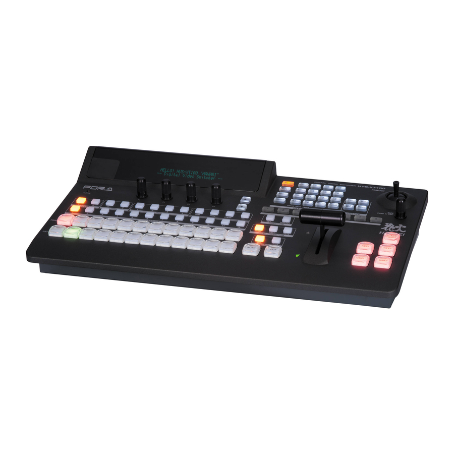
- Page 1 OPERATION MANUAL HVS-XT100/100OU HVS-XT110 Digital Video Switcher Edition...
- Page 2 Edition Revision History Edit. Rev. Date Description Section, Page 2013/08/30 1st edition...
- Page 3 Precautions Important Safety Warnings [Power] Operate unit only on the specified supply voltage. Caution Disconnect power cord by connector only. Do not pull on cable portion. Do not place or drop heavy or sharp-edged objects on power cord. A damaged cord can cause fire or electrical shock hazards.
- Page 4 [Circuitry Access] Do not remove covers, panels, casing, or access circuitry with power applied to the unit! Turn power off and disconnect power cord prior to removal. Internal servicing / adjustment of unit should only be performed by qualified personnel. Do not touch any parts / circuitry with a high heat factor.
- Page 5 HVS-XT100ED Editor Control Software HVS-XT110PSM Redundant Power Supply Unit Rack Mount Brackets 1 set EIA standard type HVS-XT100 Packing List HVS-XT100 (MU) Box ITEM REMARKS HVS-XT100 Switcher Main Unit (MU) AC cable 1 set Retaining clips included Quick Setup Guide...
-
Page 6: About This Manual
HVS-XT100OU Box ITEM REMARKS HVS-XT100OU Switcher Control Panel (OU) LAN cable For HVS-XT100 connection, 10m AC Adaptor 1 set AC cable and retaining clip included Options HVS-XT100PSO 1 set OU Redundant Power Supply Unit Rack Mount Brackets 1 set... -
Page 7: Table Of Contents
Table of Contents 1. Prior to Starting ......................... 15 1-1. About HVS-XT100 Series Switchers ................. 15 1-2. Features ..........................15 2. Panel Descriptions ........................16 2-1. HVS-XT100OU ........................16 2-2. HVS-XT100 ........................17 2-3. HVS-XT110 ........................19 2-4. Interfaces ........................... 21 2-4-1. - Page 8 5-8. Adjusting Video Signal Levels.................... 43 5-8-1. Proc Amp ........................43 5-8-2. Video Level Clip ......................43 5-9. Bus Matte ........................... 44 5-9-1. Setting the Matte Color ....................44 5-9-2. Setting the Gradient Matte ..................44 6. Video Outputs ..........................46 6-1.
- Page 9 8-8-4. Other Transition Settings ................... 71 8-9. Modifying Patterns ......................72 8-9-1. WIPE Type (No. 0-99) ....................72 8-9-2. DVE Type (No. 100-137).................... 74 8-10. KEY/DSK Transitions ...................... 76 8-10-1. Setting the KEY/DSK Transition Button Function ............ 76 8-10-2. USER Transitions ..................... 77 8-11.
- Page 10 11-1. Selecting a SUB EFFECT Channel and Source Signal ..........104 11-2. MONO COLOR ......................104 11-3. DEFOCUS ........................104 11-4. PAINT COLOR ....................... 105 11-5. FREEZE, STROBE, NEGA, MOSAIC ................105 12. Still and Clip Store ......................... 106 12-1. Managing Still Images ....................106 12-1-1.
- Page 11 15-1. Storing Events ....................... 135 15-2. Recalling Events ......................136 15-3. Protecting / Deleting Event Data ................... 137 15-4. Event Data ........................138 15-4-1. Data Not Saved in Events ..................138 15-4-2. Detailed Data Selection for Saving Events ............138 15-4-3.
- Page 12 18-7. Upgrading an Operational Version ................160 18-7-1. Upgrade Procedure....................160 18-7-2. Upgrading the Switcher ..................161 18-7-3. Loading Setting Data ....................161 19. Reboot and Initialize ......................162 19-1. Rebooting System ......................162 19-2. System Initialization ....................... 162 20. External Device Connection ....................163 20-1.
- Page 13 21-18-3. Setting Parameters to Default ................222 21-19. Backing Up Settings ....................222 22. Specifications and Dimensions .................... 223 22-1. Specifications ........................ 223 22-1-1. HVS-XT100 ......................223 22-1-2. HVS-XT100OU ....................... 224 22-1-3. HVS-XT110 ......................225 22-2. External Dimensions ..................... 227 22-2-1.
-
Page 15: Prior To Starting
1. Prior to Starting 1-1. About HVS-XT100 Series Switchers HVS-XT100 series HANABI switchers are powerful and compact 1M/E video switchers that are easy to use. They can be used in all types of locations, including at live and sporting events, in news studios, OB vans, editorial offices and presentation venues, making it the ideal tool for shaping the imaginative ideas of video creators. -
Page 16: Panel Descriptions
Indicates fan alarm status. Normally unlit, the indicator blinks red when an alarm occurs. In such case, power ALARM indicator off the system and consult your FOR-A supplier. (It also 18-6-1 blinks red when a power supply does not work in redundant configuration.) -
Page 17: Hvs-Xt100
18-6-1 occurs. In such case, power off the system and consult your FOR-A supplier. (It also blinks red when a power supply does not work in redundant configuration.) Used to connect a USB flash drive for image file import / 12-3 export or system setting backup. - Page 18 75-ohm terminated if not looped-through. LAN port , used for HVS-XT100OU connection (RJ-45) TO OU Use the supplied LAN cable with the HVS-XT100OU to connect the HVS-XT100 and HVS-XT100OU. Ethernet port used for image transport and web control 12-4-1 100BASE-TX/1000BASE-T (RJ-45)
-
Page 19: Hvs-Xt110
ALARM indicator 18-6-1 blinks red when an alarm occurs. In such case, power off the system and consult your FOR-A supplier. Used to select a bus, then to select a video in the BUS SELECT Block KEY/AUX bus (No 7). - Page 20 Rear Panel POW ER MODE SW DC1 2V IN RS-422 SDI I NPUT A UX GPI IN/TA LLY OUT GENLOCK SDI INPUT A UX REF IN REF OUT HDMI OUT Refer to Name Description sec. Power Switch Switch used to turn unit power ON / OFF. MODE SW For maintenance use.
-
Page 21: Interfaces
2-4. Interfaces 2-4-1. RS-422 Connector 1-2 Pin Assignment Table (9-pin D-sub ,female, with inch screws) Pin No. Signal Name In/Out Description Frame ground Receive data (-) Transmit data (+) Signal ground Not used Signal ground Receive data (+) Transmit data (-) Frame ground RS-422 ports are used for the following device connections. -
Page 22: Connection
3. Connection 3-1. HVS-XT100 / XT100OU 3-1-1. Basic Configuration REF signal PGM(AUX1) Video server, VTR, etc. Preview (AUX2) HD/SD SDI HD/SD SDI TSG (REF signal) REF IN REF OUT TO OU GENLOCK SDI INPUT HDMI OUT RS-422 GPI IN/TALLY OUT... -
Page 23: Installing The Power Cord Retaining Clamp
3-1-2. Installing the Power Cord Retaining Clamp AC cord clamp Installation 1) Wrap the retaining clamp around the AC cord (with the anchor of the ladder strap toward the unit). 2) Insert the anchor into the hole next to the AC IN socket. 3) Lightly fasten the clamp around the AC cord. -
Page 24: Optional Configuration
GENLOCK SDI INPUT HDMI OUT TO OU RS-422 GPI IN/TALLY OUT AC100-240V 50/60Hz IN AC100-240V 50/60Hz IN HVS-XT100 rear panel 75Ω-terminator To AC power source To AC power source GPI Controller GPI OUT Supplied LAN cable TALLY OUT POW ER... -
Page 25: Hvs-Xt110
3-2. HVS-XT110 3-2-1. Basic Configuration AC adaptor POW ER MODE SW DC1 2V IN RS-422 SDI I NPUT A UX GPI IN/TA LLY OUT GENLOCK SDI INPUT A UX REF IN REF OUT HDMI OUT TSG (reference) HD/SD SDI HD/SD SDI 75Ω... -
Page 26: Optional Configuration
3-2-2. Optional Configuration GPI Controller GPI OUT TALLY OUT adaptor adaptor POWER MOD E SW DC12V IN SDI INPUT AU X EDITOR RS-422 GPI IN/TALLY OUT GEN LOCK SDI INPUT AU X REF IN REF OUT HDMI OUT TSG (REF signal) 75Ω-terminator HD/SD SDI Multiview... -
Page 27: Power On
(1) Use the supplied LAN cable with the HVS-XT100OU to connect the TO OU connector on the HVS-XT100 rear panel and the TO MU connector on the HVS-XT100OU rear panel. (2) Use the supplied power cord to supply AC power to the HVS-XT100. Secure the power cord with the attached cord clamp. -
Page 28: System Signal Format Selection At Initial Use
3-4. System Signal Format Selection at Initial Use When first switching your unit on, select a signal format as shown below. (1) The MENU button in the SELECT/KEYPAD block at the right of the menu display should blink when powered ON. (2) Press MENU, then press SETUP. -
Page 29: Setting Date, Time And Time Zone At Initial Use
3-5. Setting Date, Time and Time Zone at Initial Use When first switching your unit on, set the date, time and time zone as shown below. (1) Press MENU in the SELECT/KEYPAD block, then press SETUP to display the SETUP top menu. -
Page 30: Menu Operation
4. Menu Operation 4-1. How to Access Menus 4-1-1. Menu Access Buttons Press MENU on the left side of the SELECT/KEYPAD block, then press the buttons on the keypad to access menus. DIGITAL VIDEO SWITCHER MENU button MENU ATTACH SETUP STILL MATT FILE... -
Page 31: Other Menu Access Buttons
4-1-2. Other Menu Access Buttons Asidefrom the menu buttons, the related menu pages can be displayed by pressing (buttons in C) or Double-pressing (quickly pressing twice) (buttons in A and B) specific buttons as shown in the tables below. HVS- DIGITAL VIDEO SWITCHER MENU ATTACH... -
Page 32: How To Set Values
4-2. How to Set Values 4-2-1. Displaying Parameters See section 4-1. "How to Access Menus" to display a desired menu. If a menu has multiple submenus such as the SETUP menu, navigate to submenus following the procedure below. Menu Navigation (Example for the SETUP menu) (1) Press MENU in the SELECT/KEYPAD block, then SETUP to display the SETUP menu. -
Page 33: Changing Settings Or Values Using F1 To F4
Page Navigation As shown in the example below, the [SETUP - INPUT - PROC AMP] submenu spreads across three pages. When first accessed, page 1 of 3 will be displayed. To go to page 2, simply press the page down button. Pressing the page up button returns you to page 1. Pressing the page up button when located on the first page brings you up one level in the menus. -
Page 34: Changing Settings Or Values Using The Numeric Keypad
Parameters with the sign ">" Parameters with ">" sign in front of them are executable by pushing the relevant menu control push-button. For example, pressing a menu control push-button initializes menus, stores/recalls still images, clips or setting files. See section 4-3. "How to Return Settings to Default." ... -
Page 35: Changing Settings Or Values Using The Joystick
4-2-4. Changing Settings or Values Using the Joystick Users can also use the joystick to set position, size and color settings to specific parameters. Menu pages controllable from the JOYSTICK block are shown in the table below. Controllable Parameters Parameter Menu Menu item... -
Page 36: How To Return Settings To Default
4-3. How to Return Settings to Default 4-3-1. Returning Parameters to Default Pressing and holding down Control Push-buttons Press and hold the control push-button (F1 - F4) below each parameter to return the resoectuve settings to their factory default. Briefly pressing the DEF button If you need to reset parameters that can be set by the joystick, display parameters and press the SIZE control (PUSH TO DEF). -
Page 37: Video Sources
5. Video Sources 5-1. How to Assign User Names to Sources Video inputs, Still1-2, StillKey1-2, Matte, Black and Color bar can be assigned user-specific names, to make them easier to identify for operators. User names can be given to input signals, internally generated black mattes and matte signals, and still pictures. -
Page 38: How To Assign Sources To Bus Buttons
5-2. How to Assign Sources to Bus Buttons Primary and optional video inputs, internally generated signals (black, mattes, etc.), and captured stills can be freely assigned to bus buttons using the procedure below. Signal-to-Button mappings are shared on the PGM/PST and KEY/AUX bus. (1) Press MENU, then SETUP to display the SETUP menu top page. -
Page 39: Resize Function
5-3. Resize Function A resize function allows users to input SD signals at the same frame-rate as that in HD mode, and enlarge them to use as HD images. The Resize function is available on 4 inputs: IN05 to IN08. (1) Display the [SETUP - INPUT] menu. -
Page 40: Input Still (Freezing Input Video)
5-4. INPUT STILL (Freezing Input Video) Video inputs (IN01 to IN08) can display frozen images (INPUT STILLs) by capturing video. Still images for INPUT STILLs can also be uploaded using the FILE menu. See section 12-4-3. "Sending / Receiving Still Images.") ... -
Page 41: Changing The Side Panel Image
5-5. Changing the Side Panel Image The side panel image of 4:3 video can be changed as shown in the procedure below. (1) Display the [SETUP - INPUT] menu. (2) Turn F1 to select SIGNAL. Press F1 or the page down button to display the [SETUP - INPUT - SIGNAL] menu. -
Page 42: Frame Synchronizer
5-7. Frame Synchronizer A video frame synchronizer is provided respectively for IN01 to IN08 and is used to synchronize asynchronous signals. Users can select whether to apply frame synchronization to input signals or not (for each signal) as shown in the procedure below. (1) Display the [SETUP - INPUT - SIGNAL] menu. -
Page 43: Adjusting Video Signal Levels
5-8. Adjusting Video Signal Levels 5-8-1. Proc Amp The switcher provides the following Proc Amp features. (1) Press MENU in the SELECT/KEYPAD block, then press SETUP to display the SETUP top menu. Turn F1 to select INPUT, then press F1 or the page down button to open the [SETUP - INPUT] menu. -
Page 44: Bus Matte
5-9. Bus Matte Matte signals can be assigned to any bus buttons for PGM, PST and KEY/AUX. (Default assignment: MAT1 to Button 12). Bus matte colors can be specified in the [MATT COLOR] menu. 5-9-1. Setting the Matte Color (1) Press MENU then press MATT in the SELECT/KEYPAD block to display the MATT menu. - Page 45 MATT2 :PATTERN : POS : SOFT : 4/4 GMAT : =H : =0 : =0 PATTERN setting Description COLOR1 Displays the matte color set at BUS MATT2 COLOR1. Displays a horizontal gradient from COLOR1 to COLOR2. Displays a vertical gradient from COLOR1 to COLOR2. Displays a diagonal gradient from COLOR1 to COLOR2.
-
Page 46: Video Outputs
6. Video Outputs REF IN REF OUT TO OU GENLOCK SDI INPUT HDMI OUT RS-422 GPI IN/TALLY OUT POW ER MODE SW AC100-240V 50/60Hz IN AC100-240V 50/60Hz IN DC1 2V IN RS-422 SDI I NPUT A UX GPI IN/TA LLY OUT GENLOCK SDI INPUT A UX... -
Page 47: Aux Video Switching With Effects
Available signal selections are as described below: Button Signal Refer to BLACK, IN01-08 (XT100) IN01-12 (XT110), Signals assignable to M/E and KEY/AUX bus buttons STILL1-2, STILLK1-2, CKFIL, CKKEY, MATT1-2, CLBAR, EFF1-2 Program video Preview video PREV (next video with or without KEY1-2 and DSK1-2) Clean video CLEAN (program video with or without KEY1-2 and DSK1-2) -
Page 48: Preview Set Up
6-2. Preview Set Up The switcher does not have a dedicated PREVIEW output. A preview bus output can be assigned to, however, an AUX output. Users can also add key images to PREVIEW. This can be done as explained below: 6-2-1. -
Page 49: Clean Set Up
6-3. Clean Set Up The switcher can output CLEAN video (background video of the program signal) via an auxiliary output. Users can also add KEY or DSK images to CLEAN. Follow the procedure below to assign the clean video to an AUX output. AUX3 is used in this example. Outputting the Clean Video from AUX 3 (1) Double-press AUX1 to display the [SETUP - OUTPUT- OUT XPT](1/3) menu. -
Page 50: Hdmi Output
6-5. HDMI Output Video output through the HDMI port can be selected from an M/E program, preview, clean or key out video, to AUX1-8 and MV. (1) Double-press AUX1 on the left side of the control panel to display the [SETUP - OUTPUT - OUT XPT] (1/3) menu. -
Page 51: Safety Area Markers
6-6. Safety Area Markers Various markers indicating the safety area, screen center and aspect ratio can be displayed on the desired output. (1) Open the [SETUP - OUTPUT] menu. (2) Turn F1 to select MARKER, then press F1 or the page down button to open the [SETUP - OUTPUT - MARKER] menu. -
Page 52: Ancillary Data
6-7. Ancillary Data Ancillary data does not pass through all outputs as the factory default setting. The switcher can be set to pass or blank the ancillary data in the AUX outputs using the menu. The switcher also allows users to pass or substitute ancillary data in the Program (Clean) and Preview video. -
Page 53: Aux Link
6-8. AUX LINK In the AUX-LINK function, the auxiliary outputs are grouped, and the master and slave outputs are set to allow all slave output signals to be switched simultaneously by simply selecting the master output signal. A group consists of one master output and up to three slave outputs. Seven auxiliary output groups can be set. -
Page 54: Enabling Aux Link
(2) Turn F1 to select an AUX LINK group to be set in the LINK GROUP menu (up to 20 groups). (3) Turn F2 to select a signal to be set for MASTER (4) To set the SLAVE output signals (up to three) that link to the MASTER output signal, press F3 and then turn F3 to select a signal for Slave 1. -
Page 55: Bus Operation
7. Bus Operation Video signals that are input to the switcher are assigned to the bus buttons on the control panel for usage. The assigned signals are shared by the M/E(PGM/PST) and KEY/AUX bus sections. As factory default settings, video inputs, Stills and Mattes are assigned to the bus buttons. The video source assignments are freely changeable. -
Page 56: Selecting Video Sources For Aux1 To Aux4
7-1-2. Selecting Video Sources for AUX1 to AUX4 (1) Press the desired AUX button. (2) Press a desired button on the KEY/AUX bus. Ex.1) To Select IN1 for AUX1 Press AUX1. Then press 1 (IN01) on the KEY/AUX. PREV CL EAN KEYER KEY/AUX Ex. -
Page 57: Button Switching Mode In The M/E Bus
7-2. Button Switching Mode in the M/E Bus Users can change the button switching mode for the M/E bus from P/P (PGM/PST) to A/B. In P/P mode (default), the source selections in the PGM and PST buses are switched when transitions occur and users can always select the next background signal from the PST bus (the bottom row). -
Page 58: Using The Shift Function
7-3-2. Using the SHIFT Function Once the SHIFT function has been assigned to a bus button, an additional 11 buttons are available for signal selection. This chapter explains how to select signals with the SHIFT button. Assume that video sources and the shift function are assigned to bus buttons as shown in the table below: Bus button 1 IN01 Bus button 1 (shifted) -
Page 59: Transitions
8. Transitions Available Transitions on the M/E (PGM/PST) bus BLACK transition: MIX Background: CUT, MIX and Pattern transitions KEY1 and 2: CUT, MIX and Pattern transitions SLIDE (4-direction), SCALER and WIPE (4-direction) transitions DSK1 and 2: CUT and MIX transitions SLIDE (4-direction), SCALER and WIPE (4-direction) transitions -Transitions setup by next transition bus selection... -
Page 60: Transition Block Description
8-1. Transition Block Description NOR/REV DIRECTION BLACK TRANS BKGD KEY1 KEY2 NEXT TRANSITION KEY1 KEY2 WIPE TRANSITION TYPE AUTO DSK1 DSK2 Description Pattern transition direction setting buttons Next transition bus selection buttons Transition type selection buttons for BKGD, KEY1 and KEY2 AUTO transition button for BKGD and KEY1 and KEY2 CUT transition button for BKGD and KEY1 and KEY2 Fader lever for performing BKGD, KEY1 and KEY2 transitions... -
Page 61: Background Transitions
8-3. Background Transitions This chapter explains how to perform background transitions. CUT Transition (1) Select a video source in the PST bus block. (2) Press the BKGD button in the NEXT TRANSITION block. (3) Press CUT to perform the background CUT transition. NOR/REV DIRECTION BLACK... - Page 62 See section 8-8. "Pattern (WIPE) Transitions" for the WIPE transition details. See section 8-11-2. "Transition Rate" for the transition rate. See section 8-11-3. "Transition Limit" for the transition limit. To Check Next Video: To check the Preview video, assign the Preview video to an AUX bus to display the image. ...
-
Page 63: Key Transitions
8-4. KEY Transitions Key images are displayed on the M/E (background) output screen. This chapter explains how to perform key transitions using KEY1 as an example. 1. Perform key setup for KEY1. See section 9. "KEY/DSK." 2. Perform a desired transition referring to the below procedures. CUT Transition (1) Press KEY1 in the NEXT TRANSITION block. - Page 64 (4) Press AUTO or KEY1, or move the fader lever to perform the pattern transition. NOR/REV DIRECTION BLACK TRANS BKGD KEY1 KEY2 NEXT TRANSITION KEY1 KEY2 WIPE TRANSITION TYPE AUTO DSK1 DSK2 The KEY1 transition button behaves the same as the AUTO button when selecting KEY1 for the next transition.
-
Page 65: Dsk Transitions
8-5. DSK Transitions DSK images are displayed on the M/E (background) or an AUX output screen. This chapter explains how to perform DSK transitions using DSK1 as an example. See section 8-5-1. "Where DSK Images Appear." 1. Perform key setup for the DSK1. ... -
Page 66: Simultaneous Bkgd And Key Transitions
8-6. Simultaneous BKGD and Key Transitions Background and key transitions can be performed simultaneously. This chapter explains how to perform simultaneous BKGD, KEY1 and KEY2 transitions as an example. (1) Set transition types for the background, KEY1 and KEY2 to MIX or WIPE, respectively. Select a pattern using the menu if set to WIPE. -
Page 67: Pattern (Wipe/Dve) Transitions
8-8. Pattern (WIPE/DVE) Transitions Pattern transitions are available for Background, KEY1 and KEY2. See section 8-3. "Background Transitions." See section 8-4. "KEY Transitions." This chapter explains details on the pattern selection method and transition direction. 8-8-1. Selecting a Pattern (1) Press WIPE in the transition block to display the [TRANS] (1/6) menu. -
Page 68: Use Limitations For Pattern Transitions
8-8-2. Use Limitations for Pattern Transitions When using a WIPE type pattern (0-99): Pattern transitions cannot be simultaneously performed both on KEY1 and KEY2. If both KEY1 and KEY2 pattern transitions are performed, one transition is automatically changed to MIX. ... -
Page 69: Direct Pattern Function
8-8-3. Direct Pattern Function The Direct Pattern Selection feature allows users to select a pattern easily and quickly. The feature uses the number buttons on the keypad (0-9), to which WIPE patterns previously registered can be recalled at the touch of a button. Up to 20 patterns can be registered as direct patterns under two pages (PAGE 0 and PAGE 1). - Page 70 To Select Pattern 20: (1) Press DIRECT PATT to change the keypad to DIRECT PATTERN mode. MENU ATTACH (2) Press 1 on the Keypad. Pattern 20 will be SETUP STILL MATT FILE selected and the transition type is automatically DIRECT DETACH switched to WIPE.
-
Page 71: Other Transition Settings
8-8-4. Other Transition Settings Transition Direction Two direction buttons (NOR/REV, REVERSE) are used to set the pattern transition direction as shown in the table below. Transition direction NOR/REV button REV button Always Normal Unlit Unlit Always Reverse Unlit Normal at Normal/Reverse operation Unlit Reverse at Normal/Reverse operation Transition Rate... -
Page 72: Modifying Patterns
8-9. Modifying Patterns Preset patterns can be modified using the WIPE menu. Two pattern types are available: WIPE and DVE. Each type has its own menu pages. Pattern No. Type of Group Available modification settings 0 to 99 WIPE 2D border, multi, 2D position, 2D size, etc. 100 to 137 DVE (2D DVE) 2D border, 2D position, 2D size, crop, etc. - Page 73 Modify Pattern 20 This modification example adds a border to the background transitions using Pattern 20. (1) Select a desired signal on the PST bus. (2) Press BKGD in the NEXT TRANSITION block. (3) Press WIPE. The [TRANS] (1/6) menu is displayed. (4) Press F4 to enter 20 in the keypad, then press ENTER.
-
Page 74: Dve Type (No. 100-137)
To Register the Modified Pattern to a Direct Pattern: Refer to section 8-8-3. "Direct Pattern Function" to save a modified pattern to a direct pattern. To Reset the Modified Pattern: (1) Press WIPE in the transition block to display the [TRANS] (1/6) menu. The letter "M" (Modified) will be displayed in front of 20. - Page 75 Modify Pattern 117 This modification example also adds a border effect to KEY1 transitions using Pattern 117. However Pattern 117 has different border settings than Pattern 20, and can be used for both inside and outside border effects. (1) Set up KEY1. ...
-
Page 76: Key/Dsk Transitions
8-10. KEY/DSK Transitions KEY1 and KEY2 transitions can be performed not only through the BKGD AUTO button and fader lever, but also through key transition buttons (KEY1 and KEY2 in the transition section) and user buttons, to which key transition functions are assigned. DSK1 and DSK2 transitions can be performed through DSK transition buttons (DSK1 and DSK2 in the transition section) and user buttons, to which DSK transition functions are assigned. -
Page 77: User Transitions
The buttons are set to AUTO as factory default. The transition buttons function as shown in the table below. Parameter Setting Description KEY1 Always performs AUTO transitions regardless of how long the button is pressed. KEY2 AUTO (default) DSK1 Always performs MIX transitions regardless of how long the button is pressed. -
Page 78: Transition Settings
8-11. Transition Settings 8-11-1. TRANS Menu To display the [TRANS] menu, press MENU, then TRANS RATE in the SELECT/KEYPAD block. The [TRANS] menu consists of six pages for each bus. Use the page down or up button to move between pages. Parameter Description Refer to sec. -
Page 79: Transition Limit
8-11-3. Transition Limit The Transition Limit setting determines how far your transition can proceed. When performing transitions (mix or other) there may be times when you want the transition to the next signal to only complete to a certain degree instead of fully switching from one picture to another. -
Page 80: Key/Dsk
9. KEY/DSK The key feature enables you to superimpose titles and images onto background signals. With the switcher, four key channels are provided: KEY1-2 and DSK1-2. Three key types are available in all keyers: Luminance Key, Full Key and Bus Key. Key Invert, Mask and 2D DVE effects can also be added to keys. -
Page 81: Luminance Key
Bus Key Bus Key, also called External Key, uses different images for Key Source and Key Insert. The background signal is cut out using Key Source and Key Insert fills in the cut-out part of the signal. Bus key INVERT BOX(OR) mask... -
Page 82: Full Key
9-2. Full Key (1) Follow Step (1) to (4) in "Luminance Key" above. (2) The [KEY1 - INS/SRC] menu is displayed. Turn F1 to set TYPE to FULL. The insert signal can also be selected at INSERT. KEY1 : TYPE :INSERT :SOURCE :INVERT : 1/4 INS/SRC : =FULL... -
Page 83: Key Link
9-3-1. Key Link A Key Source signal can be selected concurrently when a Key Insert signal is selected if KEY LINK is on. The INSERT/SOURCE signal pairs for Bus keys are automatically set once they are selected for a key. To change signal assignment, select the INSERT/SOURCE signal pair again for the key or another key. -
Page 84: Adjusting The Key Signal
9-4. Adjusting the Key Signal Clip and Gain allows users to adjust the key signal and its composition over the background. KEY transparency can also be adjusted. (1) Double-press KEY1 above the KEY/AUX bus to display the [KEY1 SETUP] menu. (2) Turn F1 to select INS/SRC, and press F1 or the page down button. -
Page 85: Mask And Invert
9-6. Mask and Invert Mask and Invert can be used for all keys. Preset masks are available only for KEY1 and KEY2. Bus key INVERT BOX(OR) mask 9-6-1. Inverting Key and Background Setting Invert to ON inverts the key image and the background image. Set INVERT in the [KEY1 - INS/SRC] menu to ON. - Page 86 Signal Mask Video inputs can be used for mask signals instead of Box. Inputs used for masks must be assigned to AUX1 to AUX8. Combined video signals such as program or multi-view cannot be used. (1) Open [KEY1 - MASK] menu PAGE 1. (See the previous page.) (2) Turn F3 to select a mask signal.
-
Page 87: Key Edge
9-7. Key Edge The EDGE function allows users to add border type edges on KEY1 and KEY2. Two types of edges are available: Normal and Outline. The width, transparency, and color can be set for the edges. Shadow effects can also be added by changing the position of edges. This chapter shows how to add a key edge using KEY1 as an example. -
Page 88: Dve Effects On Key/Dsk
9-8. DVE Effects on KEY/DSK Dedicated 2D-DVE(2.5D) effects are available for each key in the standard configuration. 2D-DVE is available just by setting 2D DVE to ON in each key menu. As an example, this section explains how to add a 2D-DVE effect on KEY1. 9-8-1. -
Page 89: Changing Position And Size
9-8-2. Changing Position and Size The position and size of key images can be changed using the menu or joystick as follows: Using the Joystick: (1) Press the KEY1 menu button (with MENU lit) while holding down POS in the joystick block. -
Page 90: Changing The Aspect Ratio
9-8-3. Changing the Aspect Ratio (1) Go to the [KEY1 - POS/SIZE] menu PAGE 2. (2) Press MENU in the joystick block. (3) Change the KEY1 ASPECT values by moving the joystick up, down, left and right. KEY1 ASPECT :FADE LV: : 2/5 ASPECT :X=1000... -
Page 91: Rotation:x=0
9-8-5. Rotation In addition to positional and size changes, users can add a rotation effect to key images. Specifying the Rotation Angle (Number of Rotation) Using the Joystick (1) Press ROT for 2D DVE in the joystick block. (2) Move the joystick (X/Y-axes) and SIZE control (Z-axis) to change the rotation angles. Using the Menu (1) Go to PAGE 3 of the [KEY1 - POS/SIZE] menu. - Page 92 Setting Example (1) Set the key position and size on PAGE 1 of the [KEY1 - POS/SIZE] menu. Note that the position is two-dimensional and its origin is placed on (0, 0), which coincides with the center of the screen. The position values represent the distance between the origin and the center of the KEY1 images.
-
Page 93: Crop
[Example 2] Y-axis Rotation POSITION (-200,-200) SIZE 500 CENTER POSITION (150,-200,-400) LOCAL ROTATION (0,0,100) Center of rotation Screen surface Point of view [Example 3] Z-axis Rotation POSITION (-200,-200) SIZE 500 CENTER POSITION (150,-200,-400) ROTATION (0,0,100) Center of rotation Screen surface Point of view 9-8-6. -
Page 94: Borders
9-8-7. BORDERS Borders can be added to key images. Inside borders and outside borders can be adjusted independently. (1) Go to the [KEY1 - BORDER] menu. (2) To use the inside border, set the width on the INSIDE X and Y. To use the outside border, set the width on the OUTSIDE X and Y. -
Page 95: Chromakey
10. Chromakey The chromakey method of key signal creation, which uses a chroma component instead of a luminance component, is mostly used to composite moving subjects such as a person inside a virtual background environment. For example, to place a person over a virtual background, first film the person standing in front of a background such as a blue screen. - Page 96 Creating a Chromakey (1) Press MENU, then CK in the SELECT/KEYPAD block to display the [CHR KEY SETUP] menu. (2) Turn F1 to select AUTO CK, then press F1 to display the [CHR KEY - AUTO CK] menu. (3) Turn F4 to select a signal used for chromakey under SIGNAL. (4) Turn F3 to change SELECT to ON to activate the Auto Chroma key.
-
Page 97: Adjusting Chromakey
10-2. Adjusting Chromakey If the desired result is not achieved using the automatic chromakey generation procedure, fine adjustments can be made as follows: Use EDGE SHRINK and EDGE REPLACE to smooth Adjust key levels to chroma key edges. See section 10-2-3. make the background clear. -
Page 98: Adjusting The Foreground Image (Chromakey Color)
(3) Adjusting the KEY Cut Signal (Foreground) Remove unwanted noise from foreground areas (figures or objects) following the procedure below. Remove noises while monitoring the key cut image. (a) Use the parameters in the [CHR KEY - ADJUST] menu PAGE 2 and 3 to decrease the level one by one and check the chromakey image. -
Page 99: Adjusting Edges
WHITE Effective for reflections on white hair, skin or clothes. BLACK Effective for reflections on black hair, skin or clothes. Effective for reflections on reddish hair, skin or clothes. BLUE Effective for strong blue reflections. GREEN Effective for strong green reflections. CHR KEY :SELECT :SUPPRES:SOLDNES: WHITE : 4/5 SUPPRES : =ON : =0... -
Page 100: Chromakey Menu
10-3. Chromakey Menu To display the Chromakey menu, press MENU, then CK in the SELECT/KEYPAD block. To create and adjust a Chromakey, go to each submenu and set or adjust parameters. 10-3-1. [CHR KEY - ADJUST] Menu CHR KEY :>AUTO CK >ADJUST >MATT >FORGRND... -
Page 101: Chr Key - Matt] Menu
WHITE -100 to 100 Finely adjusts SUPPRESSION. BLACK -100 to 100 -100 to 100 GREEN -100 to 100 BLUE -100 to 100 10-3-2. [CHR KEY - MATT] Menu CHR KEY :>AUTO CK >ADJUST >MATT >FORGRND SETUP :>INIT CHR KEY : EDGE SHRINK : 1/3 CK ADJT :T=OFF... -
Page 102: Chr Key - Forgnd] Menu
10-3-3. [CHR KEY - FORGND] Menu CHR KEY :>AUTO CK >ADJUST >MATT >FORGRND SETUP :>INIT CHR KEY :RSV FLT:L&D EMP: : 1/2 FOREGND : =0 : =0 CHR KEY : EDGE REPLACE : 2/2 FOREGND :T=OFF B=OFF L=OFF R=OFF Parameter Default Setting range Description... -
Page 103: Assigning The Chromakey To Another Key Or Dsk
10-4. Assigning the Chromakey to Another KEY or DSK The following example shows how to use the Chromakey set up for KEY1 (background video: PST) in DSK1. (1) Open the [SETUP - FUNCTION - M/E KEY] menu. Turn F3 to change the DSK1 display from PGM to AUX3 (Do not select PGM for the AUX3 video.). -
Page 104: Sub Effect Channel
11. SUB EFFECT Channel The SUB EFFECT menu allows users to add MONO COLOR, DEFOCUS, and PAINT COLOR effects to input video or still images.Two SUB EFFECT channels can be used in the switcher. Video that is output from these channels are called SBEF1 and SBEF2 and can be directly output to other devices and used as key fill, key source and background signals. -
Page 105: Paint Color
11-4. PAINT COLOR The Paint color effect allows users to add an effect, which makes the image look like a painting. Increasing the value decreases the degree of gradation, for the image to start resembling a painting. (1) Display [SUB EFFECT1] PAGE 2. (2) Turn F3 to set the luminance level at item Y (LUMINANCE). -
Page 106: Still And Clip Store
12. Still and Clip Store 12-1. Managing Still Images The switcher can capture and memorize up to 2 Video and Key Still pictures from the switcher output video. Once stills are captured and stored, they can be directly output to other devices and used as key fill, key source and background signals. -
Page 107: Backing-Up Stills
12-1-3. Backing-up Stills To Save Still Images: (1) Press MENU, then STILL in the SELECT/KEYPAD block to display the menu (2) Press page down to go to PAGE 2. (3) Turn F1 to select STIL1 or STIL2 to be backed up. (4) Turn F2 to select SAVE>. -
Page 108: Managing Clips
12-2. Managing Clips Clip stores allow you to record and play output video. Up to 2 video and key pair signals can also be recorded simultaneously. Clip data can be stored in 2 still memory buffers with still data. In addition, sequential image files can be transferred from a computer and saved in the memory as a video clip. - Page 109 Recording Video and Key Signals Simultaneously Assume a video signal is assigned to AUX3 and its key signal to AUX4. If you need to record an input signal such as IN01, assign the signal to an AUX bus before recording.
-
Page 110: Playing Clips
12-2-2. Playing Clips Ex. 1: Playing the Recorded Clip on the AUX1 bus This example shows how to play the recorded clip in the previous section on the background through STILL1. Assume that STILL 1 is assigned to bus button 1 . (1) Open PAGE 1 in the [STILL] menu. -
Page 111: Clearing Clip Data
(7) Display KEY1 on the PGM image by pressing KEY1 to the right side of the fader lever. All IN/OUT effects for KEY 1 are available. See section 8-10. "KEY/DSK IN/OUT Effects." (8) Go to PAGE 3 in the [STILL] menu. Turn F1 to select STL2 (STILL2) and set the IN and OUT points. -
Page 112: Backing-Up Still And Clip Data Using Usb Flash Drive
12-3. Backing-up Still and Clip Data using USB Flash Drive All still and clip backup data can be automatically saved to a USB flash drive. Once the Automatic Backup is enabled, a backup is performed every time the user stores an image or clip to a buffer, STILL1-2, INPUT_STILL1-12 or CLIP1-2. -
Page 113: Setting Automatic Backup To On
Backup Folders in your USB Flash Drive The following folders are automatically created in a USB flash drive when backing up through the USB flash drive. / (Root) CLIP1 Used for uploading backup movie clips (sequential files) to | STILL1-2. -
Page 114: Deleting Backup Data
12-3-4. Deleting Backup Data (1) Insert the USB memory stick, in which the backup data is stored, into the USB port. (2) Go to [STILL] menu PAGE 3. (3) Turn F1 to select a still, input still, clip or all data to be deleted. (4) Turn F2 to select DELETE. -
Page 115: Transferring Image Files
12-4. Transferring Image Files The switcher can send and receive image data used for stills and video clips by connecting a PC through LAN (Ethernet). The FTP protocol is used to transfer files between the switcher and the computer. The switcher incorporates an FTP server. 12-4-1. -
Page 116: Image Files
PC Requirements and Network Settings An Ethernet port (100BASE-TX/1000BASE-T) and FTP client function are required for the personal computer. Any type of computer or OS can be used. In this section a Windows XP or 7-installed PC is used as an example. Network Setting IP Address 192. - Page 117 Still Directory Structure in the Main Unit (Root) ----- (still1)--------- still.jpg Still images for STILL1 are stored in JPEG, TGA and still.tga BMP format. To send image files to STILL1, specify still.bmp this directory. (still2)--------- still.jpg Still images for STILL2 are stored in JPEG, TGA and still.tga BMP format.
-
Page 118: Sending / Receiving Still Images
12-4-3. Sending / Receiving Still Images (1) Connect the Ethernet ports on the PC and Main Unit directly using a LAN cross-over cable (UTP). Switcher Computer IP address: LAN cross-over cable (UTP) 192.168.0.10 (default) IP address: 192.168.0.100 (2) Click on the Start button, then on the Control Panel option. (3) Enable the passive mode as shown below. -
Page 119: Sending Images To Clip Memory
12-4-4. Sending Images to Clip Memory Preparation (1) Prepare sequential image files in the following name format. File name: [STILLXXX.yyy] XXX: Indicates Serial numbers. 000 to 226 (1080/59.94i, 29.97PsF) 000 to 219 (1080/50i, 25PsF, 24PsF, 23.98PsF) 000 to 498 (720/59.94p, 50p) 000 to 998 (NTSC, PAL) -
Page 120: Cg Wipe
12-5. CG WIPE CG WIPE allows you to create a sequence in which a CG video, which is displayed using a KEY, moves in accordance with the motion of a WIPE or DVE pattern. CG WIPE patterns are usually modified according to sequences. To play CG wipes, the CG WIPE clip must be saved to a still buffer and a key channel is required for CG display. -
Page 121: Cg Wipe Operation Example 1
12-5-1. CG WIPE Operation Example 1 Ex. 1: CG WIPE using STILL1 and KEY1 In this example, it is assumed that a CG (V + K) is stored in STILL1. Set IN/OUT points, and delay and transition rates, if necessary. Assign STILL1 and STILL KEY to KEY1 signals, display KEY1 on the screen and play the CG through KEY1. -
Page 122: Saving Cg Wipe Settings
12-5-2. Saving CG WIPE Settings CG WIPE settings can be saved as WIPE pattern modification settings in Direct Pattern and in the event memory. See section 8-8-3. "Direct Pattern Function" See section 15. "Event Memory." 12-5-3. CG WIPE Menu Quick Reference (1) Display the [WIPE] menu by pressing MENU then WIPE in the SELECT/KEYPAD block. -
Page 123: Multiviewer
The multiviewer function allows users to monitor multiple images such as video sources input to the switcher and internally generated or combined images on the same screen. The HVS-XT100 series switcher provides one channel output in 2/4/5/7/9/10/11/16 split screen formats. In addition, up to 8 layout patterns including video mapping can be saved and recalled.Video titles and on-air tally... -
Page 124: Video Signal Mapping
The available layout formats are 2, 4, 5, 7, 9, 10, 11 and 16-way as shown below. 13-3. Video Signal Mapping Let's assign PGM, PVW, IN01 and IN02 video signals to the set quad screen as shown below. IN01 IN02 image image image... -
Page 125: Setting Up Each Split Area
13-4. Setting Up Each Split Area 13-4-1. Titles (1) Double-press the MV button in the KEY/AUX bus block to display the menu. (2) Go to PAGE2 OUTPUT :SCREEN :SIGNAL : CHARA : : 2/7 : =PVW : =SHORT: Turn F1 to select a screen number (split area). Turn F3 to select the type of title display. -
Page 126: Audio Level Meter
Changing Output Signal Names Open the [SETUP - OUTPUT - RENAME] menu and change names, as necessary. OUTPUT :SELECT :SHORT : LONG NAME(MV) : 1/1 RENAME : =PGM : =PGM : = PROGRAM SELECT SHORT (Default) LONG NAME (Default) Description PROGRAM M/E program outputs... -
Page 127: Frame Border
13-4-4. Frame Border Frame borders can also be applied to the split-screen to emphasize channel areas. (1) Open PAGE 5 in the [SETUP - OUTPUT - MV] menu. (2) Turn F4 to select a border color among eight standard colors. Press F4 to apply the selected color. -
Page 128: Saving / Loading Screen Layouts
13-5. Saving / Loading Screen Layouts Up to eight screen layout patterns can be saved to / loaded from the [SETUP - OUTPUT - MV] menu. 13-5-1. Saving a Screen Layout (1) Open PAGE 1 in the [SETUP - OUTPUT - MV] menu. (2) Turn F3 to select the memory number. -
Page 129: User Buttons
14. USER Buttons User buttons can be assigned to specific menu pages and used as shortcuts or specific functions buttons. Follow the procedure below to assign the desired menu page or function to buttons. USER 1-8 butttons HVS- DIGITAL VIDEO SWITC HER MENU ATTACH POSITION... - Page 130 Assignable Menu Page Setting (Accessed menu page) FILE TOP MENU DSK1-2 MATT MENU FILE LOAD MENU DSK1-2 GAIN/CLIP MENU FILE SAVE MENU DSK1-2 POS/SIZE MENU SYSTEM-FORMAT MENU DSK1-2 CROP MENU EDITOR MENU DSK1-2 BORDER MENU MV MENU AUTO CK MENU STATUS MENU STILL MENU KEY1-2 EDGE MENU...
- Page 131 When KEYER is selected for TYPE: Setting Function Button Indication KEY [DSK] 1-2 2D DVE ENABLE Sets 2D DVE On/Off. KEY [DSK] 1-2 BOX MASK AND ENABLE Sets AND type BOX MASK On/Off. KEY [DSK] 1-2 BOX MASK OR ENABLE Sets OR type BOX MASK On/Off.
- Page 132 When STILL is selected for TYPE: Setting Function Button Indication STILL1-2 STORE Performs still captures. Always lit orange Captures and saves or clears a still image for Image stored: Lit orange, INPUT1-8 STILL STORE INPUT STILL 1 to 8. Image not stored: Lit white Captures and saves or clears a still image for INPUT STILLs using KEY/AUX bus INPUT STILL STORE...
-
Page 133: Triggering User Buttons
14-2. Triggering User Buttons User buttons can be triggered (activated) by state changes (ON/OFF) in tally or GPI function items. This chapter shows how to set settings for these examples in the USER BUTTON menu. Three typical examples are shown below: Ex. - Page 134 <Ex. 3> To execute the Ex. 3 procedure using USER Button 3, set the menu as shown below. (1) Set items on PAGE 1 of the [USER BUTTON] menu as shown below. USER :SELECT : TYPE : FUNC(F3) : 1/2 BUTTON : =OU-3 =VTR...
-
Page 135: Event Memory
15. Event Memory The switcher can save control panel setup states as data for recall when needed. This function is called Event Memory. This Event Memory function enables quick recall of previously saved setting states. The event memory data can accurately reproduce panel settings and selections including pattern modification and key setup, because the event memory data holds all panel information. -
Page 136: Recalling Events
15-2. Recalling Events Let's load EVENT 12 (PAGE1, Number Button 2) saved in the previous page to the control panel. (1) Press EVENT in the SELECT/KEYPAD block. The [EVENT MEMORY] menu is displayed and the keypad switches to EVENT mode. (2) Turn F1 to select 1 (PAGE 1) in the [EVENT MEMORY] menu. -
Page 137: Protecting / Deleting Event Data
15-3. Protecting / Deleting Event Data This chapter sets write protection on EVENT 12 as an example. The data can be deleted from EVENT 12 in the same menu page. (1) Press EVENT in the SELECT/KEYPAD block to display the [EVENT MEMORY] menu. (2) Select 1 (PAGE 1) in the [EVENT MEMORY] menu. -
Page 138: Event Data
15-4. Event Data 15-4-1. Data Not Saved in Events All SETUP menu settings All FILE menu settings STILL images ADV CTRL settings in the TRANS menu (See section 8-10-1.) 15-4-2. Detailed Data Selection for Saving Events When STORE is pressed while storing events, the [EVENT STORE] menu is displayed and data to be saved to the event can be selected in the menu as shown below. -
Page 139: Setting The User Default Menu When Storing An Event
15-4-3. Setting the User Default Menu when Storing an Event The [EVENT STORE] menu appears as shown below in the factory default setting when storing events. EVENT :SELECT : XPT : DATA : RATE : 1/2 STORE : =ALL : =ON : =ON : =0 :P.00... -
Page 140: Transitions Using Event Recall
15-5. Transitions Using Event Recall The RATE parameter in the EVENT menu allows users to set the duration time (transition rate) for loading events. With this duration time, two images before and after recalling events that appear on program screens are automatically interpolated to create a smooth transition. The RATE setting is made while storing events. -
Page 141: Loading An Event At Start-Up
15-6. Loading an Event at Start-up The settings made for the background and key buses on the control panel are cleared when powering off the switcher. You can, however, recall the desired panel setup whenever the switcher starts by setting in the [SETUP - SYSTEM - INIT] menu as shown in the procedure below. -
Page 142: Macros
16. Macros The Macro function allows users to perform a sequence of recorded operations with the single push of a button. The keypad is used to record and execute macros. The macro memory data can be backed up and then restored from USB flash drives. ... -
Page 143: Executing Macros
16-2. Executing Macros Let's execute Macro 12 (PAGE1, Number Button 2) saved in the previous page on the control panel. MENU ATTACH (1) Press MACRO in the SELECT/KEYPAD block. SETUP STILL MATT FILE The [MACRO MEMORY] menu is displayed and DIRECT DETACH PATT... -
Page 144: Operation Example 2
16-2-2. Operation Example 2 Recording Actions as Macro 10 Let's perform the following actions and record them as Macro 10 (PAGE 1, Number Button 0). -Select Button 11 on the PST bus. -Set the background transition type to MIX. MENU ATTACH -Perform background transitions using the fader lever. -
Page 145: Macro Memory Operation
16-3. Macro Memory Operation 16-3-1. Overwrite Protection (1) Press MACRO in the SELECT/KEYPAD block to display the [MACRO MEMORY] menu. (2) Turn F1 to select a memory page. Set DIRECT to OFF, if it is ON. MACRO : PAGE :DIRECT :PAGECLR: MEMORY : =OFF : >CRNT :... -
Page 146: Deleting Macros
16-3-3. Deleting Macros To Delete Data for a Macro (1) Press MACRO in the SELECT/KEYPAD block to display the [MACRO MEMORY] menu. (2) Turn F1 to select a memory page. Set DIRECT to OFF, if it is ON. MACRO : PAGE :DIRECT :PAGECLR: : 1/3... -
Page 147: Macro Execution Buttons
16-4. Macro Execution Buttons 16-4-1. Changing KEY/AUX Bus Buttons to Macro EXE Buttons Stored macros can be executed using the KEY/AUX bus buttons and a USER button, to which the MACRO BUS SELECT function is applied. Once the USER button, to which MACRO BUS SELECT is assigned, is pressed to turn on. The KEY/AUX bus buttons 1 to 12 change to the Macro EXE Buttons. -
Page 148: Macro Attach And Macro Detach
16-4-2. Macro Attach and Macro Detach Any button on the control panel can be used as a macro execution button. To do so, assign a macro to a button (Macro Attach). Once a macro is attached to a button, the macro is executed whenever the button is pressed. -
Page 149: File Operation
USB flash drive. The remaining storage space on the USB memory device is displayed at the bottom right-hand side in the FILE menu. HVS- DIGITAL VIDEO SWITC HER DIG ITAL VIDE O SW ITCH ER HVS-XT100 MENU ATTACH POSITION SETUP STILL... -
Page 150: Saving Data To Usb Flash Drives
17-3. Saving Data to USB Flash Drives This section explains how to save panel settings to USB memory using a "data.all" file as an example. (1) Insert a USB flash drive into the USB port. (2) Press MENU in the SELECT/KEYPAD block, then press FILE to open the FILE top menu. (3) Turn F1 to select SAVE, and then press F1 or the page down button to open the [FILE - SAVE] menu. -
Page 151: Loading Data From Usb Flash Drives
17-4. Loading Data from USB Flash Drives 17-4-1. Loading Setting Data This section explains how to load setting data to the USB memory by using a "data.all" file as an example. (1) Insert a USB flash drive into the USB port. (2) Press MENU in the SELECT/KEYPAD block, then press FILE to open the FILE top menu. -
Page 152: Moving Between Usb Flash Drive Directories
Image files can be uploaded to the following memory buffers in the switcher: Description Upload destination (LOAD setting using F2) STILL1 to STILL2 Uploads an image file to a still memory buffer. STILL1C to STILL2C Uploads an image file to a still memory buffer in a centered format. -
Page 153: Deleting Files From Usb Flash Drives
17-6. Deleting Files from USB Flash Drives The user can delete files from USB flash drives using the FILE menu operation. (1) Open the [FILE - LOAD] menu. If you are in the [FILE - SAVE] menu, press the page up button to go to the FILE top menu and move to the [FILE - LOAD] menu. -
Page 154: System Setup Settings
18. System Setup Settings 18-1. Selecting System Signal Format (1) Press MENU in the SELECT/KEYPAD block, then press SETUP to display the SETUP top menu. (2) Turn F1 to select SYSTEM, then press F1 or the page down button to open the [SETUP - SYSTEM] menu. -
Page 155: Selecting A Reference Signal
18-3. Selecting a Reference Signal The switcher provides a reference input, its loop-through and output connectors in the GENLOCK section on the rear panel. 18-3-1. To Set Reference Input (1) Press MENU in the SELECT/KEYPAD block, then press SETUP to display the SETUP top menu. -
Page 156: Setting Time Using Sntp (Time) Server
IMPORTANT The date and time information are used for the multiviewer clock and when backing up image or setting files. Note that date and time information may be lost if the switcher is powered OFF for more than 100 hours (or less if it is not fully charged). In such case, reset the date and time. -
Page 157: Buzzer, Brightness And Screen Saver
Summer Time Setting If SUMMER is set to ON in [SETUP - SYSTEM - TIME] menu PAGE 4, the time will be set one-hour advanced relative to the standard (non-summer) time. SYSTEM :1st CHK:SUMMER :TIME ZONE : 2/4 TIME : =ON : =UTC[ 9:00]... -
Page 158: Status Information
Indicates Power Supply Units are working properly. PS1-2 Indicates no power supply. (OU only) (MU, OU) Indicates a Power Supply Unit has failed. Power off the switcher and consult your FOR-A reseller. (MU only) HVS-XT110 STATUS :FAN1: NOR FAN2: NOR FAN3: NOR : 1/2... -
Page 159: Verifying Versions
: 2/3 VERSION :(MU) ME :v01-00 STATUS :FPGA DEV1:v01-00 DEV2:v01-00 : 3/3 VERSION :(OU) DEV3:v01-00 Item Description SOFT MU MAIN HVS-XT100/110 Software version SOFT MU GUI HVS-XT100/110 Software version SOFT OU HVS-XT100/110 Software version SOFT RU HVS-30RU Software version FPGA (MU) GL... -
Page 160: Upgrading An Operational Version
18-7. Upgrading an Operational Version Consult your FOR-A supplier in order to upgrade your switcher. Before upgrading, check the current version of the software and firmware in the [SETUP - STATUS - VERSION] menu. You will need to use the FILE special menu function to download and apply operational software files in a USB flash drive. -
Page 161: Upgrading The Switcher
18-7-2. Upgrading the Switcher (1) Insert the USB flash drive that contains the upgrade data into the USB port. (2) Press MENU in the SELECT/KEYPAD block, then press FILE to open the FILE top menu. (3) Turn F1 to select UPDATE, then press F1 or the page down button to open the [FILE - UPDATE] menu. -
Page 162: Reboot And Initialize
19. Reboot and Initialize 19-1. Rebooting System (1) Press MENU in the SELECT/KEYPAD block, then press SETUP to display the SETUP top menu. (2) Turn F1 to select SYSTEM, then press F1 or the page down button to open the [SETUP - SYSTEM] menu. -
Page 163: External Device Connection
20. External Device Connection 20-1. GPI IN/OUT and Tally Outputs The switcher can control external devices or can be controlled by external devices via the GPI interface. 20-1-1. GPI IN/TALLY OUT Connector Pin Assignment Table (25-pin D-sub, female, with inch screws) Pin No. -
Page 164: Pin Assignment Examples
Shielded cables are recommended when fabricating your own cables. 20-1-2. Pin Assignment Examples The GPI input and output and tally output functions are freely assignable to each pin of the GPI IN/TALLY OUT connector. This chapter explains how to assign these functions using five examples describled in the table below. - Page 165 GPI/TLY :SEL :PIN/TRG: INPUT FUNCTION : 2/3 GPI IN : =02Neg: =BKGD AUTO TRANS Pin / function pair No. 02: Pin No, Neg: Negative edge (3)Turn F1, F2 and F3 to set as shown below to assign the function for Example 2. GPI/TLY :SEL :PIN/TRG: INPUT FUNCTION : 2/3 GPI IN...
- Page 166 Tally Outputs Ex. 4: Outputs RED tallies from PIN 17 while IN01 is selected on the PGM bus. Ex. 5: Outputs GREEN tallies from PIN 18 while IN01 is selected on the PST bus To set the tally examples above, proceed as follows. Assigning RED Tally Color to PGM and GREEN Tally Color to PST (1) Display the [SETUP - GPI/TLY - TALLY COLOR] menu.
-
Page 167: Sending Tally Signals To Tally Units
20-1-3. Sending Tally Signals to Tally Units Up to three tally units can be connected to the switcher by cascading them through an RS-422 port. Two types of Tally Units, Open Collector and Relay types, can be used. See the "HVS-TALOC/TALR20/32 Operation Manual" for details on tally unit setup. Communication Settings for Tally Units Set the Communication parameters before setting up tally signals. -
Page 168: Gpi / Tally Function List
20-1-4. GPI / Tally Function List GPI IN functions FUNCTION setting Description NOT USED No function is assigned. BKGD AUTO TRANS Performs Background AUTO transitions. KEY1 AUTO TRANS Performs KEY1-2 AUTO transitions using background KEY2 AUTO TRANS AUTO buttons. DSK1 AUTO TRANS Performs DSK1-2 transitions using DSK1 and DSK2 DSK2 AUTO TRANS... - Page 169 XPT PGM SUB EFF1-2 Selects a SUB EFFECT channel for the PGM bus. XPT PST BLACK Selects BLACK for the PST bus. XT100 XPT PST IN01-08 Selects a primary input for the PST bus. XT110 XPT PST IN01-12 Selects a primary input for the PST bus. XPT PST STILL1-2 Selects a still (fill) for the PST bus.
- Page 170 GPI OUT function FUNCTION setting Description NOT USED No function is assigned These functions are used in conjunction with USER buttons (GPI OUTPUT1-8 Push/Toggle). GPI OUTPUT01-08 Push: Continues to output GPI pulses while the button is pressed. Toggle: Toggles GPI pulse On/Off. BKGD TRANS STS Outputs pulse while background transitions are processed.
- Page 171 TALLY function FUNCTION setting Description KEY1 ON TLY KEY2 ON TLY Outputs tally signal when KEY or DSK is on the DSK1 ON TLY background video. DSK2 ON TLY FAN ERROR ALARM PS1-2 ERROR ALARM Outputs power or fan alarm. XT100 ALL ALARM RED TALLY-BLACK...
-
Page 172: Vtr / Vdcp Control
REF OUT GENLOCK SDI INPUT HDMI OUT TO OU RS-422 GPI IN/TALLY OUT AC100-240V 50/60Hz IN AC100-240V 50/60Hz IN Control Panel DIGITAL VIDEO SWITCHER HVS-XT100 rear side Controlling VTR using MENU ATTACH SETUP STILL MATT FILE the VTR/VDCP menu. DIRECT DETACH... -
Page 173: Controlling The Vtr
Mira Abekas Mira Servers HVS-5ECD FOR-A HVS-5ECD Playing and Recording on the VTR Playback and Recording on the VTR can be controlled from the switcher. Open the [SETUP - EXT I/F - VTR/VDCP] menu and go to PAGE 2. -
Page 174: Playback And Recording
20-2-3. Playback and Recording Four pages of the [VTR/VDCP] menu contain the following control commands. EXT I/F :SELECT : (STOP/00:00:00:00): 1/4 VTR/VDCP: =VTR1 : DRCT REC=OFF EXT I/F : (STOP/00:00:00:00): 2/4 VTR/VDCP: >STOP : >REC : >PLAY : >FF EXT I/F : (STOP/00:00:00:00): 3/4 VTR/VDCP: >CUEUP: TC=00:00:00:00... -
Page 175: Vdcp Operation
20-2-4. VDCP Operation In addition to the commands listed in section 20-2-3. "Playback and Recording," the switcher can obtain a CLIP List stored in the connected VDCP device and play video specifying IN- and OUT-points. Apart from Clips in the VDCP device, the switcher can store two Playlists, in which the switcher's own information such as IN and OUT points are contained. - Page 176 (3) Once a CLIP ID is selected, the display automatically returns to the previous menu. Check that the selected CLIP ID is displayed in the upper row. To cancel the operation, press F4. EXT I/F :SELECT :CLIP0001 :FUNC : 5/7 VTR/VDCP:=1 :>ID SET:>TC SET: >COPY : Setting IN and OUT points...
- Page 177 Jumping to an IN point or a Specified Position Jumping to the IN-Point (1) Display PAGE 5 of the [SETUP - EXT I/F - VTR/VDCP] menu. (2) Set 1 or 2 under SELECT to select Playlist 1 or 2. (3) Press F3 to display the [TC SET] menu.
- Page 178 Deleting Clips (Mira only) (1) Refer to "Changing CLIP ID" above to select a Clip. (2) Turn F3 to select DELETE and then press F3. VTR/VDCP:CLIP0001 : 1/1 CLIP :CLIP0002 :>DELETE :>CANCEL : (3) Turn F3 to select OK. Then press F3 to delete the Clip. The Clip in the connected device is also deleted.
- Page 179 (4) To set recording duration, turn F1 to enter values. The procedure for setting durations is almost the same as that for setting time codes. See page 175 "Creating Playlists." EXT I/F :REC DURATION :REC ID:NEW0001 : 7/7 VTR/VDCP:=00:00:15:00 :>RENAME : >REC (5) If DIRECT REC is set to ON, press F4 to start recording.
-
Page 180: Router Control
The switcher can connect and control a router. Router crosspoint switches can be performed on the switcher's control panel. The router control is based on the HARRIS Pass-Through protocol. In addition to router control, video titles on the router can be handed to the switcher if a FOR-A MFR series router is connected. -
Page 181: Setting Mfr Link
20-3-2. Setting MFR Link MFR Link is enabled only when connecting to FOR-A MFR series routers. When the title link display is set to ON, the switcher accepts video titles with video signals from a router and displays them on the control panel according to the associated crosspoint switches on the router. -
Page 182: Crosspoint Switches With Control Buttons (Setup)
20-3-4. Crosspoint Switches with Control Buttons (Setup) Crosspoint switches on the control panel can be performed using USER, AUX1 to AUX4 buttons and KEY/AUX bus buttons. Before switching crosspoints, these buttons should be set to control a router. The procedure below uses USER 1 as an example. Assigning the Router Control ON/OFF function to USER 1 (1) Display the [SETUP - PANEL - USER BTN] (1/2) menu. -
Page 183: Crosspoint Switches With Control Buttons (Execution)
20-3-5. Crosspoint Switches with Control Buttons (Execution) Assume that router functions are assigned to the router control buttons as shown in the table below. Router control ON/OFF USER 1 on the control panel Destination channels 1 to 4 AUX 1 to AUX 4 Source channels 1 to 8 KEY/AUX bus buttons 1 to 8 To execute the following commands:... -
Page 184: Saving And Loading Crosspoints
20-3-7. Saving and Loading Crosspoints A set of all crosspoints (destination and source pairs) on the router can be saved to and loaded from the switcher. Saving Crosspoints (1) Go to PAGE5 in the [SETUP - EXT I/F - ROUTER] menu. EXT I/F : LOAD :SAVE : 5/6... -
Page 185: Simultaneous Switching Using Take
20-3-8. Simultaneous Switching Using Take Multiple crosspoints (destination/source pairs) can be switched simultaneously in the menu using stored crosspoint data. Setting Crosspoints (1) Go to PAGE 3 in the [SETUP - EXT I/F - ROUTER] menu. (2) Turn F1 to select a level. (3) Turn F2 to select a destination. -
Page 186: Editor Control (Hvs-Xt100Ed)
20-4. Editor Control (HVS-XT100ED) The switcher can be controlled from an editor through an RS-422 interface. The HVS-XT100ED software option is required for editor control. Use an RS-422 cross-over cable for the editor connection. 20-4-1. RS-422 Port Settings (1) Open the [SETUP - SYSTEM - RS-422] menu. (2) To connect the editor to the RS-422(2) port, set the menu as shown below. -
Page 187: Editor On/Off
(3) Press the page down button to go to PAGE2. FUNCTION:XPT CTL:WIP CTL:KEY CTL: : 2/2 EDITOR : =INPUT: =ON : =ON (4) Select a crosspoint control mode between two below at XPT CTL. INPUT Specify a signal using the input number from the editor. (Default setting) BUTTON Specify a signal using the button number from the editor. -
Page 188: Aux Bus Control Box (Hvs-Aux8/16/32)
HVS-XT110 rear side To Change the Switcher ARCNET ID Number The Arcnet ID number for HVS-XT100/110 is set to 250 as factory default and does not normally need to be changed. Change the ID number in the [SETUP - SYSTEM -ARCNET] menu only when necessary. -
Page 189: Remote Panel (Hvs-30Ru)
20-6. Remote Panel (HVS-30RU) HVS-30RU, a HANABI series remote unit, can remotely control HVS-XT100 series switcher. 20-6-1. RS-422 Port Settings (HVS-30RU) The switcher can connect to and be controlled by an HVS-30RU via the RS-422 (1) or (2) port. Connect the HVS-30RU to the switcher with the supplied RS-422 cable (10 m) -
Page 190: Setting User Buttons
To Use Different Settings between the Control Panel and Remote Panel: (1) Turn F1 to select RU in PAGE3. (2) Set LINK to OFF ,then press F3. INPUT : SELECT: SHIFT : LINK : 3/3 ASSIGN : =NORML: =OFF (3) Go to PAGE2. (4) Set the button and input assignments. -
Page 191: Web-Based Control
21. Web-based Control 21-1. System Setup System Requirements The HVS-XT100 Series web-based control feature needs a user-prepared computer, which must meet the following system requirements. Operation System Windows XP or 7 (tested and evaluated) iOS 6.1.3 Processor Depends on the browser used. -
Page 192: Home
21-2. HOME If you change the switcher menu settings on the web browser, they are immediately sent and applied to the switcher. See the switcher manual main pages for details on switcher features. Alarm indicator Lit green: Normal Lit red: Abnormal Status display MU connection indicator Lit green: Connection established... -
Page 193: Trans
21-3. TRANS Click TRANS in the HOME screen to display the TRANS menu page. See section 8. "Transitions." See the operation manual main pages for details on each function. RATE See section 8-11-2. "Transition Rate." TRANS LIMIT See section 8-11-3. "Transition Limit." ADV CTRL ... -
Page 194: Wipe Pattern
21-5. WIPE PATTERN Click PATTERN in the HOME screen to display the WIPE PATTERN menu page. This page allows you to easily assign transition patterns to background and key buses. See section 8-8-1. "Selecting a Pattern." 21-5-1. WIPE PATTERN - WIPE/DVE/Other The WIPE, DVE and Other tabs allows you to assign patterns to buses. -
Page 195: Wipe Modify
21-6. WIPE MODIFY Click WIPE MODIFY in the HOME screen to display the WIPE MODIFY menu page. See section 8-9. "Modifying Patterns." Click a button to go to the desired menu block. The WIPE MODIFY menu pages vary depending on the selected pattern type. -
Page 196: Key And Dsk
21-7. KEY and DSK Click KEY1 or KEY2 in the HOME screen to display each KEY menu page. Click DSK1 or DSK2 to display each DSK menu page in the same way. See section 9. "KEY/DSK" Click a button to go to the desired menu block. See the operation manual main pages for details on each function. -
Page 197: Copy Swap (Web Control Only)
21-8. COPY SWAP (Web Control Only) Click COPY SWAP in the HOME screen to display the COPY SWAP menu page, in which keyer settings can be easily copied from one to another (for example, KEY1 to KEY2 or DSK1) or swapped each other. -
Page 198: Chromakey
21-9. CHROMAKEY Click CHROMA KEY in the HOME screen to display the CHROMAKEY menu page, in which a chroma key images can be created and adjusted. See section 10. "Chromakey." Click a button to go to the desired menu block. -
Page 199: Sub Eff
21-10. SUB EFF Click SUB EFF in the HOME screen to display the SUB EFF menu page, in which two SUB EFFECT channel images can be set. See section 11. "SUB EFFECT Channel." Click a button to go to the desired menu block. -
Page 200: Still
21-11. STILL Click STILL in the HOME screen to display the STILL menu page. The STILL page allows you to save still images, save and play clips and backs up the still memory data. See section 12. "Still and Clip Store." 21-11-1. -
Page 201: Play Clips
21-11-2. Play Clips To Play the STILL1-Recorded Clip See section 12-2-2. "Playing Clips - Ex. 1." This example shows how to play the clip recorded in the previous page on the background (PGM bus) through STILL1. Assume that STILL 1 is assigned to the bus button 1 . (1) Click the STILL1 tab. -
Page 202: Backing Up/Loading Stills
21-11-3. Backing Up/Loading Stills Click the BACKUP tab to display the [STILL - BACKUP] menu page, in which still images can be backed up and loaded manually, and automatic still loading at startup can be set. See section 12-1-3. "Backing-up Stills." To Back-up Still Images Drag &... - Page 203 To Load Data Automatically (at startup) Loading data to STILL1-2 or CLIP1-2 Drag and drop the BACKUP DATA icon in USB MEMORY to a RESUME memory buffer. Loading data to INPUT STILL1-8: Select BACKUP under STL RESUME in the [SETUP - INPUT - SIGNAL] page. ...
-
Page 204: Matte
21-12. MATTE Click MATTE in the HOME screen to display the MATTE menu page. See section 5-9. "Bus Matte" To Specify Color for MATT1 and MATT2 See section 5-9-1. "Setting the Matte Color." Select color by setting the HSL values, by selecting a preset color under RECALL or using the color circle. -
Page 205: Event
21-13. EVENT Click EVENT in the HOME screen to display the EVENT menu page. See section 15. "Event Memory" Storing Events (1) Select STORE under CONTROL PANEL in the center of the screen. (2) Click a page then number to select an event number in the event list on the left side. -
Page 206: Macro
21-14. MACRO Click MACRO in the HOME screen to display the MACRO menu page. The Macro page allows you to execute and edit macros. Macros, however, cannot be created and saved on web browsers. See section 16. "Macros" 21-14-1. To Execute Macros (1) Click the FILE tab in the upper left corner of the screen to display the [MACRO - FILE] page. -
Page 207: Setup
21-15. SETUP Click SETUP in the HOME screen to display the SETUP menu page. 21-15-1. SETUP - SYSTEM Click the SYSTEM tab to display and set the SYSTEM menu. Click a button to go to the desired menu block. See the operation manual main pages for details on each function. -
Page 208: Setup - Input
21-15-2. SETUP - INPUT Click the INPUT tab to display and set the INPUT menu. Click a button to go to the desired menu block. See the operation manual main pages for details on each function. SIGNAL See the following sections. FORMAT RESIZE STL CTRL *... -
Page 209: Setup - Output
21-15-3. SETUP - OUTPUT Click the OUTPUT tab to display and set the OUTPUT menu. Click a button to go to the desired menu block. See the operation manual main pages for details on each function. MARKER See section 6-6. "Safety Area Markers"... - Page 210 SF AREA 13-4-3 TITLE X / Y 13-4-1 BORDER COLOR 13-4-4 TALLY 13-4-5 MV TALLY LINK TABLE See section 13-4-5. "On-air Tally." RENAME See section 13-4-1. "Titles" - Changing Output Signal Names. OPTION (HVS-XT100 only) (Support Planned) ...
-
Page 211: Setup - Panel
21-15-4. SETUP - PANEL Click the PANEL tab to display and set the PANEL menu. Click a button to go to the desired menu block. See the operation manual main pages for details on each function. TRS CTRL See section 7-2. "Button Switching Mode in the M/E bus."... -
Page 212: Setup - Gpi/Tly
21-15-5. SETUP - GPI/TLY Click the GPI/TLY tab to display and set the GPI/TALLY menu. Click a button to go to the desired menu block. See the operation manual main pages for details on each function. TLY COL (TALLY COLOR) ... -
Page 213: Setup - Function
21-15-6. SETUP - FUNCTION Click the FUNCTION tab to display and set the FUNCTION menu. Click a button to go to the desired menu block. See the operation manual main pages for details on each function. KEY/DSK See section 8-11-5. "Endpoint Processing for DVE Transitions"... -
Page 214: Ext If
The TSL TALLY page allows you to set tally information when sending tallies to a downstream devices such as a multiviewer using TSL tally protocol via RS-422. See section 20-3. "Router Control." Ask your FOR-A reseller for details on TSL Tally connections. - Page 215 VTR Control See section 20-2-3. "Playback and Recording." Description Displays the current time code. Displays the VTR status. REC button. Pressing the button starts recording. (See (7) REC MODE below.) SHUTTLE/JOG/VARIABLE play buttons and playback speed controller One-frame Back, Pause, One-frame Forward Rewind, Play, Fast Forward, Stop Sets an IN point.
- Page 216 Setting Up Playlists Two playlist, List 1 and 2, can be saved to the switcher. To copy the playlist contents, drag and drop from one list to the other. (1) Click to select List 1 or 2 under CUE UP LIST. (The selected list will turn to yellow.) (2) Click ID SET to pop-up the ID SELECT dialog box.
- Page 217 Changing CLIP ID See 20-2-4. "VDCP Operation" - Changing CLIP ID and Deleting Clips. (1)Click ID SET to pop-up the ID SELECT dialog box. (2) Select a clip ID to be changed. (3) Enter a new ID (name). (4) Click RENAME to rename the clip.
-
Page 218: Ext I/F - Router
NAME LINK See section 20-3-2. "Setting MFR Link." Note that NAME LINK is available only for FOR-A MFR Series routers. To use the NAME LINK for other routers, two RS-422 connections are required. Ask your FOR-A reseller for mode details. - Page 219 There are two ways to switch crosspoints on the GUI depending on the CONTROL PANEL setting. - Specify each crosspoint (CONTROL PANEL setting: DIRECT) - Use the TAKE function (CONTROL PANEL setting: PRESET) Crosspoint Switches through each crosspoint specifycation (CONTROL PANEL setting: DIRECT) (1) Set the desired level(s) to ON.
- Page 220 Crosspoint Switches using the TAKE function (CONTROL PANEL: PRESET) (1) Set the desired level(s) to ON. (2) Click to select a crosspoint, and click the crosspoint again to change the character to red . (3) Repeat Step (2), as needed. * Up to 256 crosspoints can be set.
-
Page 221: Pop-Up Menu Operation
21-18. Pop-up Menu Operation Holding down or hovering the mouse on the left edge of the GUI menu will bring up a pop-up menu as shown below. The pop-up menu allows you to display menu shortcuts, execute user buttons and set parameters to their default settings. To close the pop-up menu, move the mouse or click on another area of the menu page. -
Page 222: Setting Parameters To Default
21-18-3. Setting Parameters to Default If menu parameters are able to be reset on the GUI, Default will be displayed at the bottom of the context menu. To reset a parameter: (1) Click Default in the pop-up menu to change the mode to Default. -
Page 223: Specifications And Dimensions
22. Specifications and Dimensions 22-1. Specifications 22-1-1. HVS-XT100 Video Formats 1080/59.94i, 1080/50i, 1080/24PsF, 1080/23.98PsF, 1080/25PsF, 1080/29.97PsF, 720/59.94p,720/50p 525/60 (NTSC), 625/50 (PAL) HD-SDI: 1.5 Gbps or SD-SDI: 270 Mbps 75Ω BNC x 8 Video Input Video Output HD-SDI: 1.5 Gbps or SD-SDI: 270 Mbps 75Ω... -
Page 224: Hvs-Xt100Ou
HVS-XT100PSM: Replace every 5 years. Cooling fan: Replace every 4 years Accessories Options 22-1-2. HVS-XT100OU Interfaces TO MU (LAN) For HVS-XT100 connectin, RJ-45 x 1 Temperature 0°C to 40°C Humidity 30% to 90% (no condensation) Power 100VAC to 240 VAC ±10%, 50/60Hz... -
Page 225: Hvs-Xt110
22-1-3. HVS-XT110 Video Formats 1080/59.94i, 1080/50i, 1080/24PsF, 1080/23.98PsF, 1080/25PsF, 1080/29.97PsF, 720/59.94p,720/50p 525/60 (NTSC), 625/50 (PAL) HD-SDI: 1.5 Gbps or SD-SDI: 270 Mbps 75Ω BNC x 12 Video Input Video Output HD-SDI: 1.5 Gbps or SD-SDI: 270 Mbps 75Ω BNC x 8 (AUX1-AUX8. Crossface switching available) HDMI: HDTV (1080i, 720p ) SDTV (SD) HDCP unsupported... - Page 226 Interfaces 100Base-TX/1000BASE-T RJ-45 x 1 GPI IN/TALLY OUT 25-pin D-sub (female) x 1 (inch screw) 24-input/output (GPI input/output and tally output programmable) Open collector or no-voltage contact input, relay contact output RS-422 9-pin D-sub (female) x 2 (with inch screws) * For HVS-30RU, VTR, router, tally unit and editor connection USB MEMORY For USB flash drive connection, USB1.1, Type A connector x 1...
-
Page 227: External Dimensions
22-2. External Dimensions 22-2-1. HVS-XT100 (All dimensions in mm) HV S-XT 100 DIGIT AL VIDEO SWIT CHER POWER ALARM POWER 1 POWER 2 O FF... -
Page 228: Hvs-Xt100Ou
22-2-2. HVS-XT100OU (All dimensions in mm) HVS- DIGITAL VIDEO SWITCHER MENU ATTACH ‚o‚n‚r‚h‚s‚h‚n‚m SETUP STILL MATT FILE DIRECT DETACH PATT KEY 1 KEY 2 DSK1 DSK2 ± EVENT EFFECT 2D DVE RECALL STORE WIPE MACRO CLEAR MENU ENTER SIZE (PUSH to DEF) TRANS RATE WIPE SELECT/KEYPAD... -
Page 229: Hvs-Xt110
22-2-3. HVS-XT110 (All dimensions in mm) (129.3) (109.1) HVS- DIGITAL VIDE O SWITCHER MENU ATTACH POSITION SETUP ST ILL MATT FI LE DIRECT DETACH PATT KEY1 KE Y2 DSK1 DS K2 USB MEMORY ± EVENT R OT EFF ECT 2D DVE RECALL STO RE WIPE... -
Page 230: Appendix 1. Available Files For Saving And/Or Loading
Appendix 1. Available Files for Saving and/or Loading Menu Setting Files and Image Files (via USB flash drive or Ethernet connection) File Extension File Name (*1) File Data Description DATA.all System settings and all wipe, event and macro data HVSXT100.sys System settings EVENT.mem All event memory data... -
Page 231: Appendix 2. Transition Pattern List
Appendix 2. Transition Pattern List WIPE Type DVE type... -
Page 232: Index
Available image files ........... 116 HDMI output ............50 HVS-30RU ............189 HVS-XT100 ...........17, 223, 227 Back up settings ........... 36 HVS-XT100 / XT100OU ........22 Background transitions ......... 61 HVS-XT100/XT100OU ......... 27 Backing-up stills ..........107 HVS-XT100ARC ..........188 Black transition ............. - Page 233 Menu setting files ..........230 Set values ............. 32 Menus to default ........... 36 SHIFT ..............58 MFR link ............. 181 Side panel ............41 MIX transition..........61, 63, 65 Signal format ..........28, 154 Modifying patterns ..........72 simultaneous transition ......... 66 Mono color ............
- Page 235 Warning This equipment has been tested and found to comply with the limits for a Class A digital device, pursuant to Part 15 of FCC Rules. These limits are designed to provide reasonable protection against harmful interference when the equipment is operated in a commercial environment. This equipment generates, uses, and can radiate radio frequency energy and, if not installed and used in accordance with the instruction manual, may cause harmful interference to radio communications.
- Page 236 FOR-A America East Coast Office 2 Executive Drive, Suite 670, Fort Lee Executive Park, Fort Lee, NJ 07024, USA Phone: +1-201-944-1120 Fax : +1-201-944-1132 FOR-A America Distribution & Service Center 2400 N.E. Waldo Road, Gainesville, FL 32609, USA Phone: +1-352-371-1505 Fax: +1-352-378-5320...
Need help?
Do you have a question about the HVS-XT100 and is the answer not in the manual?
Questions and answers