FOR-A HVS-490 Operation Manual
Digital video switcher, operation unit
Hide thumbs
Also See for HVS-490:
- Installation manual (8 pages) ,
- Quick setup manual (2 pages) ,
- Installation manual (4 pages)

Subscribe to Our Youtube Channel
Related Manuals for FOR-A HVS-490


Summary of Contents for FOR-A HVS-490
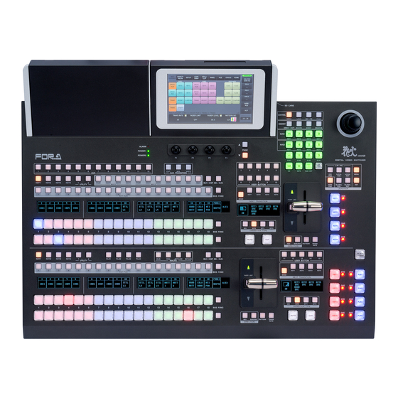
- Page 1 OPERATION MANUAL HVS-490 Digital Video Switcher HVS-492OU HVS-492WOU HVS-492ROU Operation Unit Edition - Rev. 1...
- Page 2 Edition Revision History Edit. Rev. Date Description Section/Page 2017/06/28 First edition 2017/07/28 Supported tally units. Sec. 25-2-5 2017/09/28 Added HVS-49SSD240G option. 16-4 Added HVS-49ED option. Supported external device connections (Editor, VTR 25-6 to 25-8 and VDCP) Appendix 3-6, Added menus to Web-based control pages. 3-8 to 3-12 2017/12/01 Supported HVS-492ROU...
- Page 3 Precautions Important Safety Warnings [Power] Operate unit only at the specified supply voltage. Caution Disconnect the power cord via the power plug only. Do not pull on the cable portion. Do not place or drop heavy or sharp-edged objects on the power cord. A damaged cord can cause fire or electrical shock hazards.
- Page 4 [Circuitry Access] Do not remove covers, panels, casing, or access the circuitry with power applied to the unit. Turn the power off and disconnect the power cord prior to removal. Internal servicing / adjustment of unit should only be performed by qualified personnel. Do not touch any parts / circuitry with a high heat factor.
- Page 5 OpenSSL This product includes software developed by the OpenSSL Project for use in the OpenSSL Toolkit (http://www.openssl.org/) Freetype Portions of this software are copyright © 2005 The FreeType Project (www.freetype.org). All rights reserved. Qt GUI Toolkit v4.8: LGPLv2.1 + Qt Company Qt LGPL Exception version 1.1 Copyright ©...
- Page 6 Upon Receipt Digital Video Switcher HVS-490 units and their accessories are fully inspected and adjusted prior to shipment. Operation can be performed immediately upon completing all required connections and operational settings. Check your received items against the packing lists below. Check to ensure no damage has occurred during shipment.
- Page 7 Other Option Units ITEM REMARKS HVS-AUX16A/16B/32A/64A (*1) Auxiliary Unit (Ethernet LAN connection) Tally Control Unit (Relay type) HVS-TALR20/32 (*2) (Hanabi Series Option) (RS-422 connection) Tally Control Unit (Open Collector type) HVS-TALOC20/32 (*2) (Hanabi Series Option) (RS-422 connection) (*1) Up to 12 units can be connected to the switcher LAN. (*2) Multiple HVS-TALOC / HVS-TALR configurations possible;...
-
Page 8: Table Of Contents
3-4-4. GPI I / O (Control Panel) ....................30 4. Switcher System Configuration ......................31 4-1. Network Settings ........................31 4-1-1. Factory Default IP Addresses ....................31 4-1-2. HVS-490 (MU) ........................32 4-1-3. Control Panel ........................32 5. Menu Operation ..........................33 5-1. Opening Menu Pages .......................33 5-1-1. - Page 9 6-8. Changing the Side Panel Image ....................45 6-9. Resize Function ........................45 7. Setting up Additional Inputs ........................47 7-1. HVS-100DI-A ..........................48 7-2. HVS-100AI ..........................48 7-3. HVS-100PCI ..........................49 7-4. HVS-100DO ..........................49 7-5. HVS-100AO ..........................50 7-6. HVS-100PCO ..........................51 7-7. HVS-49IO ..........................51 7-8. HVS-49AES ..........................52 8.
- Page 10 11-8-3. Clearing Direct Patterns ....................84 11-9. Modifying Patterns ........................85 11-9-1. Modified Pattern Data ......................85 11-9-2. WIPE Modify Example .....................85 11-9-3. DVE Modify Example .......................86 11-9-4. Resetting Modified Pattern ....................87 11-10. KEY IN/OUT Using Cut or Fade ...................88 11-10-1. Setting the KEY AUTO Button Function ................88 11-11.
- Page 11 15-3. Resetting Sub Effects......................117 16. Color Correction ..........................118 16-1. Assigning a Color Correction Channel ..................118 16-2. Adjusting Colors ........................118 16-3. Clip Adjustment ........................121 16-4. Resetting a Color Corrector Channel ..................122 17. Still and Clip Store ..........................123 17-1. Still Images (STILL) .......................123 17-1-1.
- Page 12 20-2. Sequence Group Operation ....................150 20-2-1. Assigning Buses to a Group ..................150 20-2-2. Creating, Editing and Playing Sequences ..............150 20-2-3. SEQUENCE Memory Operation ..................151 20-3. Deleting Sequence Memory Data ..................152 21. Macro Operations ...........................153 21-1. Recording Macros .........................153 21-2. Executing Macros ........................153 21-3.
- Page 13 27-3. Installed Options ........................205 28. Updating the System Software .......................205 29. Troubleshooting ..........................205 30. Specifications and Dimensions ......................206 30-1. Specifications ........................206 30-2. External Dimensions ......................210 30-2-1. HVS-490 ........................210 30-2-2. HVS-492OU ........................211 30-2-3. HVS-492WOU........................211 30-2-4. HVS-492ROU ........................212 Appendix 1. User Button Functions ......................213...
- Page 14 Appendix 2 GPI/GPO/TALLY Function Lists ..................217 Appendix 3. Web-based Control ......................220 3-1. Setup ............................220 3-2. Accessing Menu Pages......................221 3-3. Web Panel ..........................222 3-4. Event Memory .........................224 3-5. Macro ............................226 3-6. Wipe Pattern ...........................228 3-6-1. WIPE PATTERN - DIRECT PATTERN ................229 3-7.
-
Page 15: Prior To Starting
1. Prior to Starting 1-1. Overview HVS-490 is a Hanabi Series newest 2M/E switcher, which offers a rich feature set making it ideal for live staging, event applications, sports, news studios, OB vans, editorial offices, presentation venues and more. 1-2. Features Well-chosen standard features as well as various expansion options ... -
Page 16: Connection And Basic Operation
2. Connection and Basic Operation 2-1. Basic Connection Example (1) Connect video sources (SDI signals) from cameras or other video devices to the Main Unit. (2) Input a reference signal. Terminate the other connector with a 75-ohm terminator if it is not looped-through. -
Page 17: Power On
Supply power to the MU using the provided power cable and turn on the power switch located on the front panel. If a redundant power supply option is installed, turn on both power switches. HVS-490 DIGITAL VIDEO SWITCHER POWER 1... -
Page 18: Selecting System Signal Format
2-3. Selecting System Signal Format When powering on your unit for the first time, select a signal format as shown below. (1) A menu will appear on the screen when the system is powered on. (2) Tap the SETUP tab. (3) Tap SYSTEM, then FORMAT to display the menu as shown below (4) Turn control knob F1 to select the signal format used in the switcher. -
Page 19: Verifying Current Status
2-4. Verifying Current Status The HOME screen allows you to verify the M/E, FLEXaKEY and STILL status. In addition, some of these parameters can also be changed in the HOME screen. [HOME > M/E/FLEXaKEY] screen Open the [HOME > M/E/FLEXaKEY] screen. Tap the M/E1, M/E2, FLEXaKEY or UTILITY tab to display the tab screen ... - Page 20 UTILITY tab screen Parameter MASK EFF BKGD ANCILLARY Description Signal selection Usage status (See the table below.) Refer to 12-5-2, 11-12-8, 8-6 Symbol Meaning ✔ This is being used. Unavailable in the current setting. Unavailable Available [HOME > AUX] Screen To open the [HOME >...
-
Page 21: Panel Descriptions
Power and fan alarm. Lit red when an error occurs. In such cases, ALARM indicator power off the unit and consult your FOR-A supplier. The indicator is 1, 2 normally unlit. * Power Supply Unit 1 is standard and Unit 2 is optional. -
Page 22: Control Panel
Used for GPI output and Tally output. GPI /TALLY OUT 3-4-3 (25-pin D-sub, female) Used to connect external devices such as router. RS-422 3-4-1 2 ports (9-pin D-sub, female) Option Slots Used to install optional input/output expansion cards. Option Slot Used for HVS-49SSD240G. - Page 23 HVS-492ROU SD CARD CONTROL MENU LOCK KEY PRI PAGE MEMORY DIRECT PATT MACRO EVENT SEQUENCE M/E1 KEY1 KEY2 KEY3 KEY4 M/E2 ‚c‚d‚b KEY1 KEY2 KEY3 KEY4 + / - ALARM DIGITAL VIDEO SWITCHER PAGE POWER1 FLX1 FLX2 FLX3 FLX4 2.5D DVE POWER2 CLEAR...
- Page 24 Used to select background video sources for an M/E LINE1 M/E bus that is assigned to LINE 1. (Default setting: M/E1) LINE 1 Used to set up and perform background and / or key 11-3 transition block transitions in LINE 1. LINE 1 KEY Used to KEY1-4 transitions in LINE 1.
- Page 25 ALARM indicates the fan alarm status in the main unit. The indicator blinks red when an alarm occurs. In such a case, ALARM indicator power off the system and consult your FOR-A supplier. The POWER 1 indicator 27-1 indicator is normally unlit.
- Page 26 POWER Refer to Name Description Sec. Used for Main Unit (HVS-490) connection. (RJ-45) HVS LAN Use the control cable supplied with the OU to connect to the LAN HVS port on the OU. Used for GPI input/output and tally output.
-
Page 27: Option Slots
3-3. Option Slots All expansion cards for HVS-490 can be configured as shown below. Function expansion card modules should be installed into front side slots and I/O expansion cards into rear side slots. IMPORTANT For further details on system expansion (optional cards) and fan replacement, contact your FOR-A supplier. -
Page 28: Interfaces
3-4. Interfaces 3-4-1. RS-422 9-pin D-sub (female) with inch screws Connector Pin Assignment Table Pin No. Signal Name In/Out Description Frame ground Receive data (-) Transmit data (+) Signal ground Not used Signal ground Receive data (+) Transmit data (-) Frame ground RS-422 ports are used for external device connections. -
Page 29: Gpi / Tally Out
Pin 24 and 25 are shorted if a power failure occurs (or the unit is normally powered off). GPI IN/ALARM Circuit Switch or Relay Open collector External Device HVS-490 External Device HVS-490 3-4-3. GPI / TALLY OUT 25-pin D-sub (female) with inch screws ... -
Page 30: Gpi I / O (Control Panel)
3-4-4. GPI I / O (Control Panel) As factory default, the connector pin assignments are set as shown in the table below. 15-pin D-sub (female) with inch screws Connector Pin Assignment Table (15-pin D-sub, female) Pin No. IN/OUT Description M/E1 BKGD AUTO TRANS (default setting) M/E1 KEY1 AUTO TRANS (default setting) M/E1 KEY2 AUTO TRANS (default setting) -
Page 31: Switcher System Configuration
Use a network hub if adding external devices such as AUX units or computers to the switcher system. Direct Connection Use the supplied LAN cable to connect the HVS-490 LAN (HVS) port to the control panel HVS LAN port. (See Sec. 2-1. Basic Connection Example.) Using a Network Hub (1) Use the supplied LAN cable to connect the HVS-490 LAN (HVS) to a network hub. -
Page 32: Mu)
Open the [PANEL > NETWORK > NETWORK] menu and set the control panel LAN (HVS) address under IP ADDRESS and specify the HVS-490 to be controlled using LAN1 address under CONTROL MU IP ADDRESS. To configure multiple operation units to the switcher, each unit must have a unique IP address and OU ID. -
Page 33: Menu Operation
5. Menu Operation 5-1. Opening Menu Pages Menu access buttons in the touch panel are arranged in hierarchical order from top to bottom. Select a tab menu tab, then access level buttons to open a menu page where up to 4 parameters can be displayed. -
Page 34: User Buttons (Assigning Menu Shortcuts)
To Disable Menu Access Buttons Open [PANEL > UTILITY > UTILITY] menu PAGE 3 and turn MENU SHORTCUT to OFF. PANEL > UTILITY > UTILITY LOCK MODE THUMBNAIL MENU KEY BUS SHORTCUT SELECT LINK WAVE MANUAL 5-1-2. User Buttons (assigning Menu Shortcuts) Versatile user buttons on the control panel can be used as menu access buttons by assigning desired menu pages. -
Page 35: Function Button Settings
5-2-1. Function Button Settings Function button (F1 to F4) behavior can be modified as shown in [PANEL > UTILITY > UTILITY] menu. PANEL > UTILITY > UTILITY RENC TYPE RENC SPEED BUZZER BUZZER TONE VOLUME NORMAL NORMAL RENC TYPE Allows you to change the button twisting direction. RENC SPEED Allows you to increase / decrease the electrical response speed. -
Page 36: Copying / Swapping Settings
5-3. Copying / Swapping Settings The [COPY SWAP] menu allows you to copy or swap settings between MEs, MELites or, KEYs. Tap the COPY SWAP tab to open the menu. Ex.1: Copying Settings from M/E1BKGD to M/E2BKGD (1) Tap COPY. (2) Tap M1BG. -
Page 37: Returning Menu Settings To Default
5-4. Returning Menu Settings to Default 5-4-1. Returning Parameters to Default Press and hold the menu control push-button (F1 - F4) below each parameter to return their settings to factory default. If you need to reset parameters controllable from the JOYSTICK block to factory default, display parameters and press the DEF button. -
Page 38: Setting Up Video Sources
6. Setting up Video Sources 6-1. Adjusting Input Signal Levels 6-1-1. Proc Amp The HVS-490 switcher provides the following Proc Amp features. (1) Open the [SETUP > INPUT > PROCESS AMP] menu. (2) Turn F1 to select the input to be adjusted. -
Page 39: Mapping Video Sources To Bus Buttons
6-2. Mapping Video Sources to Bus Buttons Bus button rows, comprising 18 buttons for each row on HVS-492OU units, 22 buttons on HVS-492WOU and 12 buttons on HVS-492ROU, are used to select video sources. Primary and optional video inputs, internally generated signals (black, mattes, etc.) can be freely assigned to any buttons in the M/E1, M/E2 and AUX1-12 bus rows. -
Page 40: Using Different Mappings Between M/Es
6-2-1. Using Different Mappings between M/Es Different source mappings can be set for M/E1-2 and AUX1-12 bus rows. For example, to change M/E2 button assignments to different ones, proceed as follows. (1) Open the [PANEL > BUS ASSIGN > LEVEL1] menu and set M/E2 to ON and others to OFF. - Page 41 PANEL> BUS ASSIGN > LEVEL2 BUTTON SIGNAL INHIBIT COLOR PALETTE BLACK PALETTE00 How to use LEVEL1 and 2 (1) Press a bus button to activate the LEVEL1 setting. (2) Press and hold down 22 on the PST bus. (LEVEL2 settings are displayed on video name displays while 22 is pressed down.) Press 1 to 21 with 22 pressed to select LEVEL2 settings.
-
Page 42: Changing Video Source Names
6-3. Changing Video Source Names Input or internally generated video sources have default names (such as IN01-IN40, MATTE1, BLACK, COLOR BAR, etc.), which can be freely changed by the user. These source names are displayed on the video name displays and as titles in multiview images. To change video source names, proceed as follows. -
Page 43: Frame Synchronizer
(*1) Monochrome images (1-bit bitmap) are available. Save images in an SD card, insert the SD card to the slot and press F3 in the [SETUP > INPUT > NAME] menu. When a File Select dialog appears, select an image file and press LOAD to load the image. 6-4. -
Page 44: Matte Color Images
6-7. Matte Color Images Two matte color and one gradient matte signals (MAT1, MAT2 and GMAT) can be used as video sources and assigned to all bus buttons. IMPORTANT Before adjusting a color, display the matte on a monitor. To assign MATTE1 to Button 10, for example, select BTN10 under BUTTON and MAT1 under SIGNAL. -
Page 45: Changing The Side Panel Image
6-8. Changing the Side Panel Image The side panel image of 4:3 video can be changed as shown in the procedure below. (1) Open [SETUP > INPUT > SIDE PANEL] menu PAGE1. (2) Turn F1 to select an input to which side panels are to be added. (3) Turn F2 to select a video signal used for side panels. - Page 46 FORMAT (AUTO) IN01 (HD) RESIZE (OFF) (1080/59.94i) FORMAT (SD-SDI) IN13 (SD) RESIZE (4:3) (525/59.94i) FORMAT (SD-SDI) IN13 (SD) RESIZE (SQUEEZE) (525/59.94i) FORMAT (SD-SDI) IN13 (SD) RESIZE (LETTER) (525/59.94i) IMPORTANT The Resize function is automatically enabled when SD signals are input to the switcher in HD mode, and FORMAT in the [SETUP >...
-
Page 47: Setting Up Additional Inputs
7. Setting up Additional Inputs Additional input/output cards can be installed into SLOT A, SLOT B and 49IO SLOT. Install an HVS-49AES card to the dedicated 49AES SLOT. 49IO SLOT SDI INPUT HDMI HVS(OU) REF IN REF OUT GPI IN/ALARM GPI/TALLY OUT RS-422 GENLOCK... -
Page 48: Hvs-100Di-A
7-1. HVS-100DI-A HVS-100DI-A cards accept SDI signals. Normally, no menu settings are required for the cards. SDI INPUT SER. NO HVS-100DI-A Resize function The cards allow you to automatically enlarge SD images input to CH1 and CH2 to use as HD images in HD mode. -
Page 49: Hvs-100Pci
7-3. HVS-100PCI HVS-100PCI cards accept HDMI and VGA signals. Select a signal for Ch2 in the menu. HDMI/RGB INPUT SER. NO HVS-100PCI IMPORTANT The HDMI ports are not HDCP-compliant and cannot accept inputs from HDCP-protected devices such as Blu-ray players. NORMAL, FULL or ZOOM can be selected under RESIZE for 4:3 (aspect ratio) input signals. -
Page 50: Hvs-100Ao
SETUP > OUTPUT > AUX OUT SELECT OUTPUT OUTPUT AUX TRANS INHIBIT ENABLE AUX13 BLACK - - - - (SLOTA-1) SETUP > OUTPUT > AUX OUT SELECT OUTPUT OUTPUT AUX TRANS INHIBIT ENABLE AUX14 BLACK - - - - (SLOTA-2) 7-5. -
Page 51: Hvs-100Pco
7-6. HVS-100PCO HVS-100PCO cards output HDMI signals. HDMI (①) can be assigned to AUX13 and AUX17, and HDMI (②) and VGA (③) to AUX14 and AUX18. (See the figure below.) HDMI/RGB OUTPUT SER. NO HVS-100PCO Resolution, Aspect ratio and Audio output settings for the card can be set in the [SETUP > OUTPUT >... -
Page 52: Hvs-49Aes
7-8. HVS-49AES The card supports AES/EBU audio 4 stereo inputs (8 channels) and 4 stereo outputs (8 channels). Select between balanced (D-sub) or unbalanced (BNC) input using the slide switch on the card. An internal sampling rate converter enables to sync audio input to the system. Audio inserted on IN1-40, PGM, AUX outputs and CLIP1-4 can also be output from AES ports on the card. - Page 53 HVS-49AES input audio >> AUX outputs (AUX1-12) (1) Open [SETUP > OUTPUT > ANCILLARY] menu PAGE 2. (2) Turn F1 to select an AUX output and turn F2 to select AES IN. SETUP > OUTPUT > ANCILLARY OUTPUT SELECT ANCILLARY DATA AUX01...
-
Page 54: Video Outputs
8. Video Outputs Three output types are provided: M/E1 and M/E2 ports are for combined M/E images and both AUX1-6 and HDMI ports can output input video sources as well as combined M/E and multiview images. SDI INPUT HDMI HVS(OU) REF IN REF OUT GPI IN/ALARM... -
Page 55: Preview, Clean 1 And Clean 2 Images
8-1-2. PREVIEW, CLEAN 1 and CLEAN 2 Images Although preview images normally display next composited images, the images allow you to select the background and displayed key images, as well as clean images. The switcher does not provide dedicated preview or clean outputs. To output PREVIEW, CLEAN 1 and CLEAN 2, assign them to AUX, M/E 1 or M/E 2 output ports. -
Page 56: Key Out Signals
8-1-3. KEY OUT Signals KEY OUT signals (switcher processed key cut signals) can be assigned to AUX outputs and M/E OUT1 and 2. Various kinds of key cut signals can be used for KEY OUT sources. KEY OUT signals are useful for purposes such as checking key signals while processing chroma keys. -
Page 57: Changing Aux Output Images (Aux Transitions)
8-2. Changing AUX Output Images (AUX Transitions) AUX output images can be selected from all video sources, program, preview, clean and key out signals. In addition, simple video effects can be applied to AUX video switching. See Sec. 10-2 "XPT Re-entry" for details on re-entry video layers. See Sec. -
Page 58: Selecting A Video Using The Menu
8-2-2. Selecting a Video Using the Menu (1) Open the [SETUP > OUTPUT > AUX OUT] menu. (2) Turn F1 to select an AUX bus. (3) Turn F4 to set AUX TRANS ENABLE to ON. The set transition type in AUX TRANSITION block on the control panel is applied. - Page 59 For example, to output a UHD image composed of MV1 to MV3 and M/E2 PGM pictures from HDMI OUT1, set the menu parameters as shown below. SETUP > OUTPUT > HDMI OUT SELECT OUTPUT AUDIO UHD 4-SPLIT MODE HDMI OUT1 IN01 CH1/2 SETUP >...
-
Page 60: Adjusting Output Signal Levels
8-4. Adjusting Output Signal Levels 8-4-1. Proc Amp The switcher provides the following Proc Amp features, allowing you to adjust output signal levels. (1) Open the [SETUP > OUTPUT > PROCESS AMP] menu. (2) Turn F1 to select the output to be adjusted. (3) Turn F2 to turn ENABLE ON to enable the PROCESS AMP feature. -
Page 61: Safety Area Markers
8-5. Safety Area Markers Various markers for the safety area and screen center can be displayed on the desired output. (1) Open the [SETUP > OUTPUT > MARKER] menu. SETUP > OUTPUT > MARKER SELECT MARKER MARKER CENTER CROSS ENABLE TYPE AUX01 (2) Turn F1 to select an output bus. -
Page 62: Ancillary Data
8-6. Ancillary Data Ancillary data embedded in SDI input signals can be erased or passed through to outputs. (SD formats will be supported in the future.) As factory default, ancillary data, including audio, is set to pass through all combined M/E outputs, but not to pass through all AUX outputs. IMPORTANT Ancillary data in input video cannot be passed through if input frame synchronizers are set to ON for SDI input. - Page 63 (1) Open the [SETUP > BUS LINK > BUS LINK] menu PAGE 2. (2) Set MASTER BUS to M/E1PGM and SLAVE BUS to M/E1PST as shown below. (3) Set LINK MODE to NORMAL. SETUP > BUS LINK > BUS LINK LINK NO LINK MODE MASTER BUS...
-
Page 64: Trans Link
8-7-2. TRANS LINK The TRANS LINK function allows you to perform synchronous transitions. When a transition is performed on a master bus, the same transition is automatically performed on its slave bus. The following transition settings are shared. -CUT or AUTO transition -Transition Type, Pattern number and Transition Rate -Fader Level and Fader Limit (1) Open [SETUP >... -
Page 65: Bus Operation
9. Bus Operation 9-1. Control Panel HVS-492OU/492WOU/492ROU units are composed of two M/E controllers (LINE 1 and 2) and menu control or other blocks. ►See Sec. 3-2. “Control Panel” for details. HVS-492OU SD CARD CONTROL MENU LOCK KEY PRI PAGE MEMORY DIRECT PATT MACRO... -
Page 66: Assigning M/Es To Lines
LINE 1 is assigned to M/E1 and LINE 2 to M/E2 as factory default. These assignments, however, can be changed. To Lock the Control Panel Pressing the LOCK button in the CONTROL block disables the control panel operation and GUI control, except the LOCK button. -
Page 67: Selecting Video Sources
9-2. Selecting Video Sources Bus button rows on the control panel facilitate video source selection in the switcher. A single bus row comprises 18 bus buttons for HVS-492OU units, 22 for HVS-492WOU and 12 for HVS-492ROU and an M/E has three bus rows: PGM, PST and KEY/AUX for M/E1 and PGM, PST and KEY/FLEX for M/E2. -
Page 68: Selecting A Function To Bus Func Buttons
9-3. Selecting a Function to BUS FUNC Buttons The function for BUS FUNC buttons can be selected as shown below. ALARM POWER1 POWER2 WIPE AU X AU X TRANSITION KEY1 KEY2 KEY3 KEY4 OUT1 OU T2 OU T3 OU T1 OU T2 OU T3 BU S DISP SEL BUS... -
Page 69: Applying Colors To Bus Buttons
(3) Turn F2, F3 and F4 to create and save a color. PANEL > COLOR PALETTE > PALETTE00-29 PALETTE PALETTE00 Registering Signal Colors Signal colors can also be applied to bus buttons. To create signal colors proceed as follows: (1) Open the [SETUP >... - Page 70 Applying a Color to Unassigned Bus Buttons A desired light color can be set for a button to which no signal is assigned. (1) Open the [PANEL > BUS ASSIGN > ALL LEVEL] menu. (2) Turn F2 to select PALETTE or BLANK. If PALETTE is selected, select a specific color for each bus button under COLOR PALETTE in the [PANEL >...
-
Page 71: Melite Operations
10. MELite Operations MELites, simplified M/Es, can be assigned to LINE1 or LINE2. First, attach an AUX bus to an MELite. MELite mixed images can also be used as input sources on M/E1 and M/E2 (re-entry). FLEXaKEY1-4 can be displayed on MELite mixed images. Therefore the switcher can provide up to 4 M/E with a key for each. -
Page 72: Displaying Key Images
10-1-1. Displaying Key Images MELites can display up to 4 key images (FLEXaKEY1-4) in total. Open the [M/E FLEXaKEY > FLX1 > TRANS > ASSIGN] menu. Turn F1 to select MELite1. Selecting AUX05 for FLX2-4 in the same way allows you to display 4 keys on the mixed MELite1 images. -
Page 73: Transitions
11. Transitions <Transitions on LINE 1 and LINE 2 > Background, KEY1-4 and FLEXaKEY1-4 transitions can be performed on each M/E. If AUX1-12 are assigned to LINE 1-2, background and FLEXaKEY1-4 transitions are possible. Transitions setup by next transition bus selection Transitions using the CUT, AUTO button or fader lever CUT and MIX buttons dedicated to each keyer On-Air indicators for keys... -
Page 74: Transition Block
HVS-49IO option Operation Output BLACK Operation block Output bus Effects Keys connector TRANS LINE1 (default) M/E1PGM M/E OUT3-4 M/E1KEY1-4 M/E1 LINE2 M/E1OUT1-3 AUX7-12 FLX1-4 (LINE1) LINE1 M/E2PGM M/E OUT3-4 M/E2KEY1-4 PATTERN M/E2 LINE2(default) M/E2OUT1-3 AUX7-12 FLX1-4 LINE1 LINE2 AUX7-12 AUX7-12 AUX7-12 FLX1-4... -
Page 75: Black Transitions
LINE1 and LINE2 transition blocks Description Refer to Next transition bus selection Transition type and rate display for BKGD and KEY1-4 (HVS-492OU/492WOU) Displays BKGD, KEY and FLX transition rates and types on LINE1 and 11-3 LINE2. (HVS-492ROU) 11-4 Transition type selection 11-5 AUTO transition button for BKGD and KEY1-4 CUT transition button for BKGD and KEY1-4... -
Page 76: Background Transitions
11-3. Background Transitions This chapter explains how to perform background transitions using the M/E2 background assigned to LINE 2 as an example. CUT Transition (1) Select a video source in the PST bus block. (2) Press the BKGD button in the TRANSITION block. (3) Press CUT to perform the background CUT transition. - Page 77 ► See Sec. 11-7. “Pattern (WIPE/DVE) Transitions.” ► See Sec. 11-12-1. “Transition Rate.” ► See Sec. 11-12-2. “Using Fader Limit.” Checking Next Video and Transition To check the next video, monitor the Preview video by assigning M/E2PVW to an output. To check the current background video, monitor the Clean video by assigning M/E2CLN1 or M/E2CLN2 to an output.
-
Page 78: Key Transitions
11-4. KEY Transitions Key images are displayed on each M/E output screen. This chapter explains how to perform key transitions using M/E1KEY1 as an example. (1) Perform key setup for the KEY. (See Sec. 12. “KEY/FLEXaKEY.”) (2) Perform a desired transition referring to the below procedures. ... - Page 79 Pattern transition (1) Press KEY1 in the TRANSITION block. (2) Quickly press WIPE twice in the TRANSITION TYPE block. WIPE will light up and the [M/E FLEXaKEY > M/E1 > KEY1 > TRANS > TRANS] menu will appear. (3) Turn F4 to select a pattern. M/E FLEXaKEY >...
-
Page 80: Simultaneous Bkgd And Key Transitions
11-5. Simultaneous BKGD and Key Transitions Background and key transitions can be performed simultaneously. This chapter explains how to perform simultaneous BKGD, KEY1 and KEY2 transitions as an example. (1) Set transition types for the background, KEY1 and KEY2 to MIX or WIPE respectively. Select a pattern using the menu if set to WIPE. -
Page 81: Simultaneous Transition Of M/Es (Onstage)
11-6. Simultaneous Transition of M/Es (ONStage) The ONStage feature allows you to perform transitions of multiple M/E buses (M/E1, M/E2 and AUX1-12) simultaneously. The procedure example below shows how to perform M/E2 and AUX1 transitions at the same time. (1) Assign M/E2 and AUX1 to USER buttons located. USER 11 and 12 are used in this example. (See Sec. - Page 82 Tapping PATTERN NO. opens the following pop-up window and allows you to easily select a pattern. (5) Users can modify the pattern here to add a border, change the aspect ratio, the start position, and so on. See Sec. 11-9. “Modifying Patterns” for more details. Note that Direct Patterns can save/load modified pattern data.
-
Page 83: Direct Pattern Function
11-8. Direct Pattern Function The Direct Pattern Selection feature uses the number buttons (0-9) on the MEMORY block, to which patterns (WIPE or DVE type) previously registered can be recalled at the touch of a button. Up to 20 patterns can be registered. Pattern modification data can be added to direct patterns. The feature is useful for assigning frequently used patterns to number buttons. -
Page 84: Loading A Direct Pattern
If a number button (lit red) cannot be overwritten: Cancel the operation, change OVERWRITE from DISABLE to ENABLE in the [DIRECT PATTERN] menu, then overwrite the pattern setting. 11-8-2. Loading a Direct Pattern Let’s load DIRECT PATTERN10, which is saved in the previous chapter, to M/E2 KEY1. (1) Press DIRECT PATT in the MEMORY block. -
Page 85: Modifying Patterns
11-9. Modifying Patterns Preset patterns for pattern transitions can be changed or modified from their original patterns. There are two types of preset patterns, WIPE and DVE, which undergo different image processing methods and algorithms and provide different MODIFY menus: WIPE MODIFY and DVE MODIFY. 11-9-1. -
Page 86: Dve Modify Example
(7) Go to the next page in the menu to select a MATTE color. USE R BUT TON KE Y1 KE Y2 KEY3 KE Y4 BKGD FAD ER LI MIT NEXT T RANS IT ION WIPE EF F1 EFF2 T RAN SIT ION T YPE AUTO NO R/R EV PAT TERN... -
Page 87: Resetting Modified Pattern
Saving the Modify Pattern to a DIRECT Pattern The modified pattern can be saved to a DIRECT Pattern. Then let’s save Pattern 117 that was modified for M/E1KEY1 to DIRECT PATTERN 07. (1) Press DIRECT PATT in the MEMORY block. The [DIRECT PATTERN] menu appears and the multi-pad changes to DIRECT PATTERN mode. -
Page 88: Key In/Out Using Cut Or Fade
11-10. KEY IN/OUT Using Cut or Fade Key transitions can be performed not only through the BKGD AUTO button and fader lever, but also through key ON AIR and key AUTO buttons. (See figure below.) KEY1-4 ON AIR buttons (HVS-492WOU) Lit orange when 2.5D DVE is being used. -
Page 89: Aux Image Transitions
11-11. AUX Image Transitions AUX bus images can be switched using simple effects, such as fade and horizontal, vertical and both directional slides. The switcher provides wipe patterns from No. 0 to 99. The following example shows how to fade in/out AUX 1 images in 30 frames. (1) Quickly press AUX1 twice in the AUX block on the control panel. -
Page 90: Using Fader Limit
M/E FLEXaKEY > M/E2 > BKGD PGM > TRANS > TRANS TRANS RATE FADER LIMIT FADER LEVEL PATTERN NO. Set the transition rate for KEY1-4, AUX1-12 in the same manner. The setting range is 0 to 999 frames. Changing Transition Rate Units Transition rates are displayed in frames as factory default. -
Page 91: Adjusting Fader Offset
To Obtain the Current Fader Level You can quickly set the fader level for a background transition by first physically setting the fader lever to the point that you want the transition to finish. With the fader at this position, press and briefly hold down the FADER LIMIT button. -
Page 92: Endpoint Processing For Dve Transitions
Parameter Default Settings Description EFF BKGD MATTE (See Sec 11-12-8.) Specifies a color or image to be mixed. COLOR MIX Setting to ON sets the transition type back to OFF, ON ONCE MODE the previous one before color mix transitions. COLOR MIX 50.0 0.1 to 99.9... -
Page 93: Swapping The Auto And Cut Buttons
11-12-9. Swapping the AUTO and CUT Buttons The AUTO and CUT buttons in the TRANSITION block can be swapped using the menu. To do this, go to [PANEL > TRANS CONTROL > AUTO/CUT] menu PAGE 1 and turn F2 to change the setting to CUT/AUTO. -
Page 94: Key And Flexakey
12. KEY and FLEXaKEY The key feature enables you to superimpose titles and images onto background signals. Four key channels are provided for each M/E and four key types are available in all keyers: Luminance Key, Full Key, Bus Key and Chroma Key. Key Invert, Mask and DVE effects can also be added to keys. Furthermore, FLEXaKEY 1-4, whose background buses can be freely selected, are equipped as downstream keyers. -
Page 95: Creating A Luminance Key And Full Key
Full Key Full Key displays the key insert signal full-screen. Full key BOX(AND) mask Bus Key Bus Key, also called External Key, uses different images for Key Source and Key Insert. The background signal is cut out using Key Source and Key Insert fills in the cut out part of the signal. Bus key INVERT BOX(OR) -
Page 96: Creating Bus Keys
12-2. Creating Bus Keys Bus Keys use different signals for the INSERT SIGNAL and SOURCE SIGNAL. To create a Bus Key, select key insert and key source signals in the menus. Since selecting both signals in the menu takes time, the switcher KEY LINK function allows you to select an insert and source signal pair by selecting only an insert signal. -
Page 97: Key Quick Recall (Key Set: Input)
M/E FLEXaKEY > M/E1 > KEY1 > TRANS > SRC/INS 1/14 KEY TYPE INSERT TYPE INSERT SOURCE SIGNAL SIGNAL IN01 IN02 (1) Press a key bus button in M/E1 or M/E2 to select a key. (2) Once a key insert is selected on the KEY/AUX bus, the paired source is automatically set. POW ER1 POW ER2 C UT... -
Page 98: Adjusting Key Signal
12-3. Adjusting Key Signal Clip and Gain allows users to adjust the key signal and its composition over the background. Key transparency can also be adjusted. Adjust these parameters while monitoring keys on the screen by displaying keys on the Program, Preview or Clean video. (1) Open [M/E FLEXaKEY >... -
Page 99: Chroma Key Setup
12-4. Chroma Key Setup The built-in Chromakeyer has 4 channels in HD/SD mode and 3 channels in 1080/59.94p, 50p mode. Chroma keying allows key signal creation using a chroma component instead of a luminance component. This feature is mostly used to composite moving subjects such a person in a virtual background. - Page 100 The KEY1 image and crosshair will be displayed on the M/E1 PREVIEW screen and the current cursor position is displayed under POSITION X and Y. TIPS To make a crosshair cursor also appear on the M/E1 PGM screen, turn PGM OUT to ON in PAGE 3.
-
Page 101: Chroma Key Adjustments
12-4-2. Chroma Key adjustments If the desired result is not achieved using the automatic chroma key generation procedure, fine adjustments can be made as follows: Adjust chromakey edges to Adjust BACK COLOR to smooth edges. make the background image clear. Reduces color spills by adjusting KEY and FILL signals. -
Page 102: Masking Chromakeys
Adjusting chromakey edges <MATTE (KEY) > [EFFECT/MELite > CK1 > MATTE > FILTER] menu Parameter Description MATTE FILTER H Applies H/V filter in the LOW, HIGH or MID levels. MATTE FILTER V MATTE RECURSIVE FILTER Applies recursive temporal filter. [EFFECT/MELite >... -
Page 103: Mask And Invert
12-5. Mask and Invert Mask and Invert can be used for all keys. Bus key INVERT BOX(OR) mask 12-5-1. Inverting Key and Background (INVERT) Setting Invert to On inverts the key and the background images. Display the [M/E FLEXaKEY > M/E1 > KEY1 > TRANS > SRC/INS] menu PAGE 3. Set KEY INVERT to ON. - Page 104 UTILITY MASK Video inputs can be used for mask signals instead of Box. Inputs used for masks must be assigned to UTILITY1 or UTILITY2. Combined video signals such as program or multi-view cannot be used. (1) Create M/E1 KEY1. (2) Quickly press KEY1 twice in BUS SELECT to display the [M/E FLEXaKEY >...
-
Page 105: Key Edge
12-6. Key Edge The EDGE function allows users to add border type edges on KEY1-4. Three types of edges are available: Normal, Outline and Drop Shadow. The width, transparency, and color can be set for the edges. Shadow effects can also be added by changing the position of the edges. This chapter shows how to add a key edge using M/E1 KEY1 as an example. -
Page 106: Where Flexakey1-4 Appear
12-7-1. Where FLEXaKEY1-4 Appear FLEXaKEY1 and 2 images appear on combined M/E1 images and FLEXaKEY3 and 4 on M/E2 as factory default. Users can change the destination of FLEXaKEY1-4 to another bus. To do so, follow the procedure below. (1) Open the [M/E FLEXaKEY > FLX1-4 > TRANS > ASSIGN] menu. (2) Go to PAGE 9. - Page 107 Using the PRIORITY menu (1) Open the [M/E FLEXaKEY > M/E1 > KEY1 > TRANS > PRIORITY] menu. (2) Use F1 to F4 to set the key layer order. The top line represents the highest layer. M/E FLEXaKEY > M/E1 > KEY1 > TRANS > PRIORITY KEY1 KEY2 KEY3...
-
Page 108: Assigning Dve Channels
13. Assigning DVE Channels The HVS-490 has 16 DVE (2.5D DVE) modules as standard. (The number of available DVE channels depends on the system signal format.) These modules are applied to BKGD or Key buses as a DVE channel or DVE pattern to allow various advanced effects. However, DVE pattern and LINE DVE cannot be used simultaneously on a bus. -
Page 109: Line Dve On/Off Button
13-2-1. LINE DVE ON/OFF Button Assign the LINE DVE ON/OFF function to a bus button. In this example, the function is assigned to bus button 1 . (1) Open the [PANEL > BUS ASSIGN > LEVEL1] menu. (2) Turn F1 to select BUTTON 1. Turn F2 to select L-DVE under SIGNAL, then press F2. PANEL >... -
Page 110: Dve Channel Status Indication
13-3. DVE Channel Status Indication To verify how many DVE channels are being used on which buses, check the indicators and button indications as shown below. Background (M/E) Bus indications If a DVE type pattern is selected for the background and WIPE in the transition block is lit, one DVE channel is used. -
Page 111: Dve Effects
14. DVE Effects This chapter shows how to apply DVE effects to M/E2KEY1 as an example. Assume that LINE DVE is set to ON for M/E2KEY1. (See Sec. 13-2-2. “Enabling LINE DVE on a BUS.") In this example, the KEY1 image, to which DVE effects is applied, is called “DVE image.”... -
Page 112: How To Use The Joystick
14-1-1. How to Use the Joystick The joystick controls Position and Size in the WIPE MODIFY and DVE MODIFY menus. The following example shows how to set bus and parameter settings using the joystick. Changing POSITION X, Y and SIZE for M/E2KEY1 in the DVE MODIFY menu (1) Tap on the button in the upper right corner of the menu screen to pop-up the JOYSTICK MENU window. - Page 113 The following buttons in the JOYSTICK block allow you to select target parameters for the joystick. 2.5D DVE LOCAL LOCAL MENU WIPE GLOBAL GLOBAL JOYSTICK Item Description Allows you to change the DVE POSITION and SIZE parameters DVE POS using the joystick even if another menu page is opened. Allows you to change the DVE LOCAL POSITION parameters LOCAL POS using the joystick even if another menu page is opened.
-
Page 114: Rotation
14-2. Rotation In addition to position and size changes, users can add rotational effects to DVE images. Tap on ROTATION in the bottom menu buttons to display the menu. Remember that DVE images are located at their POSITION X and Y coordinates, with the origin of the axes located at the center of the screen. -
Page 115: Size(X, Y) And Fade
14-4. SIZE(X, Y) and FADE SIZE (X, Y) SIZE X, Y in PAGE 2 allows you to change the aspect ratio of DVE images. M/E FLEXaKEY > M/E2 > KEY1 > MODIFY > DVE POS/SIZE 2/12 SIZE-X SIZE-Y FADE 1000 1000 The figures below show examples when POSITION is set to (0, 0) and SIZE 1,000. -
Page 116: Sub Effect
15. SUB EFFECT Sub effects such as Mono Color, Defocus, Paint and Mosaic can be added to video images. Up to 4 Sub Effect channels are available in HD/SD mode. Sub Effect channels can be output from AUX buses by assigning as SUBEFF1-4, and used for video sources such as Key Source/Insert and Background images. -
Page 117: Resetting Sub Effects
Parameter Description Allows users to enable the freeze effect function. FREEZE Users can select either frame freeze or field freeze. Allows users to enable strobe effects. STROBE Increasing the value increases the light flashing interval. If set to FILM A or FILM B, a different film effect is applied NEGA Setting to ON makes an image negative by reversing all luminance levels. -
Page 118: Color Correction
16. Color Correction The switcher provides 4 color correction channels that can be assigned to inputs. In addition, Clip adjustment allows users to set signal level limits for all color correction outputs. The following features are available: Max. 4 color correction channels ... - Page 119 Page Parameter Description Default Setting range Page 2 R / G / B Adjusts R, G and B. 100% 0% to 200% WHITE Page 3 R / G / B Adjusts R, G and B. 100% 0% to 200% BLACK CURVE Selects gamma curve.
- Page 120 (2) The figures below illustrate the change in signal waveform when the BLACK level is adjusted along the R axis in balanced or differential mode. These changes will also be applied to the G or B axis. BALANCE mode When set to a negative value: Default When set to a positive value: DIFFERENTIAL mode...
-
Page 121: Clip Adjustment
16-3. Clip Adjustment Signal level thresholds for all color correction outputs (Clip adjustment) can be adjusted in Y/C (YBR) or RGB mode. If Clip adjustment is disabled (ENABLE to OFF), default values are applied to output signals. <To Set Clip in Y/C Mode> (1) Open [SETUP >... -
Page 122: Resetting A Color Corrector Channel
Y/C mode Y Black Clip Y White Clip Adjustable range: -7 to 50% Adjustable Range 50 to 109% Default setting: -7%) 109% Default setting: 109% 100% 100% Y White Clip level range Y Black Clip level range 100% color bars when 0% Black 100% color bars when 100% white ... -
Page 123: Still And Clip Store
17. Still and Clip Store The switcher can capture and memorize still images from the switcher input and output video, and record and play back the output video as video clips. In addition, input video can display frozen images by capturing an input video and saving it to the Frame Synchronizer buffer. (INPUT STILL function) (See Sec. -
Page 124: Selecting Still Images In V-Ram
To automatically update thumbnails, select AUTO under THUMBNAIL in [PANEL > UTILITY > UTILITY] menu PAGE 3. They can be loaded to still memory buffers from SD cards. (See Sec. 22. “File Operations.”) 17-1-2. Selecting Still Images in V-RAM Still images can be loaded directly from V-RAM. The following procedure shows how to load a still image stored in V-RAM to STILL 2. -
Page 125: Selecting Video Clips In V-Ram
(3) Tap here, then turn F2 to change to CLIP. (4) Go to PAGE 2. (5) Tap on REC READY to be on recording standby. (If the number of recording frames are predetermined, turn F4 to set the number under OUT.) (6) Tap on RECORD (red circle) to start recording. -
Page 126: Playing Video Clips
(2) Tap the CLIP icon in STILL2. (3) Tap to select a clip in the pop-up dialog. The clip will be immediately loaded to STILL 2 if DIRECT LOAD is checked. (4) Otherwise, tap LOAD. The clip will be loaded. 17-2-3. -
Page 127: Cg Wipe
17-2-4. CG WIPE CG Wipes are video effects that allow you to play movie files according to background transitions. CG Wipes can be created using a modified pattern. CG WIPE videos are composed using an M/E key. The procedure example below shows how to play a CG WIPE on the M/E1 background under the conditions listed in the table. -
Page 128: Still Image Display Using Fs Buffer (Input Still)
17-3. Still Image Display Using FS Buffer (INPUT STILL) The switcher standard inputs can display still images by capturing input video or uploading still images to frame synchronizer buffers (INPUT STILL) from SD cards. (See Sec. 22. “File Operations.”) The following example shows how to capture and display a still image on IN05. 17-3-1. -
Page 129: Storing Still And Video Images (Hvs-49Ssd240G)
17-4. Storing Still and Video Images (HVS-49SSD240G) Still and clip memory in the switcher SSD (option) SD card COPY RESTORE STILL1 (17-4-2) STILL1-4 (17-4-1) STILL4 INPUT STILL IN01-40 INPUT STILL AUTO BACKUP JPEG IN01 COPY CLIP1-4 (17-4-1) (17-4-2) IN40 CLIP1 LOAD JPEG CLIP4... -
Page 130: Copying Stills/Clips (Between Sd Card And Ssd)
Loading SSD Backup Images on Startup (1) Open [STILL/CLIP > STILL/CLIP] menu or [STILL/CLIP > INPUT STILL] menu. (2) Turn F1 to select a still channel or turn F2 to select a clip channel. (3) Go to PAGE 2 for stills or PAGE 4 for clips. (4) Set RESUME to ON to load the still images at startup. -
Page 131: Loading Stills And Clips (From Ssd To Switcher)
17-4-3. Loading Stills and Clips (from SSD to Switcher) Still pictures and video clips can be loaded from the SSD to the STILL or CLIP memory in the switcher in the same manner as described in Sec. Let’s load the still image copied from the SD card to STILL 3. -
Page 132: Multiview Output
18. Multiview Output The multiviewer allows you to monitor multiple images such as video sources input to the switcher and internally generated or combined images on the same screen. The switcher provides 3 multiviewer channels (MV1-MV3*), with each output having various types of split displays: 2, 4, 5, 7, 9, 10, 11, 13 and 16 way. -
Page 133: Selecting The Screen Layout
18-2. Selecting the Screen Layout (1) Quickly press MV1 twice in the KEY/AUX block to display [SETUP > MULTI VIEWER > MV1] menu PAGE 1. (2) Turn F1 to select the screen layout. SETUP > MULTI VIEWER > MV1 BORDER 18-3. -
Page 134: Audio Level Meter
(4) Turn F3 to select background and position of titles. TITLE AREA setting Description WIDE Spreads the title background to the width of the screen. NORMAL Adjusts the width of the title background to fit the title. Title Backgrounds are not displayed. (5) Go to PAGE4 and turn F2 to select the title font size and use F3 and F4 to adjust the horizontal and vertical positions. -
Page 135: Safety Area
18-4-3. Safety Area (1) Open [SETUP > MULTI VIEWER > MV1] menu PAGE 5. (2) Turn F1 to select a sub-screen. (3) Turn F2 to select HOOK or BOX for the screen. (4) Turn F3 to select the safety area size. SETUP >... -
Page 136: Event Memory
19. Event Memory The switcher can save settings as a data set. This function is called Event Memory. Event Memory allows you to quickly recall saved panel settings at any time when needed. The MEMORY block is used to save and recall events. In addition, data to be stored to or loaded from events can be selected in the menu. -
Page 137: Recalling Events
Ex) To Save Settings to EVENT 23 Successively press EVENT > PAGE > 2 > STORE > (Select data in the menu.) > 3. If Events are Already Saved: When EVENT is pressed, the number buttons light up if events are saved. If you press a button where an event is already saved, it flashes. -
Page 138: Using The Recall Button
19-2-2. Using the RECALL Button To Recall Events (fastest method): (1) Press EVENT in the MEMORY block. CONTROL MENU LOCK KEY PRI PAGE (2) Press the number button where the needed data is stored. M EMORY (3) Press RECALL. DIRECT PATT MACRO EVENT... -
Page 139: Transitions Using Event Recall
19-2-3. Transitions Using Event Recall The DURATION parameter in the EVENT menu allows users to set the time duration (transition rate) it takes to load events. With this time duration, transition sequences of two steps (statuses before and after recalling events) can be performed. The two images (keyframes) before and after recalling events that appear on program screens are automatically interpolated to create a smooth transition in the same way as the Sequence feature. -
Page 140: Overwrite Protection
19-3. Overwrite Protection (1) Press EVENT in the MEMORY block. (2) Turn DIRECT to OFF so as not to load events. (3) Press the number (memory) button to be set. The button goes from lit to flashing the [EVENT RECALL] appears. When EVENT is pressed, number buttons light up if they have setting data. -
Page 141: User Default Setting
19-5. User Default Setting The event store data can be changed from the factory default settings (M/E1 and M/E2). (1) Press EVENT in the MEMORY block to display the [EVENT MEMORY] menu. (2) Press STORE in the keypad. (3) Select data to be stored in the menu screen. (4) Go to [EVENT MEMORY] menu PAGE 2. -
Page 142: Sequence Function
20. Sequence Function A sequence is a function for joining individual images into a sequential video and recalling it for playback in a single operation. Each sequence is composed of video frames called steps. To make sequences, create an initial step and save it to the sequence working memory, then create the next step and to save to the working memory and so on. -
Page 143: Basic Sequence Operations
20-1. Basic Sequence Operations The HVS-490 allows you to create sequences based on which buses are to be used. For example, to create sequences of the M/E1, create a group of M/E1 BKGD and M/E1 KEY1 to 4, then create and store sequences based on the group. -
Page 144: Storing Sequences
Now the sequence is created and saved in the working memory. Note that DVE channel switching may cause video distortion. The switches will happen in cases when turning LINE-DVE On/Off, or changing the transition type or pattern. 20-1-2. Storing Sequences The following procedure shows how to store the M/E1 BKGD sequence just created to Sequence Memory 10. -
Page 145: Playing Back Sequences
20-1-3. Playing Back Sequences The following procedure shows how to load and play the sequence stored in Sequence Memory 10. CONTROL (1) Open the [SEQUENCE > FILE] menu. MENU LOCK KEY PRI PAGE (2) Press PAGE in the MEMORY block. M EMORY (3) Press 1 on the keypad to select PAGE 1. -
Page 146: Playing Back Sequences Using Advanced Settings
20-1-4. Playing Back Sequences Using Advanced Settings Playback settings can be set in the [SEQUENCE > EDIT] menu pages, PAGE1-3. SEQUENCE > EDIT GROUP TRANS GROUP1 AUTO AUTO SEQUENCE > EDIT GROUP FADER LOOP GROUP1 SEQUENCE > EDIT GROUP OFFSET OFFSET GROUP1 The following settings are available:... -
Page 147: Editing Sequences (Adding Or Inserting Steps)
20-1-5. Editing Sequences (Adding or Inserting Steps) This chapter explains how to copy, paste and delete steps. The operational example below shows how to load Sequence Memory 10 (created in Sec. 20-1-1) and edit the sequence by adding and overwriting steps. Sequence Memory 10 data Store the edited sequence to Sequence Memory 1. -
Page 148: Editing Sequences (Step Copy And Step Delete)
Tapping ADD adds a step behind the current step and the total duration is increased. Tapping INS add a step behind the current step but the total duration is the same as before. TOTAL DURATION Insert TOTAL DURATION Playing the Sequence (7) Tap PLAY/PAUSE to play the edited sequence. -
Page 149: Editing Sequences (Step Settings)
20-1-7. Editing Sequences (Step Settings) In the [SEQUENCE > EDIT] (4/4) menu, detailed step settings can be performed. SEQUENCE > EDIT STEP INTERP BREAK STEP01 SMOOTH INTERPOLATION mode between Steps The INTERPOLATION mode allows you to smooth movements between steps. LINE (Default) SMOOTH Linear interpolation between... -
Page 150: Sequence Group Operation
20-2. Sequence Group Operation Sequence Group in the HVS-490 is a strong tool for sequence bus operations and allows you to flexibly manage video buses in sequences. Once buses are grouped, sequence operations using multiple buses can be performed only by selecting a group. -
Page 151: Sequence Memory Operation
20-2-3. SEQUENCE Memory Operation A sequence having multiple bus data to Sequence Memory 3 (1) Open the [SEQUENCE > FILE] menu. (2) Press PAGE in the MEMORY block. (3) Press 0 on the keypad. (4) Press STORE on the keypad. (5) Verify that all required buses are selected in the [SEQUENCE >... -
Page 152: Deleting Sequence Memory Data
SEQUENCE > FILE EDIT NAME OVER WRITE STAND-BY BUS SELECT M1BG M1BG S00 DISABLE Parameter Setting Description EDIT BUS SELECT (Available buses) Selects a bus for editing. NAME Changes bus names. (See the previous page.) Disables overwriting of bus data. DISABLE (default) A locked key icon is displayed on bus buttons in the OVER WRITE... -
Page 153: Macro Operations
21. Macro Operations The Macro function allows users to perform a sequence of recorded operations with the single push of a button. The keypad is used to record and execute macros. Macro memory data can be backed up and restored from SD cards. See Sec. 22 "File Operations" for more details. Macros cannot be edited in the menu screen, but in web browser control screens. -
Page 154: Macro Memory Operation
21-3. Macro Memory Operation 21-3-1. Overwrite Protection (1) Press MACRO in the MEMORY block to display the MACRO menu. (2) Press PAGE above the MEMORY block, then press 0 or 1 to specify the memory page. (3) Press the memory (number) button. (4) Go to PAGE 2. -
Page 155: Copying, Moving And Exchanging Macro Data
To Delete a Macro Page (1) Press MACRO in the MEMORY block to display the MACRO menu. Go to PAGE 3. (2) Turn F2 to select a page, then press F2. MACRO DELETE PAGE DIRECT CLEAR CLEAR To Delete All Macro Data Turn F2 to select ON under PAGE CLEAR, then press F3. -
Page 156: Macro Execution Buttons
21-4. Macro Execution Buttons 21-4-1. Assigning Macros to KEY/FLX Bus Buttons Macros can be assigned to KEY/FLX bus buttons. The example below shows how to execute Macro 00 using Bus Button 1 Assigning Macro 00 to Bus Button 1 (1) Open the [PANEL >... -
Page 157: Macro Attach And Macro Detach
(5) Press a KEY/FLX bus button to store the macro data under the corresponding number. The bus button also becomes the macro execution button. When bus buttons are pressed, they light up if they have data. To overwrite the data to a lit button, press the button so that it changes from lit to flashing, then press the button again. -
Page 158: File Operations
22. File Operations The switcher is capable of storing operational data, such as system and bus setting data, still images, WIPE and DVE modifications and event data, to SD cards and of recalling and downloading previously saved data for application to production operations. 22-1. -
Page 159: Loading Data (From Sd Card To Switcher)
FILE > SAVE SELECT TYPE SOURCE EXEC FOLDER DATA.all Do not remove the SD card while the access lamp is flashing. The time at which data is saved to an SD card is also recorded according to the switcher internal clock. Set the date and time if it is improperly set. -
Page 160: Loading Image Files
22-4-3. Loading Image Files JPEG. TARGA or BITMAP image files can be loaded to STILL1-4 and INPUT STILL buffers using SD cards. The following procedure explains how to download a JPEG file to STILL1 as an example. (1) Insert the SD card in which the JPG file is stored, into the card slot. (2) Open the [FILE >... -
Page 161: Adding Audio To Sequential Image Files
(8) Tap YES on the pop-up screen to load the files to the switcher as a clip. FILE > LOAD SELECT TYPE AUDIO OFFSET EXEC FOLDER CLIP CLIP1 Sequential Image File Names Folder name XXXXXXXX XXXXXXXX Up to 16 alphanumeric characters (Files whose name have 17 or more characters cannot be loaded.) Prepare sequential file names in the following name format. -
Page 162: Editing Data In Sd Card
Loading the created clip (8) In the same menu page, turn F1 to select the created clip by specifying the folder. (9) Press F4. Tap YES on the pop-up screen to load the clip to the destination where the audio file was loaded. -
Page 163: Sending / Receiving Data To/From Pc
PCs, and send video clips in the clip memory and INPUT STILL images to computers, through an Ethernet The FTP protocol is used for transferring files between the switcher and computers. The main unit (HVS-490) works as an FTP server. 22-6-1. Setup before Connection ... - Page 164 (clip1) Used for uploading movie files to STILL1. | (clip4) Used for uploading movie files to STILL4 (INPUT_STILL) (STILL_IN01) Used for uploading still image files (INPUT STILL) for IN01 | (STILL_IN40) Used for uploading still image files (INPUT STILL) for IN40 (EVT) Event No.
-
Page 165: Sending / Receiving Still Images
(4K_STILL_INPUT) (STILL_IN01) Used for uploading 4K still image files (INPUT STILL) for IN01 | (STILL_IN10) Used for uploading 4K still image files (INPUT STILL) for IN10 (STILL) To send image files to V-RAM, specify this folder. (CLIP) Video clip upload folder to be stored in V-RAM (SSD) SSD storage (HVS-49SSD240G option) (4K_STILL) -
Page 166: Sending Images To Clip Memory
(2) Select the image to be uploaded and drag and drop it to a still folder (STILL1 to STILL4) of the FTP server. It takes about 30 seconds to complete receiving data. Then display the still image in the monitor by operating the switcher to check that the still image is properly sent. -
Page 167: System Setup Settings
1080PsF/29.97, 25, 24, 23.98 Switches crosspoints at the same time regardless of setting. 23-3. Reference Signal Settings The HVS-490 switcher provides reference input, loop-through and output connectors in the GENLOCK section on the rear panel. Adjusting input signal timing Horizontal correction range of SDI input signals can be shifted by changing the H PHASE setting. -
Page 168: Setting Date And Time
To set SDI minimum delay against REF IN to 1H (NTSC/PAL to 2H): SDI signal format H PHASE setting SDI signal correction range 1080/59.94i -930 -0.9H to +0.1H 1080/50i -1150 -0.9H to +0.1H 1080/24PsF -1200 -0.9H to +0.1H 1080/23.98PsF -1200 -0.9H to +0.1H 1080/29.97p -930... -
Page 169: Setting Time Using Sntp (Time) Server
23-4-1. Setting Time Using SNTP (Time) Server The switcher time can be synchronized to a time (SNTP) server using the Simple Network Time Protocol (SNTP). To synchronize the time to a SNTP server time, enter the IP address of your SNTP server, set the time zone, then update the time manually. -
Page 170: Control Panel Setup
24. Control Panel Setup For bus button assignments, refer to Sec. 6-2. “Mapping Video Sources to Bus Buttons.” For control panel connection, refer to Sec. 4. “Switcher System Configuration.” 24-1. Buzzer (1) Open the [PANEL > UTILITY > UTILITY] menu. (2) Use F3 and F4 to adjust buzzer volume and tone. -
Page 171: User Button
HVS-492ROU 24-3. USER Button User buttons can be assigned to specific menu pages and used as shortcuts or specific function buttons. The following 15 user buttons on HVS-492OU, 20 on HVS-492WOU and 6 on HVS-492ROU are available. HVS-492OU HVS-492WOU HVS-492ROU SD C ARD CON TROL MEM ORY... -
Page 172: Reboot And Initialization
(4) Turn F3 to select a menu page or a function, then press F3. PANEL > USER BUTTON > USER BUTTON USER BUTTON TYPE FUNCTION BTN01 NONE NOT ASSIGN If Menu Shortcut is Set: Pressing the button opens the assigned menu page. ... -
Page 173: External Device Connections
Editor 25-6 LAN (EXT) RS-422 25-7 RS-422 VDCP 25-8 LAN (EXT) Sending alarms (ALARM) GPI IN/ALARM 3-4-2 (*1) MU: HVS-490, OU: Control panel EDITOR Connection Example SDI INPUT HDMI HVS(OU) REF IN REF OUT GPI IN/ALARM GPI/TALLY OUT RS-422... -
Page 174: Gpi Control
NONE NONE 25-1-2. GPI OUT The GPI/TALLY OUT connector on the HVS-490 provides GPI outputs. (See Sec. 3-4-3. “GPI/TALLY OUT Connector.") (1) Open the [SETUP > GPI TALLY > GPI OUT] menu. (2) Select the pin number or flag number under PIN/FLAG. -
Page 175: Gpi I / O (Control Panel)
TIPS The status of user flags can be viewed in the [SETUP > GPI TALLY > USER FLAG] menu. 25-1-3. GPI I / O (Control Panel) To assign GPI functions to GPI IN/TALLY OUT connector pins on the Control Panel, proceed as follows. -
Page 176: Tally Output
25-2. Tally Output Tally information can be output from the GPI /TALLY OUT connectors. Tallies can be assigned to the GPI/TALLY OUT connector on the HVS-490. (See Sec. 25-2-2. "Tally Output Settings (GPI /TALLY OUT)." for details on settings.) Tally information can also be output via the GPI I/O connector on the control panel. -
Page 177: Tally Output Settings (Gpi /Tally Out)
25-2-2. Tally Output Settings (GPI /TALLY OUT) To change GPI/TALLY OUT connector pin assignments (See Sec. 3-4-3. “GPI I/O Connector“), proceed as follows. (1) Set tally colors for output buses. (See Sec. 25-2-1. “Tally Color Settings.”) (2) Open the [SETUP > GPI TALLY > GPI OUT] menu. (3) Turn F1 to select the pin number. -
Page 178: Ext Tally
25-2-4. EXT TALLY Five external tallies allow users to freely notify the system information to external devices. Their tally colors are also set in the [SETUP > GPI TALLY > TALLY COLOR] menu. (1) Open the [SETUP > GPI TALLY > EXT TALLY] menu. (2) Turn F1 to select an EXT TALLY number. -
Page 179: Tally Output Settings (Tally Units)
(2) Turn F1 to select PORT2. (3) Turn F2 to select TALLY. Set the parity to EVEN. Set the baud rate to 38,400 bps. (4) Reboot the HVS-490. (See Sec. 24-4. Reboot and Initialization.) SETUP > SYSTEM > RS-422 SELECT... -
Page 180: Router Control
The switcher can connect and control a router. Router crosspoint switches can be performed on the switcher's control panel. The router control is based on the HARRIS Pass-Through protocol. In addition to router control, video titles on the router can be handed to the switcher if a FOR-A MFR series router is connected. (*1) Manageable number of sources, destinations and levels are: Manageable max. -
Page 181: Setting Mfr Link
(3) Turn F2 to select 1 under DST (destination). The currently connected source is displayed under SRC (source). (4)Turn F3 to select 2, and press F3 to switch the source. The HVS-490 sends the crosspoint switch command to the router. -
Page 182: Crosspoint Switches Using Bus Buttons
25-3-4. Crosspoint Switches using Bus Buttons To execute the following commands using Bus Buttons on LINE 2: Select a router level. Connect Source channel 2 to Destination channel 1. Connect Source channel 4 to Destination channel 2. * Router Level setting in the menu is applied to bus button crosspoint switches. First change LINE 2 to ROUTER mode, then switch crosspoints. -
Page 183: Simultaneous Switching (Take Function)
25-3-5. Simultaneous Switching (TAKE function) Multiple crosspoints (destination/source pairs) can be switched simultaneously in the menu using stored crosspoint data. Simultaneous switching using the menu (1) Open the [ROUTER > MANUAL CONTROL] menu PAGE 2. (2) Turn F1 to select a level. (3) Turn F2 to select a destination. -
Page 184: Router Link
OPTION SLOT B BUS FUNC Control panel HVS-490 rear panel Router link buttons on the A bus Router Link function can be applied to each bus. If assignments are different for A, B, PGM and PST buses, to use the ROUTER LINK function in another bus, a router connection is required. - Page 185 PANEL > BUS ASSIGN > LEVEL1 BUTTON SIGNAL INHIBIT COLOR PALETTE BTN03 RX003 PALETTE00 (3) Open [SETUP > ROUTER > XPT LINK] menu PAGE 2. Select M/E1 A BUS under BUS SELECT. Set the switcher input and the router destination channel as shown below. SETUP >...
-
Page 186: Mfr-Talm Connection
25-3-7. MFR-TALM Connection When working with a FOR-A MFR Series router, MFR-TALM Tally Manager allows you to accelerate tally and title (video name) links. If configuring an MFR-TALM, crosspoint switching is performed between the switcher and router, and tally and title links are made between the switcher and tally manager. -
Page 187: Tsl Umd Protocol
Use the LAN EXT port on the HVS-490 units for sending / receiving TSL messages. Receiving Signal Names (TSL IN) The HVS-490 can receive source signal names using TSL UMD 5.0 by setting in the [SETUP > TSL > TSL IN] menu. SETUP > TSL > TSL IN... -
Page 188: Aux Bus Control Box (Hvs-Aux16A/16B /32A/64A)
To connect to HVS-490 units, use ID1 to ID12. (Default setting: ID1) The ID numbers should not be duplicated when connecting to a switcher. In an AUX box, specify the IP address of the HVS (OU) port on the HVS-490 as a switcher IP address. (Default: 192.168.0.10) ... -
Page 189: Assigning Actions To Aux Box Buttons
25-5-2. Assigning Actions to AUX Box Buttons Actions can be assigned to AUX Box buttons. (Ex 1) An AUX Box can change crosspoints on the router connected to the switcher. (Ex 2) Example 1) To assign the action “Output the M/E1PGM video from the AUX3 bus” Two methods are available: ... - Page 190 (3) Go to PAGE 2 and set Button 2 on UNIT 2 as shown below. SETUP > AUX UNIT > UNIT2 BUTTON FUNCTION TARGET SELECT ROUTER BTN02 SRC05 (4) Press Button 2 on the UNIT 2 AUX box. The DST (Destination) 3 is switched to SRC (Source) on the connected router.
-
Page 191: Adjusting Light Levels For Aux Box Buttons
BLACK IN01-40 STILL1-4 STILL1-4 KEY COLOR BAR WHITE M/E1-2 PGM MATTE1-2 M/E1-2 PST GMAT M/E1-2 A BUS CK1-4 FILL M/E1-2 B BUS CK1-4 KEY Selects the output signal. M/E1-2 KEY1-4 INSERT SUBEFF1-4 M/E1-2 KEY1-4 SOURCE M/E1-2 PGM FLX1-4 INSERT M/E1-2 PVW FLX1-4 SOURCE M/E1-2 CLN1 M/E1-2 CLN2... -
Page 192: Setting Lock Button On Aux Boxes
With these settings, HVS-AUX16A / 16B / 32A units can use additional 16/32 buttons using the SHIFT/TAKE button. Refer to the table below for details on how to use this button. Parameter Default Setting Description Additional buttons cannot be used. Pressing the SHIFT/TAKE button enables SHIFT and TOGGLE SHIFT... -
Page 193: Editor Control
25-6. Editor Control The switcher can be controlled from an editor through an RS-422 interface. The HVS-2000ED software option is required for editor control. 25-6-1. Editor Control Settings (1) Open the [SETUP > EDITOR > EDITOR] menu. (2) Select a protocol under TYPE between DVS (SONY DVS/BVS series compatible) and GVG-K/Z. -
Page 194: Editor Connection Settings (Rs-422 Port)
25-6-3. STATUS REPORT Status reports are available via DVS protocol. When the Status Report feature is enabled, crosspoint or transition type changes on the HVS-490 switcher are notified to the editor. See a separate manual on HVS-49ED protocol commands for more details. -
Page 195: Vtr Control
System Configuration Example (1) Connect HVS-490 to a VTR using an RS-422 port and configure the port. (2) Assign a VTR channel to the RS-422 port. (See Sec. 25-7-1.) (3) Control the VTR using the VTR menu (see Sec. 25-7-2) or using USER buttons (see Sec. -
Page 196: Vtr Control
25-7-2. VTR Control Open the [SETUP > VTR > VTR1 (VTR2)] menu. Item Description Sets the CUE UP time in PAGE 2. To set the time, turn F1 to set the CUE UP button time, then tap the CUE UP button. Timecode / Displays the current VTR state on the left side and playback state on playback status... -
Page 197: Vdcp Operation
System Configuration Example (1) Connect a VDCP device to HVS-490 via RS-422 or LAN. If using RS-422, assign a VDCP channel to an RS-422 port and set communication settings. If using LAN, change the VTR connection to LAN (Ethernet) and configure LAN connection between the HVS-490 and VDCP device. -
Page 198: Changing To Lan Connection
25-8-2. Changing to LAN Connection Default VDCP connection is set to RS-422. To change connection to LAN, proceed as follows: (1) Open the [SETUP > VDCP > VDCP1 (VDCP2-4)] menu PAGE 4. (2) Turn F1 to change to LAN. Turn F2 to specify the IP address of your VDCP device. Turn F3 to specify the TCP/UDP port number for your VDCP device. -
Page 199: Selecting A Clip
25-8-4. Selecting a Clip Tap CLIP SELECT in [SETUP > VDCP > VDCP1 (VDCP2-4) menu PAGE 3. A pop-up window as shown below will appear. Item Description Clip list Clips saved in the VDCP device are displayed. PREV Goes to next page. NEXT Goes to previous page. -
Page 200: K (Uhd) Mode
26. 4K (UHD) Mode HVS-49EXP4K and HVS-49IO options enables 4K(UHD) mode support and allow you to input, output and switch 4K signals and to use various effects for them. See Sec 26-2. “4K Mode Specifications” for the details on 4K mode. ... -
Page 201: Mode Specifications (Hvs-49Exp4K Option)
26-2. 4K Mode Specifications (HVS-49EXP4K Option) 4K UHD 59.94 / 50p Quad Link 3G-SDI Level-A/B-DL (2SI/SQD) 4:2:2 YCbCr 10-bit (3840 x 2160) * Level-B-DL input signals are output as Level-A signals. 29.97 / 25 / 24 / 23.98p Dual Link 3G-Level-B-DS (2SI) 4:2:2 YCbCr 10-bit Quad Link 1.5G-SDI (SQD) 4:2:2 YCbCr 10-bit 29.97 / 25 / 24 / 23.98 PsF 59.94 / 50i... - Page 202 Quad Link 4K Input / Output 59.94 / 50p (3G-SDI) 29.97 / 25 / 24 / 23.98 p/PsF (1.5G-SDI) 59.94 / 50i (1.5G-SDI) Input / Output Connector Signal name Top-left Top-right Bottom-left Bottom-right Link 1 Link 2 Link 3 Link 4 IN01 IN02...
-
Page 203: Payload Id (3G-Sdi (2Si))
Multiviewer Function in 4K Mode The multiviewer function is restricted in SQD mode ✔: Available, ---: Unavailable Function 4K-SQD mode 4K-2SI mode Number of windows 1, 2, 4 2, 4, 5, 7, 9, 10, 11, 13, 16 ✔ Audio Level Meter ✔... -
Page 204: Status Information
Indicates that the power unit is not installed. NORMAL Indicates fans are working properly. Indicates a fan has failed. FAN1-6 ERROR Power off the switcher and consult your FOR-A reseller. EXTERNAL Genlock signal is present and locks video signals. LOCKED GENLOCK INTERNAL The switcher operates in free-running. -
Page 205: Installed Options
The option software is installed. HVS-49ED 28. Updating the System Software Consult your FOR-A supplier in order to update or upgrade your switcher. 29. Troubleshooting If any of the following problems occur while operating your system, proceed as indicated below to see if the problem can be corrected, first before assuming a unit malfunction has occurred. -
Page 206: Specifications And Dimensions
30. Specifications and Dimensions 30-1. Specifications M/E buses 2M/E Control panels HVS-492WOU: 2M/E 22 buttons HVS-492OU: 2M/E 18 buttons HVS-492ROU: 2M/E 12 buttons Video formats 1.5G-SDI: 1080/59.94i, 1080/50i, 1080/29.97PsF, 1080/29.97p, 1080/25PsF, 1080/25p, 1080/24p, 1080/24PsF, 1080/23.98p, 1080/23.98PsF, 720/59.94p, 720/50p 3G-SDI : 1080/59.94p, 1080/50p (Level-A) HVS-49SD SD-SDI: 525/60 (NTSC), 625/50 (PAL) Video inputs... - Page 207 Consumption HVS-490 (standard): 508 W (at 100-120 V), 452 W (at 220-240 V) HVS-490 (full option): 780 W (at 100-120 V), 723 W (at 220-240 V) HVS-492OU: 27 W (at 100-120 V), 28 W (at 220-240 V) HVS-492WOU: 30 W (at 100-120 V), 28 W (at 220-240 V)
-
Page 208: Hvs-492Ou
Size/weight HVS-490: 429 (W) mm x 132 (H) mm x 490 (D) mm HVS-492OU: 646 (W) mm x 510 (H) mm x 132 (D) mm HVS-492WOU: 844 (W) mm x 484 (H) mm x 132 (D) mm HVS-492ROU: 430 (W) mm x 474 (H) mm x 132 (D) mm... - Page 209 System Phase Adjust Same as in normal mode Genlock Output Same as in normal mode I/O Delay Same as in normal mode Unavailable functions Side panel MELite re-entry into M/E, KEYER or FLEXaKEY is disabled in SQD mode. Parameters to be reset M/E 1, M/E 2, AUX and MELite settings by switching to 4K mode KEY LINK and FLEXaKEY settings...
-
Page 210: External Dimensions
30-2. External Dimensions 30-2-1. HVS-490 (All dimensions in mm) HVS-490 DIGITAL VIDEO SWITCHER POWER 1 ALARM POWER 2 ALARM POWER 1 POWER 2... - Page 211 30-2-2. HVS-492OU (All dimensions in mm) SD CARD CONTROL MENU LOCK KEY PRI PAGE MEMORY DIRECT PATT MACRO EVENT SEQUENCE M/E1 KEY1 KEY2 KEY3 KEY4 M/E2 ALARM PAGE KEY1 KEY2 KEY3 KEY4 POWER1 POWER2 + / - DIGITAL VIDEO SWITCHER FLX1 FLX2 FLX3...
-
Page 212: Hvs-492Rou
30-2-4. HVS-492ROU (All dimensions in mm) SD CARD CONTROL MENU LOCK KEY PRI PAGE MEMORY DIRECT PATT MACRO EVENT SEQUENCE M/E1 KEY1 KEY2 KEY3 KEY4 M/E2 KEY1 KEY2 KEY3 KEY4 + / - ALARM DIGITAL VIDEO SWITCHER PAGE POWER1 FLX1 FLX2 FLX3 FLX4... -
Page 213: Appendix 1. User Button Functions
Appendix 1. User Button Functions Assignable Menu Pages When MENU is selected for TYPE: FUNC setting Setting (menu page) HOME - HOME HOME SYSTEM [SETUP > SYSTEM] SYSTEM - RS-422 [SETUP > SYSTEM > RS-422] SYSTEM - KEY SET [SETUP >... - Page 214 FILE - LOAD [FILE > LOAD] FILE - SAVE [FILE > SAVE] STATUS - VERSION [STATUS > VERSION] STATUS - ALARM [STATUS > ALARM] STATUS - OPTION [STATUS > OPTION] TRANS - TRANS [TRANS] TRANS - BLACK TRANS [BLACK TRANS] KEYER - SRC INS [SRC INS] KEYER - MASK...
- Page 215 When KEYER is selected for TYPE: Setting Function Button Indication M/E1-2 KEY1-4 LINE DVE ENABLE Enables LINE DVE. FLEXaKEY1-4 LINE DVE ENABLE M/E1-2 KEY 1-4 BOX MASK AND Sets AND type BOX MASK On/Off. FLEXaKEY 1-4 BOX MASK AND M/E1-2 KEY 1-4 BOX MASK OR ON: Lit orange, Sets OR type BOX MASK On/Off.
- Page 216 When OTHER is selected for TYPE: Setting Function Button Indication FLEXaKEY1-4 NEXT BUTTON Selects FLEXaKEY1-4 as the next transition. Set the M/E bus assigned to the LINE as the ONSTAGE NEXT SELBUS M/E ONStage next transition NEXT ON: Lit orange ONSTAGE NEXT M/E1 NEXT OFF: Half-lit Sets the M/E bus to the ONStage next...
-
Page 217: Appendix 2 Gpi/Gpo/Tally Function Lists
Appendix 2 GPI/GPO/TALLY Function Lists GPI IN Functions FUNCTION setting TARGET setting Triggers NONE NONE No function is assigned. AUTO TRANS M/E1 BKGD Performs AUTO transitions. M/E1 KEY1-4 CUT TRANS Performs CUT transitions. M/E2 BKGD M/E2 KEY1-4 FLEXaKEY1-4 Holding down AUTO performs AUTO transitions. CUT/AUTO TRANS AUX1-12 Pressing AUTO performs CUT transitions. - Page 218 M/E1 PGM XPT Changes M/E1 PGM signal selection. M/E1 PST XPT Changes M/E1 PST signal selection. M/E2 PGM XPT Changes M/E2 PGM signal selection. M/E2 PST XPT Changes M/E2 PST signal selection. AUX01-20 XPT Changes AUX01-20 signal selection. AUX01-16 PST XPT Changes AUX01-16 PST signal selection.
- Page 219 Tallies COLOR setting XPT setting Description Outputs RED tally when the specified signal is output from a REC color bus. Outputs GREEN tally when the specified signal is GREEN output from a GREEN color bus. Outputs COLOR1-24 tally when the specified signal COLOR1-24 is output from a COLOR1-24 color bus.
-
Page 220: Appendix 3. Web-Based Control
Enter "http://192.168.1.10" (default) in the address box and connect to the HVS-490. IMPORTANT If you have changed the IP address of HVS-490 LAN (EXT) port, enter the changed address. When a login screen appears, enter the User ID and password, and tap LOGIN. -
Page 221: Accessing Menu
IMPORTANT Note that web browsers cannot automatically reconnect to HVS-490 units after the units have rebooted (the connection indicator may be unlit). In such cases, reconnect to the unit or refresh the HVS-490 control page on the web browser to re-establish the connection. -
Page 222: Web Panel
3-3. Web Panel >> Manual Sec. 11. Transitions This page allows you to perform bus transitions in the same manner as on the control panel and display MV3 assigned video images. NOTE To display images in the Web Panel page, set the number of windows to 16.in the [SETUP > MULTI VIEWER >... - Page 223 Images in the Signal Selection block Images in the Signal Selection block show SCREEN 03-16 in the MV 3 image as shown below. Therefore, images can be changed in [SETUP > MULTI VIEWER > MV3] menu PAGE 2 after setting DIV to 16 in PAGE 1.
-
Page 224: Event Memory
3-4. Event Memory >> Manual Sec. 19. "Event Memory" Storing Events (1) Click STORE. (2) Select an event number from the event list on the left side. (3) Select the data to be stored in the STORE block, as needed. (4) Click STORE EXEC to store the event. - Page 225 (3) Select an event from the event list on the left side. The event will be loaded if in Direct mode. If Direct mode is OFF, the data stored in the event will be displayed. Select data to be loaded. (4) Click RECALL EXEC to load the event.
-
Page 226: Macro
3-5. Macro >> Manual Sec. 21. "Macro Operations" Playing Macros (1) Select a macro number from the macro list on the left side. (2) Change the macro channel, as needed. (See Sec 21-3-5.) (3) Click RECALL to play the macro. To pause the play, click RECALL, and restart the play, click RECALL. - Page 227 Copying, moving and swapping macros Select SOURCE No and TARGET No in the FILE CONTROL block. Click COPY (a), MOVE (b) or SWAP(c) to copy, overwrite or swap macros. Editing macros (1) Select a macro number from the macro list on the left side. (2) Click EDIT MENU in the top of the screen to display the EDIT menu.
-
Page 228: Wipe Pattern
3-6. Wipe Pattern >> Manual Sec. 11-7. “Pattern (WIPE/DVE) Transitions” >> Manual Sec. Appendix 4 “Transition Patterns” This page allows you to select transition types for background and key buses. In the WIPE/OTHER, SINGLE DVE and DUAL DVE tab screens, patterns can be assigned to buses by clicking to select a bus then a pattern. -
Page 229: Wipe Pattern - Direct Pattern
3-6-1. WIPE PATTERN - DIRECT PATTERN Clicking the DIRECT PATTERN tab as shown below, in which patterns can be easily added (or assigned) to or removed from the DIRECT Pattern list or bus channels. Menu Description STORE Allows you to add a pattern to the pattern list: To do this, select a bus-assigned pattern in the left side of the screen and selects a box in the pattern list. -
Page 230: Status
3-7. Status >> Manual Sec. 26. "Status Information" The ALARM, VERSION, OPTION, NETWORK and ACCESS PT buttons allow you to navigate to the relevant section. -
Page 231: Aux Panel
3-8. Aux Panel >> Manual Sec 25-5. "AUX Bus Control Box (HVS-AUX16A/16B /32A/64A)" This page works as an AUX Box to control AUX buses on the switcher. To use these buttons, specify button functions in the [SETUP > AUX UNIT > UNIT1-12] menu. 3-9. - Page 232 Playing Sequences in BUS mode (1) Tap the CONTROL tab. (2) Selecting BUS in the top of the screen changes the screen to the Bus play mode. Selecting GROUP in the bottom of the screen changes the screen to the Group play mode. (a) Tap the PLAY/PAUSE button to play the sequence using all bus movements included in GROUP0...
-
Page 233: Still
3-10. Still >> Manual Sec. 17. "Still and Clip Store" This page allows you to save still images, save and play clips and backs up the still memory data. 3-10-1. Capturing Still Images (1) Tap the STILL/CLIP tab at the top of the screen. (2) Specify signals under FILL and KEY in CAPTURE SOURCE. -
Page 234: Storing Still And Movie Images (Hvs-49Ssd240G Option)
To Record Clips Select CLIP in the desired still and specify signals under FILL and KEY in CAPTURE SOURCE. Tap REC (9) on the control panel to start recording. Re-tap REC to stop recording. If in STANDARD mode, tap REC STANDBY (8), then REC (9). ... -
Page 235: Multi Viewer
3-11. Multi Viewer >> Manual Sec. 18. "Multiview Output" Select an MV tab to set a multiview image. -
Page 236: User Authentification
3-12. User Authentification Login (1) Open the Web GUI page to display the Login screen. (2) Enter the User ID and password and tap LOGIN. Default settings: User ID: hvs490 Password: fora Logout Tap Logout in the menu bar. ... -
Page 237: File
3-13. FILE Saves and loads setting and image files. Refer to Sec. 22-2. “Setting and Image Files” for more details. Saving switcher data (file) to the PC Various switcher data can be saved into the PC. Note that clip and input still images cannot be saved. -
Page 238: Appendix 4 Transition Patterns
Appendix 4 Transition Patterns 4-1. WIPE Type Patterns Patterns with a shaded number are available in 4K-SQD mode. -
Page 239: Dve Type Patterns
4-2. DVE Type Patterns Single channel patterns (2.5D DVE) Dual-channel patterns... - Page 240 Warning This equipment has been tested and found to comply with the limits for a Class A digital device, pursuant to Part 15 of FCC Rules. These limits are designed to provide reasonable protection against harmful interference when the equipment is operated in a commercial environment. This equipment generates, uses, and can radiate radio frequency energy and, if not installed and used in accordance with the instruction manual, may cause harmful interference to radio communications.
- Page 241 2 Executive Drive, Suite 670, Fort Lee Executive Park, Fort Lee, NJ 07024, USA Tel: +1 201 944 1120 Fax: +1 201 944 1132 FOR-A Corporation of America Distribution & Service Center 2400 N.E. Waldo Road, Gainesville, FL 32609, USA Tel: +1 352 371 1505...
Need help?
Do you have a question about the HVS-490 and is the answer not in the manual?
Questions and answers