Table of Contents
Advertisement
Quick Links
Download this manual
See also:
Operating Manual
Advertisement
Table of Contents

Related Manuals for FOR-A HVS-300HS


Summary of Contents for FOR-A HVS-300HS
- Page 1 OPERATION MANUAL HVS-300HS Digital Video Switcher HVS-30OU Operation Unit Edition - Rev.1...
- Page 2 Edition Revision History Edit. Rev. Date Description Where Preliminary- 2009/02/13 2009/02/27 2009/03/10 "How to back up settings" "OSD operation" added 21-3 Factual errors corrected...
- Page 3 Precautions Important Safety Warnings [Power] Operate unit only on the specified supply voltage. Caution Disconnect power cord by connector only. Do not pull on cable portion. Do not place or drop heavy or sharp-edged objects on power cord. A damaged cord can cause fire or electrical shock hazards.
- Page 4 [Circuitry Access] Do not remove covers, panels, casing, or access circuitry with power applied to the unit! Turn power off and disconnect power cord prior to removal. Internal servicing / adjustment of unit should only be performed by qualified personnel. Do not touch any parts / circuitry with a high heat factor.
- Page 5 Upon Receipt Unpacking The Hanabi Series switcher HVS-300HS units and their accessories are fully inspected and adjusted prior to shipment. Operation can be performed immediately upon completing all required connections and operational settings. Check your received items against the packing lists below.
-
Page 6: Rack Mounting
Check Check to ensure no damage has occurred during shipment. If damage has occurred, or items are missing, inform your supplier immediately. Rack Mounting The product can be mounted to EIA standard rack units. When rack mounting a unit, remove the rubber feet and use the accessory rack mount brackets (rack ears). -
Page 7: Table Of Contents
1. Prior to Starting .........................1 1-1. Welcome ..........................1 1-2. Features..........................1 1-3. About This Manual ......................1 2. Panel Descriptions ........................2 2-1. HVS-300HS (Main Unit) .....................2 2-2. HVS-30OU (Operation Unit)....................3 2-3. Option Slots ........................5 2-4. Interfaces ...........................6 2-4-1. EDITOR Connector.....................6 2-4-2. RS-422 Connector ......................6 2-4-3. - Page 8 8-1-1. Selecting Video in KEY/AUX ..................26 8-1-2. Selecting Video in the Menu..................26 8-2. Preview Set Up........................ 27 8-2-1. Preview bus monitoring .................... 27 8-2-2. Setting Up Preview Image ..................28 8-3. Clean Set Up ........................28 8-3-1. Outputting Clean Image ................... 28 8-3-2.
- Page 9 12-3-2. Chromakey adjustments ..................55 12-4. KEY MATT ........................56 12-5. Adjusting Key Signal ......................56 12-6. Mask and Invert ......................57 12-6-1. Inverting Keyer and Background................57 12-6-2. Key Masks ......................57 13. DVE Effects on Keys......................59 13-1. How to enable 2D DVEs ....................59 13-2. Changing Position......................59 13-3.
- Page 10 21-2. Setting USER Buttons on HVS-30FP and HVS-30RU ..........89 21-3. OSD Operation......................89 22. Specifications and Dimensions..................... 90 22-1. Specifications ........................ 90 22-1-1. HVS-300HS......................90 22-1-2. HVS-30OU ......................91 22-2. External Dimensions ..................... 92 22-2-1. HVS-300HS......................92 22-2-2. HVS-30OU ......................93 Appendix 1.
-
Page 11: Prior To Starting
FOR-A provides a wide range of products, from basic support units to complex system controllers, which have been increasingly joined by products for computer video based systems. Whatever your needs, talk to your FOR-A representative. We will do our best to be of continuing service to you. -
Page 12: Panel Descriptions
Unlit Power is supplied to the unit. Lit red when a cooling fan fails. In such a case, power off the unit and consult your FOR-A supplier. The indicator is normally unlit. ALARM indicator This indicator works the same as the ALARM indicator located on the Control panel. -
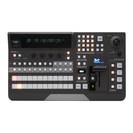
Page 13: Hvs-30Ou (Operation Unit)
Description Refer to Lit red when power or a cooling fan fail. In such a case, power off the system and consult your FOR-A supplier. The indicator is normally unlit. ALARM indicator This indicator works the same as the ALARM indicator located on the front panel of HVS-300HS. - Page 14 TO MU S/No.LABEL DC12V IN Name Description Refer to TO MU Used for HVS-300HS (Main Unit) connection. CONTROL Used for service purposes. Do not use. Used for DC power connection from the supplied AC DC 12V IN adapter. POWER Used for the unit power On/Off...
-
Page 15: Option Slots
2-3. Option Slots All expansion cards can be fitted via the rear of the HVS-300HS panel. The bottom 4 slots (A, B, C and D shown in the figure in this page) are dedicated to these optional cards. IMPORTANT For the details about system expansion (optional cards) and fan replacement, contact your FOR-A supplier. -
Page 16: Interfaces
2-4. Interfaces 2-4-1. EDITOR Connector 9-pin D-sub (male) with inch screws Pin Assignment Table Pin No. Signal Name In/Out Description Frame ground Transmit data (-) Receive data (+) Signal ground Not used Signal ground Transmit data (+) Receive data (-) Frame ground 2-4-2. -
Page 17: Gpi/Tally Out Connector
The pin assignment shown above is the factory default assignment. Pin assignments can be changed via operational menus. GPI IN Circuit Switch or Relay Open corrector External HVS-300HS External HVS-300HS GPI OUT/ TALLY Out Circuit HVS-300HS External Device Max voltage:5V... -
Page 18: Connection
3. Connection 3-1. Basic Connection POWER CONTROL TO MU S/No.LABEL DC12V IN 75-ohm termination AC Adapter TSG (REF signal) VTR, Video Server, etc. PGM 1 PGM 2 AUX 1 AUX 2 REF IN REF OUT TO O U OPTION SLOT AC power source SDI INPUT SDI OUTPUT... -
Page 19: Optional Configuration
3-2. Optional Configuration POWER CONTROL TO MU S/No.LABEL DC12V IN 75-ohm termination AC Adapter TSG (REF signal) Editor GPI Controller VTR, Video Server, etc. ETHERNET PGM 1 PGM 2 AUX 1 AUX 2 REF OUT REF IN TO O U AC power OPTION SLOT SDI INPUT... -
Page 20: Setup
MU (Main Unit) Power supply Supply power to the MU using the power cable provided and turn on the power switch located at the front panel of HVS-300HS. 4-2. System Signal Format Selection at the Initial Use When first switching on your unit, please select a signal format as shown below. - Page 21 ENT/STORE MENU 7/SET UP 8/STILL 9/FILE DIRECT PATT 4/WIPE 5/P in P 6/MATT USB MEMORY ±/EVENT 2/KEYER 3/DSK CLR/TRANS RATE /RECALL ENT/STORE . (DOT) MENU/DIRECT PATT/EVENT/KEY PAD PAGE USER BUTTON ALARM NOR/REV DIRECTION The selected format and aspect are applied after restarting the switcher.
-
Page 22: Menu Operations
5. Menu Operations 5-1. How to Access Menus 5-1-1. Menu Access Buttons The MENU/ DIRECT PATT/ EVENT/ KEY PAD block to the right of the menu display has four modes: Menu Access, Numeric Input, Pattern Selection and Event Control. The current operational mode is displayed at the upper right of the menu display. -
Page 23: Other Menu Access Buttons
2/KEYER 3/DSK SIZE CLR/TRANS RATE /RECALL ENT/STORE . (DOT) MENU/DIRECT PATT/EVENT/KEY PAD USER BUTTON (PUSH to DEF) PAGE USER BUTTON ALARM HVS-300HS NOR/REV DIRECTION DIGITAL VIDEO SWITCHER TRANS PREV KEYER BKGD KEYER KEYER PREV CLEAN P IN P NEXT TRANSITION... -
Page 24: How To Set Values
5-2. How to Set Values 5-2-1. Displaying Parameters To display the desired menu, press the MENU button (The MENU button will light up.), then press the related menu button in the Keypad block. (See section 5-1. "How to Access Menus.") If a menu has multiple submenus such as the SETUP menu, navigate to submenus following the procedure below. -
Page 25: Changing Settings Or Values By Using F1 To F4
Page Navigation As shown in the example below, the [SETUP-INPUT-PROC AMP] submenu spreads across three pages. When first accessed, page 1 of 3 will be displayed. To go to page 2, simply press the PAGE DOWN button. Pressing the PAGE UP button returns you to page 1. Pressing the PAGE UP button when located at the first page brings you up one level in the menus. -
Page 26: Changing Settings Or Values By Using The Numeric Keypad
(PUSH to DEF) PAGE USER BUTTON ALARM HVS-300HS DIGITAL VIDEO SWITCHER IMPORTANT When pressing a push-button, press it down lightly and release it within 1 sec. Note that if you press and hold a control button for more than 1 sec., related setting will be returned to their default value and a beep will be heard. -
Page 27: Changing Settings Or Values By Using The Joystick
5-2-4. Changing Settings or Values by Using the Joystick Users can also use the joystick and the SIZE control in the JOYSTICK block for making position, size and color settings to specific parameters. The parameters controllable from the JOYSTICK block are shown in the table below. Controllable Parameters Parameter Menu... -
Page 28: How To Return Settings To Default
5-3. How to Return Settings to Default 5-3-1. Returning Parameter to Default Pressing and holding down Control Push-buttons Press and hold the control push-button (F1 - F4) below each parameter to return their settings to factory default. Briefly pressing the SIZE control If you need to reset parameters controllable from the JOYSTICK block to factory default, display parameters and briefly press the SIZE control. -
Page 29: User Button
/RECALL ENT/STORE . (DOT) MENU/DIRECT PATT/EVENT/KEY PAD USER BUTTON (PUSH to DEF) PAGE OU1, OU2 USER BUTTON ALARM HVS-300HS DIGITAL VIDEO SWITCHER 6-1. Setting USER Buttons USER Button Default Assignments Button Default Setting GPI IN ENABLE EDITOR ENABLE NONE NONE... - Page 30 SET UP SYSTEM-FORMAT MENU SET UP EDITOR MENU SET UP MV MENU SET UP STATUS MENU KEYER KEYER EDGE KEYER KEYER AUTO CK KEYER KEYER MATT KEYER KEYER GAIN/CLIP KEYER KEYER POS/SIZE KEYER KEYER CROP KEYER KEYER BORDER KEYER KEYER SUB EFF DSK EDGE DSK MATT DSK GAIN/CLIP...
- Page 31 When USTRS (User Transition) was selected for the TYPE item: Setting Function Button Indication KEYER SCALER KEYER MIX KEYER SLIDE LEFT On-Air: Lit orange, Performs the user transition for KEYER. KEYER SLIDE RIGHT Off-Air: Unlit KEYER SLIDE TOP KEYER SLIDE BOTTOM DSK SCALER DSK MIX DSK SLIDE LEFT...
-
Page 32: Video Sources
7. Video Sources 7-1. How to Give Name to Sources Signals available for selection on the PGM/PST bus and the KEY/AUX bus can be assigned user specific names, to make them easier to identify for operators. User names can be given to input signals, internally generated black matt and matt signals, and still pictures. -
Page 33: How To Assign Sources To Bus Buttons
7-2. How to Assign Sources to Bus buttons Primary and optional video inputs, internally generated signals (black, mattes etc) and captured stills can be freely be assigned to any PGM/PST or KEY/AUX bus buttons using the procedure below. (1) Press the MENU button and then press the 7/SETUP button to display the SETUP menu’s top page. -
Page 34: Resize Function
7-3. Resize Function A resize function is provided for every input (including optional inputs). This allows users to input SD signals at the same frame-rate as HD mode and use them as HD images by upsizing. To use the Resize function, proceed as follows. (1) Press the MENU button and then press the 7/SETUP button to display the SETUP menu’s top page. -
Page 35: Bus Matte
7-5. Bus Matte One matte signal can be assigned to the PGM/PST and KEY/AUX bus buttons. The matte signals can be assigned to any bus button (Default assignment: Button 12). Refer to section 7-2. "How to Assign Sources to Bus buttons" for the matte assignment. 7-5-1. -
Page 36: Video Outputs
8. Video Outputs 8-1. How to Select Aux signals The AUX1 to AUX3 output signals can be selected from all bus sources (IN01-12, Still1-2, Matte and etc.), program, preview, clean and key out signals. There are two procedures to select signals for auxiliary outputs: via bus buttons or from menu selection. -
Page 37: Preview Set Up
Press and hold down the TRANS PREV button on the left next to the fader lever. Press AUTO or move the fader lever while holding down TRANS PREV. The next transition will be displayed on the PREVIEW output. To exit the transition preview, complete the transition. NOR/REV HVS-300HS DIRECTION DIGITAL VIDEO SWITCHER TRANS PREV KEYER... -
Page 38: Setting Up Preview Image
8-2-2. Setting Up Preview Image (1) Open the [SETUP – OUTPUT-CLEAN/PREVIEW] menu. OUTPUT : CLEAN : PREVIEW OUT : 1/1 CLN/PVW : =OFF :K=OFF D=OFF PP=ON (2) Turn F2, F3 and F4 to set whether the KEYER, DSK and PinP images are to be displayed on the preview image. -
Page 39: Setting Up And Outputting Key Out
8-4. Setting Up and Outputting KEY OUT The KEY OUT signal (switcher processed key cut signal) can be assigned to AUX outputs. Several kinds of key signals can be used as KEY OUT, such as KEYER and DSK mixed key signal and DVE key signal. - Page 40 (4) Select the signal format and aspect ratio. Available selections are shown in the tables below. If HVS-30HSDO is installed: System format Channel FORMAT setting ASPECT setting HDSDI (Fixed) ----- HDSDI (Fixed) ----- 1080i/59.94, 60, 50, 720p/59.94, 60, 50 SDSDI 4:3, SQUEEZE, LETTER Ch1, Ch2 If HVS-30HSAO is installed:...
-
Page 41: Pgm/Pst Bus Operation
9. PGM/PST Bus Operation 9-1. PGM/PST Bus buttons At factory default, video inputs, Stills and Matt are assigned to the PGM/PST bus buttons. To Select Video in PGM Press the desired bus button on the PGM bus. The video signal assigned to the selected bus button is displayed on the program output screen. -
Page 42: Setting-Up And Using The Shift Function
9-3. Setting-up and Using the SHIFT function In PGM/PST and KEY/AUX, users can select a video signal from 12 sources, because each bus row has 12 bus buttons. On this control panel the SHIFT function can also be assigned to a bus button in the same way video sources can. -
Page 43: Transition Operations
10. Transition Operations The following transition-related operations are possible. BLACK transition Background CUT, MIX, Pattern transitions DSK CUT, MIX and SLIDE IN/OUT and SCALER. KEYER CUT, MIX, SLIDE IN/OUT, SCALER and Pattern transitions Transitions setup by next transition bus selection (BKGD and KEYER) Transitions using the AUTO button or the fader lever On-Air indicators for KEYER, DSK and PinP1/2. -
Page 44: Available Transitions
10-2. Available Transitions Fader Wipe Transition Rate Transition Execute Button or Type Limit Direction Setting Tool Setting setting BLACK Available BLACK TRANS button - - DSK AUTO button - - - (Advanced Transition mode) Available - - DSK AUTO button USER Available ON AIR (DSK) button... -
Page 45: Dsk Transitions
10-4. DSK Transitions (1) Setup a DSK key. (See section 12. "KEYER and DSK.") (2) Perform DSK transition as described below. NOR/REV DIRECTION KEYER BKGD KEYER NEXT TRANSITION P IN P PATTERN/RATE FADER LIMIT P IN P WIPE TRANSITION TYPE AUTO ON AIR To perform CUT transition:... - Page 46 NOR/REV DIRECTION KEYER BKGD KEYER NEXT TRANSITION P IN P PATTERN/RATE FADER LIMIT P IN P WIPE TRANSITION TYPE AUTO ON AIR KEYER AUTO button The KEYER AUTO button can works in different ways (CUT or AUTO), depending on the menu setting.
-
Page 47: Background Transitions
10-6. Background Transitions CUT Transition (1) Select a video source in the PST bus block. (2) Press the BKGD button in the NEXT TRANSITION block. (3) Press CUT to perform the background CUT transition. MIX Transition (1) Select a video source in the PST bus block. (2) Press the BKGD button in the NEXT TRANSITION block. -
Page 48: Pattern (Wipe) Transitions
10-7. Pattern (WIPE) Transitions Patterns are available on background and KEYER transitions. This section explains how to perform pattern transitions, using a background transition as an illustration. (1) Select a background video source on the PGM/PST bus. The bus button ligthts up red to indicate that the video is on-air and the button lights up orange to indicate that the video is set up for the next transition. -
Page 49: Advanced Settings For Transitions
10-8. Advanced Settings for Transitions 10-8-1. Fader Limit The fader limit setting determines how far your transition can proceed electrically. When performing transitions (mix or other) there may be times when you want the transition to the next signal to only complete to a certain degree instead of fully switching from one picture to another. -
Page 50: Transition Rate
10-8-2. Transition Rate The transition rate setting determines how long transitions takes in frames to electrically complete. (1) Press the CLR/TRANS RATE button in the MENU/DIRECT PATT/EVENT/KEYPAD block to display the TRANS menu. MENU 7/SET UP 8/STILL 9/FILE DIRECT PATT 4/WIPE 5/P in P 6/MATT... -
Page 51: User Transitions
10-8-3. User Transitions A specific transition effect such as Scale Up/Down or Slide In/Out can be set to each ON AIR button for KEYER, DSK, PinP1 and PinP2. Once a transition effect is set for the ON AIR button, the effect transition can be executed by simply pressing ON AIR. To apply the transition effect to ON AIR buttons, proceed as follows. -
Page 52: How To Select Patterns
10-9. How to Select Patterns Wipe patterns are available for background and KEYER transitions. More than 150 preset patterns are provided. This chapter explains how to select patterns for the transition, how to check which pattern is currently selected and how to select patterns quickly using the Direct Pattern function. - Page 53 When switching to DIRECT PATT mode, the number buttons onto which patterns are already saved light up. If a user presses one of them to save a selected pattern, the number button blinks. To overwrite the pattern, press the number button again. If users cannot overwrite the number buttons, change the OVER WR (overwrite) item from DISBL (disabled) to ON in the [DIRECT RECALL] menu.
-
Page 54: Wipe Pattern Modify
11. WIPE Pattern Modify 11-1. Preset Pattern Groups The WIPE preset patterns (No.0-202) can be changed or modified from their original patterns. Basically the preset patterns are categorized into four different groups. The available items in the WIPE modify menu are also different according to the type of groups Pattern No. -
Page 55: Pattern Modify Example1 (Pattern 20)
11-3. Pattern Modify Example1 (Pattern 20) This modification example adds a border effect to the KEYER transition using Pattern 20. (1) Set up KEYER (See section 12. "KEYER and DSK.") (2) Press KEYER in the NEXT TRANSITION block. (3) Press WIPE in the TRNSITION TYPE block. (4) The [TRANS - BKGD] menu appears in the Menu Display. -
Page 56: Pattern Modify Example1 (Pattern 117)
11-4. Pattern Modify Example1 (Pattern 117) This modification example also adds a border effect using Pattern 117. However Pattern 117 has different border settings than Pattern 20. It can use both inside and outside border effects. (1) Select the signal used for the next transition in the PST bus. (2) Press BKGD in the NEXT TRANSITION block. -
Page 57: Wipe Menu
11-5. WIPE Menu 11-5-1. No.0-99 WIPE :>BORDER >POS/ANGL>MULTI >SUB EFF No.0XX :>INIT WIPE :SIGNAL : WIDTH : SOFT : 1/2 BORDER : =MATT : =0.0 : =0.0 WIPE BORDER COLOR :RECALL : 2/2 BORDER :S=66.3 L=5.4 H=3.5 : >BLUE : WIPE POSITION : ANGLE :ASPECT : 1/1... -
Page 58: No.100-137
11-5-2. No.100-137 WIPE :>BORDER >POS/ASP >CROP >SUB EFF No.1XX :>INIT WIPE INSIDE OUTSIDE : 1/3 BORDER :X=0 :X=0 WIPE INSIDE :OUTSIDE: : 2/3 BDR SOFT:X=0 : =0 WIPE BORDER COLOR :RECALL : 3/3 BDR COL :S=66.3 L=5.4 H=3.5 : >BLUE : WIPE POSITION : SIZE... -
Page 59: No.140-147
11-5-3. No.140-147 WIPE :>BORDER >TURN >CROP >SUB EFF No.1XX :>INIT NO.140 to 147 WIPE INSIDE OUTSIDE : 1/3 BORDER :X=0 :X=0 WIPE INSIDE :OUTSIDE: : 2/3 BDR SOFT:X=0 : =0 WIPE BORDER COLOR :RECALL : 3/3 BDR COL :S=66.3 L=5.4 H=3.5 : >BLUE : WIPE... -
Page 60: No.200
11-5-4. No.200- WIPE :>SUB EFF >INIT No.2XX WIPE :EFFECT : MONO COLOR : 1/3 SUB EFF : =NOR :S=0.0 H=0.0 En=OFF WIPE DEFOCUS PAINT : 2/3 SUB EFF :H=0.0 V=0.0 :Y=0 WIPE :FREEZE :STROBE : NEGA :MOSAIC : 3/3 SUB EFF : =OFF : =OFF : =OFF : =OFF... -
Page 61: Keyer And Dsk
12. KEYER and DSK Using keyers enables you to superimpose titles and images onto background signals. With the HVS-300HS, two keyers are available: KEYER and DSK. KEYER and DSK can use Luminance Key and Bus Key, and KEYER can also use Chroma Key. -
Page 62: Bus Key
Insert signal and a Key Source signal in the menus. Since selecting a signal in the menu takes time, the HVS-300HS has got a KEY LINK function, which enables you to select a key source and insert using a source button only. See sections 12-2-1. “Creating Key Link” and 12-2-1 “Selecting a Signal Using Key Link”... -
Page 63: Selecting A Signal Using Key Link
Pair of Keys 1 Pair of Keys 2 Signal Name Source Button Signal Name Source Button Key Insert IN01 MATT Key Source IN02 IN03 (1) Double-click DSK in BUS SELECT to display the [DSK SETUP] menu. (2) Turn F1 to select INS/SRC, and press F1 or the PAGE DOWN button to display the [DSK - INS/SRC] menu. -
Page 64: Chroma Key
12-3. Chroma Key Chromakey is a method for creating a key signal using a chroma component instead of a luminance component. It is mostly used for compositing moving subjects such a person in the virtual background. For example, to place a person onto a background graphic, first film the person standing in front of a background such as a blue screen. -
Page 65: Chromakey Adjustments
12-3-2. Chromakey adjustments If the desired result is not achieved using the automatic chromakey generation, fine adjustments can be made as follows: Adjusting Edges Used to adjust the edge of the Keyed area when it appears unnatural. Press the PAGE DOWN button to go to PAGE2 of the chromakey menu. Adjust the left edge in the L (LEFT) item and the right edge in the R (RIGHT) item. -
Page 66: Key Matt
12-4. KEY MATT In addition to the bus matt signal, the MATT signal can be used for Keying. Follow the steps below to set the KEY MATT color in the DSK menu (or KEYER menu). (1) Double-click DSK in BUS SELECT to display the [DSK SETUP] menu. (2) Turn F1 to select INS/SRC, and press F1 or the PAGE DOWN button. -
Page 67: Mask And Invert
12-6. Mask and Invert Mask and Invert can be used for keys and DSKs. DSK is taken as an example in this section. 12-6-1. Inverting Keyer and Background Setting Invert to ON inverts the Keyer image and the background image. Set INVERT in the [DSK - INS/SRC] menu to ON. - Page 68 AUX/DSK Mask The selected AUX bus signal is used for mask instead of Box. (1) Create a Key. (2) Double-click DSK (or KEYER) in BUS SELECT to display the DSK (KEYER) menu. (3) Turn F1 to select MASK, and press F1 or the PAGE DOWN button to open the [DSK – MASK] menu.
-
Page 69: Dve Effects On Keys
13. DVE Effects on Keys 2D-DVE effects are available for KEYER and DSK. The 2D-DVE is available by just setting the 2D DVE item to ON in the KEYER or the DSK menu. As an example, this section explains how to add a 2D-DVE effect on the DSK. -
Page 70: Changing Sizes Or Aspect Ratios
13-3. Changing Sizes or Aspect Ratios Changing sizes Sizes (1) Go to the [DSK - POS/SIZE] menu PAGE1. POSITION : SIZE :2D DVE : 1/3 POS/SIZE:X=0 : =500 : =ON (2) Turn F3 to adjust the size of the DSK image. (The figures below are examples of SIZE=500 and SIZE=750. -
Page 71: Fade
13-4. FADE The FADE allows users to add an effect to make backgrounds transparent. (1) Go to the [DSK - POS/SIZE] menu PAGE2. ASPECT : FADE : 2/3 ASPECT :X=1000 Y=1000 : =0.0 (2) Turn F3 to set the FADE level for the DSK image. Increasing the value makes the backgound transparent. -
Page 72: Key Edge
13-6. Key Edge The EDGE function allows users to add border type edges on KEYER and DSK. Two types of edges are available; Normal and Outline. The width, transparency, and color can be set for the edges. Shadow effects can also be added by changing the position of the edges. To do this, please follow the procedures below. -
Page 73: Sub Effect
13-7. SUB EFFECT The SUB EFFECT menu allows users to add MONO COLOR, DEFOCUS, and PAINT COLOR effects. Access the SUB EFFECT menu as shown below. (1) Press the MENU button and then the 3/DSK button to display the [DSK SETUP] menu. (2) Turn F1 to select SUB EFF, then press F1 or the PAGE DOWN button to display the [DSK - SUB EFF] menu. -
Page 74: Freeze, Strobe, Nega, Mosaic
13-7-4. FREEZE, STROBE, NEGA, MOSAIC Freeze, strobe, negative, and mosaic effects are also available. (1) Go to the [DSK - SUB EFF] menu PAGE3. :FREEZE :STROBE : NEGA :MOSAIC : 3/3 FREEZE :=OFF : =OFF : =OFF : =OFF (2) When applying these effects, please refer to the table below. Parameter Description Allows users to set enable the freeze effect function. -
Page 75: Borders
13-8. BORDERS Borders can be added to DSK images. Inside border and outside borders can be adjusted independently. (1) Go to the [DSK - BORDER] menu. (2) To use the inside border, set the width at the INSIDE X and Y. To use the outside border, set the width at the OUTSIDE X and Y. -
Page 76: Still Store
14. Still Store The switcher can capture and memorize up to 2 still pictures from the switcher output video. Captured stills can then be used as signals for key source, key insertion, PGM select, PST select or AUX bus select (See section 7-2. "How to Assign Sources to Bus buttons" for assigning stills.). Although the stored stills are cleared when the switcher is powered down, they can be backed up within the switcher. -
Page 77: Picture-In-Picture
15. Picture-in-Picture The PIP (picture-in-picture) feature allows any video (sub-screens) to be displayed on full screen simultaneously. In the switcher, two sub-screens (PinP1 and PinP2) can be inserted on the background video. The setup for PIP pictures is the same. This section explains how to setup and display PinP pictures as shown in the figure below (as an example). -
Page 78: Position And Size
15-1-3. Position and Size (1) Press twice quickly the PinP1 button in the BUS SELECT to display the PinP1 menu. (2) Press the PAGE DOWN button to go to PAGE4. (3) Turn F3 to make PinP1 a little bit larger. (4) Use F1 and F2 to move PinP1 to the top left-hand side. -
Page 79: Crop And Border
15-1-4. Crop and Border Using the procedure just used for PiP1, Insert PinP2 to the PGM image, move PinP2 to a desired position and change PinP2 size. The example below shows how to crop PinP and add a border. (1) Press twice quickly the PinP1 button in the BUS SELECT to display the PinP1 menu. (2) Press the PAGE DOWN button to go to PAGE4. - Page 80 To Change Functional Behavior of the Transition Buttons (1) Press the CLR/TRANS RATE button in the MENU/DIRECT PATT/EVENT/KEYPAD block to display the TRANS menu. (2) Press the PAGE DOWN button to go to PAGE 3 or PAGE 4. (3) Turn F2 to select a transition effect for the ON-AIR button. Turn F3 to select a transition effect for the PinP AUTO button.
-
Page 81: Multiviewer
16. Multiviewer The multiviewer allows users to monitor multiple images such as the video sources input to the switcher and internally generated or combined images on the same screen. Three types of split displays are available: quad, 10 and 16 way. The video titles and the on-air tally information can be also displayed. -
Page 82: Selecting Video For Each Split Area
16-3. Selecting Video for Each Split Area This section shows how to a video source for each split area in the multiviewer screen. This is done in the [SETUP-OUTPUT-MV SCRN] menu. (1) Quickly press twice the MV button in the BUS SELECT block to display the [SETUP- OUTPUT-MV SCRN] menu. -
Page 83: On-Air Tally
16-4-2. On-air Tally The tally indicates which video is currently On-air (output from the program) and which video is set to be the next output. The multiviewer has two types of tally indicators: Frame and Marker. You can use one at a time or both simultaneously. The Frame indicator is active by default. -
Page 84: Event Memory
17. Event Memory The switcher can save control panel setup statuses as data for recall when needed. This function is called Event Memory. This Event Memory function enables quick recall of the same setting statuses. The keypad is used to save and recall events. Saved event memories can be saved and recalled from USB flash memories. -
Page 85: Recalling Events
Data not saved in the event memory All SETUP menu settings All FILE menu settings STILL images USER TRANS and ADV CTRL settings in the TRANS menu (6) Press a number button (0-9) on the Keypad to store the event. If an Event is Already Saved to a Button: When ENT/STORE is pressed, the light of the buttons (0 to 9) are off if no events are saved. -
Page 86: Overwrite Protection
To Recall Events (in the detailed way): (1) Press the ±/EVENT button at the top right-hand side of the menu display. The [EVENT MEMORY] menu is displayed and the Keypad changed to Event mode. (2) Turn F1 to select an event page in the [EVENT MEMORY] menu. (3) Press the number button where the needed data is stored. -
Page 87: Loading Event At Start-Up
To Delete Data for an Event Page: (1) Press the ±/EVENT button at the top right-hand side of the menu display. The [EVENT MEMORY] menu is displayed. (2) Turn F1 to select an event page to be deleted. (3) Turn F3 to set PAGECLR to CRNT (current), then press F3. The data saved in the event page will then be cleared. -
Page 88: File Operations
3/DSK SIZE CLR/TRANS RATE /RECALL ENT/STORE . (DOT) USER BUTTON MENU/DIRECT PATT/EVENT/KEY PAD (PUSH to DEF) PAGE USER BUTTON ALARM NOR/REV HVS-300HS DIRECTION DIGITAL VIDEO SWITCHER TRANS PREV KEYER BKGD KEYER KEYER PREV CLEAN P IN P NEXT TRANSITION KEY/AUX... -
Page 89: Saving Data To Usb Flash Memory
18-3. Saving Data to USB Flash Memory This section explains how to save the panel settings to the USB memory by using a "data.all" file as an example. (1) Insert the USB flash memory into the USB port. (2) Press the MENU button, then press the 9/FILE button to open the FILE top menu. (3) Turn F1 to select SAVE, and then press F1 or the PAGE DOWN button to open the [FILE-SAVE] menu. -
Page 90: Loading Data From Usb Flash Memory
18-4. Loading Data from USB Flash Memory 18-4-1. To Load Setting Data This section explains how to load setting data to the USB memory by using a "data.all" file as an example. (1) Insert the USB flash memory into the USB port. (2) Press the MENU button, then press the 9/FILE button to open the FILE top menu. -
Page 91: Moving Between Directories In The Usb Flash Memory
18-5. Moving between Directories in the USB Flash Memory The directories in the USB flash memory are displayed after the word "<DIR>", <DIR>JPEG for example, at the upper right-hand in the FILE menu as shown below. Directory name FILE : EXT : LOAD : <DIR>JPEG LOAD... -
Page 92: System Setup Settings
19. System Setup Settings 19-1. Selecting System Signal Format (1) Press the MENU button, then press the 7/SETUP button to display the SETUP top menu. (2) Turn F1 to select SYSTEM, then press F1 or the PAGE DOWN button to open the [SETUP- SYSTEM] menu. -
Page 93: Selecting Reference Signal
19-2. Selecting Reference Signal The switcher provides reference input, its loop-through and output connectors in the GENLOCK section on the rear panel. 19-2-1. To Set Reference Input (1) Press the MENU button, then press the 7/SETUP button to display the SETUP top menu. Turn F1 to select SYSTEM, then press F1 or the PAGE DOWN button to open the [SETUP- SYSTEM] menu. -
Page 94: Adjusting Video Signal Levels
19-3. Adjusting Video Signal Levels 19-3-1. Proc Amp The switcher provides the following Proc Amp features. (1) Press the MENU button, then press the 7/SETUP button to display the SETUP top menu. Turn F1 to select INPUT, then press F1 or the PAGE DOWN button to open the [SETUP- INPUT] menu. -
Page 95: Safety Area Markers
19-4. Safety Area Markers Various markers indicating the safety area, the center of the screen, and the aspect ratio can be displayed on the desired output. (1) Press the MENU button, then press the 7/SETUP button to display the SETUP top menu. Turn F1 to select OUTPUT, then press F1 or the PAGE DOWN button to open the [SETUP- OUTPUT] menu. -
Page 96: Setting Date And Time
19-5. Setting Date and Time (1) Press the MENU button, then press the 7/SETUP button to display the SETUP top menu. Turn F1 to select SYSTEM, then press F1 or the PAGE DOWN button to open the [SETUP- SYSTEM] menu. (2) Turn F1 to select TIME, then press F1 or the PAGE DOWN button to open the [SETUP - SYSTEM - TIME] menu. -
Page 97: Reboot And Initialize
20. Reboot and Initialize 20-1. Rebooting System (1) Press the MENU button, then press the 7/SETUP button to display the SETUP top menu. (2) Turn F1 to select SYSTEM, then press F1 or the PAGE DOWN button to open the [SETUP- SYSTEM] menu. -
Page 98: Setup Setting For Hvs-30Fp And Hvs-30Ru
21. Setup Setting for HVS-30FP and HVS-30RU The signal selection buttons and free functional (USER ) buttons in the HVS-30FP and HVS-30RU can be set in the control panel menu same as the buttons on the control panel do. HVS-30FP and HVS-30RU share the same settings if both units are connected. -
Page 99: Setting User Buttons On Hvs-30Fp And Hvs-30Ru
21-2. Setting USER Buttons on HVS-30FP and HVS-30RU USER Button Default Assignments in HVS-30FP Button Default setting USER1 on HVS-30FP and HVS-30RU AUX XPT SELECT USER2 on HVS-30FP and HVS-30RU PinP XPT SELECT (1) Press the MENU button and then press the 7/SETUP button to display the SETUP menu's top page. -
Page 100: Specifications And Dimensions
22. Specifications and Dimensions 22-1. Specifications 22-1-1. HVS-300HS Video Signal Specifications in HD SDI mode TV Standard 1080/60i, 1080/59.94i, 1080/50i, 1080/24PsF, 1080/23.98PsF, 720/60p, 720/59.94p, 720/50p (Menu-selectable) Signal Processing 4:2:2:4 10-bit Digital component Quantization Y: 10-bit, C: 10-bit, KEY: 10-bit Video Input HD-SDI: 1.485Gbps or 1.485/1.001Gbps or... -
Page 101: Hvs-30Ou
Video Output SD-SDI: 270Mbps, 75Ω, BNC (Option) SD analog component: Y: 1.0Vp-p, R-Y/B-Y: 0.7Vp-p 75Ω BNC Analog composite: 1.0Vp-p, 75Ω, BNC DVI-D: Resolution (SVGA) (HDCP incompatible) RGB: Resolution (SVGA) R/G/B: 0.7Vp-p, H/V: TTL Reference Input BB: NTSC: 0.429Vp-p/PAL: 0.45Vp-p, 75Ω, or loopthrough, 1ea., BNC Reference Output BB: NTSC: 0.429Vp-p/PAL: 0.45Vp-p, 75Ω, 1ea., BNC I/O Delay... -
Page 102: External Dimensions
22-2. External Dimensions 22-2-1. HVS-300HS (All dimensions in mm) HVS-300HS DI G I T AL VI D EO SWI T CHER POW ER ALARM POWER... -
Page 103: Hvs-30Ou
SIZE CLR/TRANS RATE /RECALL ENT/STORE . (DOT ) USER BUTTON MENU/DIRECT PATT/EVENT/KEY PAD (PUSH to DEF) PAGE USER BUTTON ALARM NOR/REV HVS-300HS DIRECTION DIGITAL VIDEO SWITCHER TRANS PREV KEYER KEYER PREV CLEAN BKGD KEYER P IN P NEXT TRANSITION KEY/AUX... -
Page 105: Appendix 1. Available File List
File Name File Data Description pm8440xx.mot HVS-300HS software upgrade data pm8440xx.oum HVS-30OU software upgrade data xxxxxxxx.bin HVS-300HS FPGA firmware upgrade data Available USB flash memory Manufacturer Series Name Model Name (Tested memory) SONY Micro Vault Series USM128J, USM256J, USM2GJ, USM2GH... -
Page 106: Appendix 2. Transition Pattern List
Appendix 2. Transition Pattern List 2-1. WIPE Type... -
Page 107: 2.5D Dve Type
2-2. 2D/2.5D DVE Type 2-3. 3D DVE Type... -
Page 109: Index
Index 2D/2.5D DVE Type......................app-3 3D DVE Type ........................app-3 Adding Titles, On-air Tally and Frame Border.................72 Adjusting Key Signal .......................55 Adjusting Video Signal Levels ....................84 Advanced Auto Transitions .....................41 Advanced Settings for Transitions...................39 Assigning Sources to Bus buttons...................88 Assigning the Multiviewer function to an AUX Bus..............72 Available File List .......................app-1 Available Files .........................78 Available Transitions .......................34... - Page 110 How to Select Aux signals ...................... 26 How to Select Patterns ......................42 How to Set Values ........................14 HVS-300HS (Dimensions) ...................... 92 HVS-300HS (Main Unit) ......................2 HVS-300HS (Specifications) ....................90 HVS-30FP and HVS-30RU..................... 88 HVS-30OU (Dimensions) ....................... 93 HVS-30OU (Operation Unit) .....................
- Page 111 Menu Access Buttons ......................12 Menu Operations........................12 MONO COLOR (KEYER and DVE) ..................63 Moving between Directories in the USB Flash Memory ............81 Multiviewer ..........................71 On-air Tally (Multiviewer) ......................73 Option Slots ..........................5 Optional Configuration ......................9 Other Menu Access Buttons ....................13 Outputting Clean Image ......................28 Overwrite Protection (Event) ....................76 PAINT COLOR (KEYER and DVE) ..................63 Panel Descriptions ........................2...
- Page 112 Selecting Video in KEY/AUX ....................26 Selecting Video in the Menu ....................26 Setting Up and Outputting KEY OUT..................29 Setting Up Optional Outputs ....................29 Setting Up Preview Image ...................... 28 Setting Up the Matte Color ..................... 25 Setting USER Buttons ......................19 Setting USER Buttons on HVS-30FP and HVS-30RU............
- Page 113 Warning This equipment has been tested and found to comply with the limits for a Class A digital device, pursuant to Part 15 of FCC Rules. These limits are designed to provide reasonable protection against harmful interference when the equipment is operated in a commercial environment. This equipment generates, uses, and can radiate radio frequency energy and, if not installed and used in accordance with the instruction manual, may cause harmful interference to radio communications.
- Page 114 Two Executive Drive, Suite 670, Fort Lee Executive Park, Fort Lee NJ 07024, USA Phone : +1 (201) 944-1120 Fax : +1 (201) 944-1132 FOR-A America Distribution & Service Center 2400 N.E. Waldo Road, Gainesville, FL 32609, USA Phone: +1 352-371-1505 Fax: +1 352-378-5320...
Need help?
Do you have a question about the HVS-300HS and is the answer not in the manual?
Questions and answers