
Related Manuals for FOR-A HVS-300HS


Summary of Contents for FOR-A HVS-300HS
- Page 1 OPERATION MANUAL HVS-300HS HVS-300RPS Digital Video Switcher HVS-30OU Operation Unit Edition - Rev. 8...
- Page 2 Edition Revision History Edit. Rev. Date Description Section, page Preliminary 2009/02/13 2009/02/27 2009/03/10 "How to back up settings" "OSD operation" added 21-3 Factual errors corrected 2009/04/30 Max. voltage for GPI OUT circuit changed to 40V 2-4-3 "Setting Up Additional Inputs" added. "Setting Up Additional Outputs"...
- Page 3 Precautions Important Safety Warnings [Power] Operate unit only on the specified supply voltage. Caution Disconnect power cord by connector only. Do not pull on cable portion. Do not place or drop heavy or sharp-edged objects on power cord. A damaged cord can cause fire or electrical shock hazards.
- Page 4 [Transportation] Handle with care to avoid shocks in transit. Shocks may cause malfunction. When you need to transport the unit, use the original packing materials or alternate adequate packing. Caution [Circuitry Access] Do not remove covers, panels, casing, or access circuitry with power applied to the unit! Turn power off and disconnect power cord prior to removal.
- Page 5 * Up to two input cards of HVS-30HSDI/HSAI/PCIN can be installed. * Up to two output cards of HVS-30HSDO/HSAO/PCO can be installed. * Both HVS-300HS and HVS-300RPS can install the same type and the same number of option cards. HVS-30OU Box...
-
Page 6: Rack Mounting
Other Option ITEM REMARKS HVS-AUX8 AUX remote panel (Hanabi Series Option) HVS-AUX16 AUX remote panel (Hanabi Series Option) HVS-AUX8RK, Remote Kit for Aux bus Control Box HVS-AUXRK (Hanabi Series Option) Tally Relay Output unit (20/32-output) HVS-TALR20/32 (*1) (Hanabi Series Option) HVS-TALOC20/32 Tally Open Collector Output unit (20/32-output) (*1) -
Page 7: Table Of Contents
1-1. Welcome ..........................1 1-2. Features ..........................1 1-3. About This Manual ......................1 2. Panel Descriptions ........................2 2-1. HVS-300HS (Standard Model) ................... 2 2-2. HVS-300RPS (Power Redundant Model) ................3 2-3. HVS-30OU (Operation Unit)....................4 2-4. Option Slots ........................6 2-5. - Page 8 7-1. How to Select Aux signals ....................31 7-1-1. Selecting Video via Bus Buttons ................31 7-1-2. Selecting Video from Menu Selection ............... 31 7-2. Preview Set Up ........................ 32 7-2-1. Preview bus monitoring .................... 32 7-2-2. Setting Up Preview Image ..................33 7-3.
- Page 9 11-5-1. Creating a Chroma Key ..................60 11-5-2. Chromakey adjustments ..................61 11-6. Mask and Invert ......................63 11-6-1. Inverting Keyer and Background ................63 11-6-2. Key Masks ......................63 11-7. Key Edge ........................64 12. DVE Effects on Keys ......................65 12-1.
- Page 10 17-2. Available Files ....................... 83 17-3. Saving Data to USB Flash Memory ................84 17-4. Loading Data from USB Flash Memory ................. 85 17-4-1. To Load Setting Data ..................... 85 17-4-2. To Download Image Files ..................85 17-5. Moving between Directories in the USB Flash Memory ..........86 17-6.
- Page 11 23-2. Setting USER Buttons on HVS-30FP and HVS-30RU ..........111 23-3. OSD Operation ......................111 24. Specifications and Dimensions ................... 112 24-1. Specifications ....................... 112 24-1-1. HVS-300HS / HVS-300RPS / HVS-30OU / HVS-30RU ........112 24-2. External Dimensions ....................114 24-2-1. HVS-300HS ......................114 24-2-2. HVS-300RPS ......................115 24-2-3.
-
Page 13: Prior To Starting
FOR-A provides a wide range of products, from basic support units to complex system controllers, which have been increasingly joined by products for computer video based systems. Whatever your needs, talk to your FOR-A representative. We will do our best to be of continuing service to you. -
Page 14: Panel Descriptions
Unlit Power is supplied to the unit. Lit red when a cooling fan fails. In such a case, power off the unit and consult your FOR-A supplier. The indicator is normally unlit. ALARM indicator This indicator works the same as the ALARM indicator located on the Control panel. -
Page 15: Front Panel
Unlit Power is supplied to the unit. Lit red when a power or a cooling fan fails. In such a case, power off the unit and consult your FOR-A supplier. The indicator is normally ALARM unlit. indicator * This indicator works the same as the ALARM indicator located on the Control panel. -
Page 16: Control Panel
-Power and fan alarm is indicated for HVS-300RPS. The indicator blinks red when an alarm occurs. In such ALARM indicator a case, power off the system and consult your FOR-A supplier. The indicator is normally unlit. This indicator works the same as the ALARM indicator located on the front panel of the main unit. - Page 17 Rear Panel POWER CONTROL TO MU S/No.LABEL DC12V IN Name Description Refer to Arcnet port. Used for the main unit connection. The other connector (loopthrough) can be used for AUX TO MU 20-4-1 unit connection. The loopthrough connector must be 75 ohm terminated if it is not connected to other system equipment.
-
Page 18: Option Slots
Two output expansion cards can be installed in slot C and D. Two tally relay expansion cards (HVS-30TALR) can be installed in slot A to D. The figure below is an example of HVS-300HS. The option slots of the HVS-300RPS are the same as those of the HVS-300HS. -
Page 19: Interfaces
2-5. Interfaces 2-5-1. EDITOR Connector 9-pin D-sub (male) with inch screws Pin Assignment Table Pin No. Signal Name In/Out Description Frame ground Transmit data (-) Receive data (+) Signal ground Not used Signal ground Transmit data (+) Receive data (-) Frame ground 2-5-2. -
Page 20: Gpi In/Tally Out Connector
The pin assignment shown above is the factory default assignment. Pin assignments can be changed via operational menus. See section 20-1and 0. GPI IN Circuit Switch or Relay Open collector External HVS-300HS External HVS-300HS GPI OUT/ TALLY Out Circuit HVS-300HS External Device... -
Page 21: Tally Out Connector (Hvs-30Talr)
2-5-4. TALLY OUT Connector (HVS-30TALR) The TALLY OUT connectors are available only when HVS-30TALR cards are installed. Pin Assignment Table (37-pin D-sub, female, with inch screws) Channel Channel Pin No. Output signal Pin No. Output signal TALLY OUT1 Normally Open TALLY OUT10 Normally Open TALLY OUT1 COMMON TALLY OUT10 COMMON... - Page 22 TALLY OUT circuit (Relay output) TALLY OUT HVS-30TALR side External device connector COM. VCC = 24VDC = 400 mA (max) RELAY The maximum switching current for each output is 400mA. The HVS-30TALR is a relay board. Use the supplied or commercially-prepared 37-pin D-sub male connector (with #40-40 inch screws) for making a connection cable.
-
Page 23: Connection And Setup
3. Connection and Setup 3-1. Basic Connection POWER CONTROL TO MU S/No.LABEL DC12V IN 75-ohm termination AC Adapter TSG (REF signal) VTR, Video Server, etc. PGM 1 PGM 2 AUX 1 AUX 2 REF IN REF OUT TO O U OPTION SLOT AC power source SDI INPUT... -
Page 24: Optional Configuration
3-2. Optional Configuration POWER CONTROL TO MU S/No.LABEL DC12V IN 75-ohm termination AC Adapter TSG (REF signal) Editor GPI Controller VTR, Video Server, etc. ETHERNET PGM 1 PGM 2 AUX 1 AUX 2 REF OUT REF IN TO O U AC power OPTION SLOT SDI INPUT... -
Page 25: Power On
NOTE See section 15. "Multiviewer" for multi-display connection and setup. See section 20-1. "GPI Control" and section 20-2-2. "Tally Output Settings (GPI IN/TALLY OUT)" for setting up GPI input, GPI output and tally output. See section 20-2-3. "Sending Tally Signals to Tally Units" and 20-2-5. "Connection Settings with Tally Units (RS-422 port setting)", if you configure the tally units (Hanabi series option). - Page 26 SYSTEM FORMAT :ASPECT :SW TMNG: 1/1 FORMAT : =1080/59.94i : =16:9 : =ANY PAGE (6) Press the PAGE UP button to return to the [SETUP - SYSTEM] menu. (7) Turn F1 to select REBOOT. Press ENT/STORE in the Keypad block to reboot the switcher. SETUP :>FORMAT >REF I/O >ARCNET...
-
Page 27: Menu Operations
4. Menu Operations 4-1. How to Access Menus 4-1-1. Menu Access Buttons Press the MENU button below, which changes the buttons in the Keypad block to the menu buttons, and then press the buttons on the Keypad to access menus. MENU button MENU 7/SET UP... -
Page 28: Other Menu Access Buttons
3/DSK SIZE CLR/TRANS RATE /RECALL ENT/STORE . (DOT) MENU/DIRECT PATT/EVENT/KEY PAD USER BUTTON (PUSH to DEF) PAGE USER BUTTON ALARM NOR/REV HVS-300HS DIRECTION DIGITAL VIDEO SWITCHER TRANS PREV KEYER BKGD KEYER KEYER PREV CLEAN P IN P NEXT TRANSITION KEY/AUX... -
Page 29: How To Set Values
4-2. How to Set Values 4-2-1. Displaying Parameters To display the desired menu, press the MENU button (The MENU button will light up.), then press the related menu button in the Keypad block. (See section 4-1. "How to Access Menus.") If a menu has multiple submenus such as the SETUP menu, navigate to submenus following the procedure below. -
Page 30: Changing Settings Or Values By Using F1 To F4
Page Navigation As shown in the example below, the [SETUP-INPUT-PROC AMP] submenu spreads across three pages. When first accessed, page 1 of 3 will be displayed. To go to page 2, simply press the PAGE DOWN button. Pressing the PAGE UP button returns you to page 1. Pressing the PAGE UP button when located at the first page brings you up one level in the menus. -
Page 31: Changing Settings Or Values By Using The Numeric Keypad
(PUSH to DEF) PAGE USER BUTTON ALARM HVS-300HS DIGITAL VIDEO SWITCHER IMPORTANT When pressing a push-button, press it down lightly and release it within 1 sec. Note that if you press and hold a control button for more than 1 sec., related setting will be returned to their default value and a beep will be heard. -
Page 32: Changing Settings Or Values By Using The Joystick
4-2-4. Changing Settings or Values by Using the Joystick Users can also use the joystick and the SIZE control in the JOYSTICK block for making position, size and color settings to specific parameters. The parameters controllable from the JOYSTICK block are shown in the table below. ... -
Page 33: How To Return Settings To Default
4-3. How to Return Settings to Default 4-3-1. Returning Parameter to Default Pressing and holding down Control Push-buttons Press and hold the control push-button (F1 - F4) below each parameter to return their settings to factory default. Pressing and holding down the SIZE control If you need to reset parameters controllable from the JOYSTICK block to factory default, display parameters and then press and hold down the SIZE control. -
Page 34: User Button
User Buttons . (DOT) MENU/DIRECT PATT/EVENT/KEY PAD USER BUTTON (PUSH to DEF) PAGE OU1, OU2 USER BUTTON ALARM HVS-300HS DIGITAL VIDEO SWITCHER 5-1. Setting USER Buttons USER Button Default Assignments Button Default Setting GPI IN ENABLE EDITOR ENABLE NONE... - Page 35 SET UP EDITOR MENU SET UP MV MENU SET UP STATUS MENU KEYER KEYER EDGE KEYER KEYER AUTO CK KEYER KEYER MATT KEYER KEYER GAIN/CLIP KEYER KEYER POS/SIZE KEYER KEYER CROP KEYER KEYER BORDER KEYER KEYER SUB EFF DSK EDGE DSK MATT DSK GAIN/CLIP DSK POS/SIZE...
- Page 36 When USTRS (User Transition) was selected for the TYPE item: Setting Function Button Indication KEYER SCALER KEYER MIX KEYER SLIDE LEFT On-Air: Lit orange, Performs the user transition for KEYER. Off-Air: Unlit KEYER SLIDE RIGHT KEYER SLIDE TOP KEYER SLIDE BOTTOM DSK SCALER DSK MIX DSK SLIDE LEFT...
-
Page 37: Video Sources
6. Video Sources 6-1. How to Give Name to Sources Signals available for selection on the PGM/PST bus and the KEY/AUX bus can be assigned user specific names, to make them easier to identify for operators. User names can be given to input signals, internally generated black matt and matt signals, and still pictures. -
Page 38: How To Assign Sources To Bus Buttons
6-2. How to Assign Sources to Bus buttons Primary and optional video inputs, internally generated signals (black, mattes etc) and captured stills can be freely be assigned to any PGM/PST or KEY/AUX bus buttons using the procedure below. (1) Press the MENU button and then press the 7/SETUP button to display the SETUP menu’s top page. -
Page 39: Resize Function
6-3. Resize Function A resize function is provided for every input including optional inputs, except HVS-30HSDI-A. This allows users to input SD signals at the same frame-rate as HD mode and use them as HD images by upsizing. To use the Resize function, proceed as follows. (1) Press the MENU button and then press the 7/SETUP button to display the SETUP menu’s top page. -
Page 40: Frame Synchronizer
IMPORTANT The Resize function is automatically enabled when SD signals are input to the switcher in HD mode, and FORMAT in the [SYSTEM-INPUT- SIGNAL] menu is set to SDSDI. ((Please make sure the Resize function stays disabled if HDSDI is set for FORMAT.) 6-4. -
Page 41: Setting Up Additional Inputs
6-6. Setting Up Additional Inputs Up to 2 cards of additional inputs can be installed into Slot A and Slot B. PGM 1 PGM 2 AUX 1 AUX 2 REF IN REF OUT TO O U OPTION SLOT SDI INPUT SDI OUTPUT GPI IN/TALLY OUT RS-422... - Page 42 HVS-30HSAI available format System Component Component Composite Component standard Component SMPTE BetaCam 1080/59.94i 1080/29.97PsF Available Available* Available Available* - 720/59.94i 1080/50i, 1080/25PsF Available Available - - Available 720/50p 525/60 Available* Available Available* - - 625/50 Available Available - - -...
-
Page 43: Video Outputs
7. Video Outputs 7-1. How to Select Aux signals The AUX1 to AUX3 output signals can be selected from all bus sources (IN01-12, Still1-2, Matte and etc.), program, preview, clean and key out signals. There are two procedures to select signals for auxiliary outputs: via bus buttons or from menu selection. -
Page 44: Preview Set Up
Press and hold down the TRANS PREV button on the left next to the fader lever. Press AUTO or move the fader lever while holding down TRANS PREV. The next transition will be displayed on the PREVIEW output. To exit the transition preview, complete the transition. NOR/REV HVS-300HS DIRECTION DIGITAL VIDEO SWITCHER TRANS PREV KEYER... -
Page 45: Setting Up Preview Image
7-2-2. Setting Up Preview Image (1) Open the [SETUP – OUTPUT-CLEAN/PREVIEW] (2/2) menu. OUTPUT : KEYER : PinP1 : PinP2 : DSK : 2/2 PREV OUT: =OFF =OFF =OFF (2) Turn F1 to F4 to set whether the KEYER, DSK and PinP images are to be displayed on the preview image. -
Page 46: Setting Up And Outputting Key Out
Item Setting Description KEYER image is added to Clean KEYER KEYER image is not added to Clean. PinP1 or PinP2 image is added to Clean PinP1/2 PinP1 or PinP2 image is not added to Clean. 7-4. Setting Up and Outputting KEY OUT The KEY OUT signal (switcher processed key cut signal) can be assigned to AUX outputs. - Page 47 (1) Open the [SETUP – OUTPUT-OPTION] menu. (2) Turn F1 to select an output channel. C-Ch1 and C-Ch2 is for Slot C and D-Ch1 and D-Ch2 is for Slot D. (3) Turn F1 to select an image to be output from PGM, PREV, CLN, AUX1-AUX3 and MV. OUTPUT :SELECT :OUTPUT :FORMAT :ASPECT : 1/2 OPTION...
-
Page 48: Pgm/Pst Bus Operation
8. PGM/PST Bus Operation 8-1. PGM/PST Bus buttons At factory default, video inputs, Stills and Matt are assigned to the PGM/PST bus buttons. To Select Video in PGM Press the desired bus button on the PGM bus. The video signal assigned to the selected bus button is displayed on the program output screen. -
Page 49: Setting-Up And Using The Shift Function
8-3. Setting-up and Using the SHIFT function In PGM/PST and KEY/AUX, users can select a video signal from 12 sources, because each bus row has 12 bus buttons. On this control panel the SHIFT function can also be assigned to a bus button in the same way video sources can. -
Page 50: Transition Operations
9. Transition Operations The following transition-related operations are possible. BLACK transition Background CUT, MIX, Pattern transitions DSK CUT, MIX and SLIDE IN/OUT and SCALER. KEYER CUT, MIX, SLIDE IN/OUT, SCALER and Pattern transitions Transitions setup by next transition bus selection (BKGD and KEYER) ... -
Page 51: Available Transitions
9-2. Available Transitions Fader Wipe Transition Rate Transition Execute Button or Type Limit Direction Setting Tool Setting setting BLACK Available BLACK TRANS button - - DSK AUTO button - - - (Advanced Transition mode) Available DSK AUTO button - - USER Available ON AIR (DSK) button... -
Page 52: Dsk Transitions
9-4. DSK Transitions (1) Setup a DSK key. (See section 11. "KEYER and DSK.") (2) Perform DSK transition as described below. NOR/REV DIRECTION KEYER BKGD KEYER NEXT TRANSITION P IN P PATTERN/RATE FADER LIMIT P IN P WIPE TRANSITION TYPE AUTO ON AIR To perform CUT transition:... - Page 53 NOR/REV DIRECTION KEYER BKGD KEYER NEXT TRANSITION P IN P PATTERN/RATE FADER LIMIT P IN P WIPE TRANSITION TYPE AUTO ON AIR KEYER AUTO button The KEYER AUTO button can works in different ways (CUT or AUTO), depending on the menu setting.
-
Page 54: Background Transitions
9-6. Background Transitions CUT Transition (1) Select a video source in the PST bus block. (2) Press the BKGD button in the NEXT TRANSITION block. (3) Press CUT to perform the background CUT transition. MIX Transition (1) Select a video source in the PST bus block. (2) Press the BKGD button in the NEXT TRANSITION block. -
Page 55: Pattern (Wipe) Transitions
9-7. Pattern (WIPE) Transitions Patterns are available on background and KEYER transitions. This section explains how to perform pattern transitions, using a background transition as an illustration. (1) Select a background video source on the PGM/PST bus. The bus button ligthts up red to indicate that the video is on-air and the button lights up orange to indicate that the video is set up for the next transition. -
Page 56: Advanced Settings For Transitions
9-8. Advanced Settings for Transitions 9-8-1. Fader Limit The fader limit setting determines how far your transition can proceed electrically. When performing transitions (mix or other) there may be times when you want the transition to the next signal to only complete to a certain degree instead of fully switching from one picture to another. -
Page 57: Transition Rate
9-8-2. Transition Rate The transition rate setting determines how long transitions takes in frames to electrically complete. (1) Press the CLR/TRANS RATE button in the MENU/DIRECT PATT/EVENT/KEYPAD block to display the TRANS menu. MENU 7/SET UP 8/STILL 9/FILE DIRECT PATT 4/WIPE 5/P in P 6/MATT... -
Page 58: User Transitions
9-8-3. User Transitions A specific transition effect such as Scale Up/Down or Slide In/Out can be set to each ON AIR button for KEYER, DSK, PinP1 and PinP2. Once a transition effect is set for the ON AIR button, the effect transition can be executed by simply pressing ON AIR. To apply the transition effect to ON AIR buttons, proceed as follows. -
Page 59: Advanced Auto Transitions
SIZE USER BUTTON (PUSH to DEF) To Change the AUTO button function: (1) Open the TRANS menu. HVS-300HS (2) Press the PAGE DOWN button to go to the DIGITAL VIDEO SWITCHER desired page. KEYER (3) Turn F4 to select a function for the button under the ADV CTL item. -
Page 60: How To Select Patterns
9-9. How to Select Patterns Wipe patterns are available for background and KEYER transitions. More than 150 preset patterns are provided. This chapter explains how to select patterns for the transition, how to check which pattern is currently selected and how to select patterns quickly using the Direct Pattern function. - Page 61 When switching to DIRECT PATT mode, the number buttons onto which patterns are already saved light up. If a user presses one of them to save a selected pattern, the number button blinks. To overwrite the pattern, press the number button again. If users cannot overwrite the number buttons, change the OVER Wr (overwrite) item from DISBL (disabled) to ENABL (enable) in the [DIRECT RECALL] menu.
-
Page 62: Wipe Pattern Modify
10. WIPE Pattern Modify 10-1. Preset Pattern Groups The WIPE preset patterns (No.0-202) can be changed or modified from their original patterns. Basically the preset patterns are categorized into four different groups. The available items in the WIPE modify menu are also different according to the type of groups Pattern No. -
Page 63: Pattern Modify Example1 (Pattern 20)
10-3. Pattern Modify Example1 (Pattern 20) This modification example adds a border effect to the background transition using Pattern 20. (1) Select the signal used for the next transition in the PST bus. (2) Press BKGD in the NEXT TRANSITION block. (3) Press WIPE in the TRNSITION TYPE block. -
Page 64: Pattern Modify Example2 (Pattern 117)
10-4. Pattern Modify Example2 (Pattern 117) This modification example also adds a border effect using Pattern 117. However Pattern 117 has different border settings than Pattern 20. It can use both inside and outside border effects. (1) Set up KEYER (See section 11. "KEYER and DSK.") (2) Press KEYER in the NEXT TRANSITION block. -
Page 65: Wipe Menu
10-5. WIPE Menu 10-5-1. No.0-99 WIPE :>BORDER >POS/ANGL>MULTI >SUB EFF No.0XX :>INIT WIPE :SIGNAL : WIDTH : SOFT : 1/2 BORDER : =MATT : =0.0 : =0.0 WIPE BORDER COLOR :RECALL : 2/2 BORDER :S=66.3 L=5.4 H=3.5 : >BLUE : WIPE POSITION : ANGLE :ASPECT : 1/1... -
Page 66: No.100-137
10-5-2. No.100-137 WIPE :>BORDER >POS/ASP >CROP >SUB EFF No.1XX :>INIT WIPE INSIDE OUTSIDE : 1/3 BORDER :X=0 :X=0 WIPE INSIDE :OUTSIDE: : 2/3 BDR SOFT:X=0 : =0 WIPE BORDER COLOR :RECALL : 3/3 BDR COL :S=66.3 L=5.4 H=3.5 : >BLUE : WIPE POSITION : SIZE... -
Page 67: No.140-147, 150-157, 161 And 162
10-5-3. No.140-147, 150-157, 161 and 162 WIPE :>BORDER >TURN >CROP >SUB EFF No.1XX :>INIT WIPE INSIDE OUTSIDE : 1/3 BORDER :X=0 :X=0 WIPE INSIDE :OUTSIDE: : 2/3 BDR SOFT:X=0 : =0 WIPE BORDER COLOR :RECALL : 3/3 BDR COL :S=66.3 L=5.4 H=3.5 : >BLUE :... -
Page 68: Keyer And Dsk
11. KEYER and DSK Using keyers enables you to superimpose titles and images onto background signals. With the HVS-300 series, KEYER and DSK are available. KEYER and DSK can use three types of key: Luminance Key, Full Key and Bus Key. Edge, Invert, Mask and 2D DVE effects can be also added to DSK and KEYER. -
Page 69: Luminance Key
11-1. Luminance Key (1) Press the DSK (or KEYER) button in BUS SELECT. (2) Select a signal for Key Insert in the KEY/AUX bus. TRANS PREV KEYER PREV CLEAN P IN P KEY/AUX (3) Double-click DSK in BUS SELECT to display the DSK menu. (4) Turn F1 to select INS/SRC, and press F1 or the PAGE DOWN button. -
Page 70: Bus Key
11-3. Bus Key Bus Key uses different signals for Key Insert and Key Source. To create a Bus Key, select a Key Insert signal and a Key Source signal in the menus. Since selecting a signal in the menu takes time, the HVS-300 series has got a KEY LINK function, which enables you to select a key source and insert using a source button only. -
Page 71: Key Insert Matt
11-3-2. KEY INSERT MATT In addition to the bus matt signal, the internally generate MATT can be used as key fill. KEY INSERT MATT is dedicated matte signal for DSK and KEYER and it is not same as BUS MATT. The different colors can be set in KEY INSERT MATT for KEYER and DSK. (1) Set up a Bus Key, then press F2 in the [DSK - INS/SRC] menu to set INSERT to InMat (Insert Matt). -
Page 72: Chroma Key
11-5. Chroma Key Chromakey is a method for creating a key signal using a chroma component instead of a luminance component. It is mostly used for compositing moving subjects such a person in the virtual background. For example, to place a person onto a background graphic, first film the person standing in front of a background such as a blue screen. -
Page 73: Chromakey Adjustments
(9) Turn the SIZE control to generate the chromakey. This can also be done by turning F3 to set the SELECT item to OFF in the [KEYER - AUTO - CK] menu. Move the crosshair with the joystick X-Y axes and turn SIZE to create chromakey. - Page 74 Adjusting Chromakey Colors Use to fine-tune specific chromakey colors, press the PAGE DOWN button to go to PAGE3 of the KEYER menu. Turn F3 to make HUE adjustments. KEYER : GAIN : CLIP : HUE :COL CAN: 3/5 CK ADJT : =1.0 : =0.0 =0.0 : =ON...
-
Page 75: Mask And Invert
11-6. Mask and Invert Mask and Invert can be used for keys and DSKs. DSK is taken as an example in this section. 11-6-1. Inverting Keyer and Background Setting Invert to ON inverts the Keyer image and the background image. Set INVERT in the [DSK - INS/SRC] menu to ON. -
Page 76: Key Edge
11-7. Key Edge The EDGE function allows users to add border type edges on KEYER and DSK. Two types of edges are available; Normal and Outline. The width, transparency, and color can be set for the edges. Shadow effects can also be added by changing the position of the edges. To do this, please follow the procedures below. -
Page 77: Dve Effects On Keys
12. DVE Effects on Keys 2D-DVE effects are available for KEYER and DSK. The 2D-DVE is available by just setting the 2D DVE item to ON in the KEYER or the DSK menu. As an example, this section explains how to add a 2D-DVE effect on the DSK. -
Page 78: Changing Sizes Or Aspect Ratios
12-3. Changing Sizes or Aspect Ratios Changing sizes Sizes (1) Go to the [DSK - POS/SIZE] menu PAGE1. POSITION : SIZE :2D DVE : 1/3 POS/SIZE:X=0 : =500 : =ON (2) Turn F3 to adjust the size of the DSK image. (The figures below are examples of SIZE=500 and SIZE=750. -
Page 79: Fade
12-4. FADE The FADE allows users to add an effect to make backgrounds transparent. (1) Go to the [DSK - POS/SIZE] menu PAGE2. ASPECT : FADE : 2/3 ASPECT :X=1000 Y=1000 : =0.0 (2) Turn F3 to set the FADE level for the DSK image. Increasing the value makes the backgound transparent. -
Page 80: Sub Effect
12-6. SUB EFFECT The SUB EFFECT menu allows users to add MONO COLOR, DEFOCUS, and PAINT COLOR effects. Access the SUB EFFECT menu as shown below. (1) Press the MENU button and then the 3/DSK button to display the [DSK SETUP] menu. (2) Turn F1 to select SUB EFF, then press F1 or the PAGE DOWN button to display the [DSK - SUB EFF] menu. -
Page 81: Freeze, Strobe, Nega, Mosaic
12-6-4. FREEZE, STROBE, NEGA, MOSAIC Freeze, strobe, negative, and mosaic effects are also available. (1) Go to the [DSK - SUB EFF] menu PAGE3. :FREEZE :STROBE : NEGA :MOSAIC : 3/3 FREEZE :=OFF : =OFF : =OFF : =OFF (2) When applying these effects, please refer to the table below. Parameter Description Allows users to set enable the freeze effect function. -
Page 82: Borders
12-7. BORDERS Borders can be added to DSK images. Inside border and outside borders can be adjusted independently. (1) Go to the [DSK - BORDER] menu. (2) To use the inside border, set the width at the INSIDE X and Y. To use the outside border, set the width at the OUTSIDE X and Y. -
Page 83: Still Store
13. Still Store The switcher can capture and memorize up to 2 still pictures from the switcher output video. Captured stills can then be used as signals for key source, key insertion, PGM select, PST select or AUX bus select (See section 6-2. "How to Assign Sources to Bus buttons" for assigning stills.). Although the stored stills are cleared when the switcher is powered down, they can be backed up within the switcher. -
Page 84: Picture-In-Picture
14. Picture-in-Picture The PIP (picture-in-picture) feature allows any video (sub-screens) to be displayed on full screen simultaneously. In the switcher, two sub-screens (PinP1 and PinP2) can be inserted on the background video. The setup for PIP pictures is the same. This section explains how to setup and display PinP pictures as shown in the figure below (as an example). -
Page 85: Position And Size
14-1-3. Position and Size (1) Press twice quickly the PinP1 button in the BUS SELECT to display the PinP1 menu. (2) Press the PAGE DOWN button to go to PAGE4. (3) Turn F3 to make PinP1 a little bit larger. (4) Use F1 and F2 to move PinP1 to the top left-hand side. -
Page 86: Crop And Border
14-1-4. Crop and Border Using the procedure just used for PiP1, Insert PinP2 to the PGM image, move PinP2 to a desired position and change PinP2 size. The example below shows how to crop PinP and add a border. (1) Press twice quickly the PinP1 button in the BUS SELECT to display the PinP1 menu. (2) Press the PAGE DOWN button to go to PAGE4. - Page 87 To Change Functional Behavior of the Transition Buttons (1) Press the CLR/TRANS RATE button in the MENU/DIRECT PATT/EVENT/KEYPAD block to display the TRANS menu. (2) Press the PAGE DOWN button to go to PAGE 3 or PAGE 4. (3) Turn F2 to select a transition effect for the ON-AIR button. Turn F3 to select a transition effect for the PinP AUTO button.
-
Page 88: Multiviewer
15. Multiviewer The multiviewer allows users to monitor multiple images such as the video sources input to the switcher and internally generated or combined images on the same screen. Three types of split displays are available: quad, 10 and 16 way. The video titles and the on-air tally information can be also displayed. -
Page 89: Selecting Video For Each Split Area
15-3. Selecting Video for Each Split Area This section shows how to a video source for each split area in the multiviewer screen. This is done in the [SETUP-OUTPUT-MV SCRN] menu. (1) Quickly press twice the MV button in the BUS SELECT block to display the [SETUP- OUTPUT-MV SCRN] menu. -
Page 90: On-Air Tally
(4) Press PAGE button to go to Page 2 where you can change the title position. Turning F3 selects the horizontal title position and turning F4 selects the vertical title position respectively from three options. Item Description TITLE POSITION -X Selects the horizontal title position from LEFT, MID (middle) or RIGHT. -
Page 91: Event Memory
16. Event Memory The switcher can save control panel setup statuses as data for recall when needed. This function is called Event Memory. This Event Memory function enables quick recall of the same setting statuses. The keypad is used to save and recall events. Saved event memories can be saved and recalled from USB flash memories. -
Page 92: Recalling Events
Data not saved in the event memory All SETUP menu settings All FILE menu settings STILL images USER TRANS and ADV CTRL settings in the TRANS menu (6) Press a number button (0-9) on the Keypad to store the event. If an Event is Already Saved to a Button: When ENT/STORE is pressed, the light of the buttons (0 to 9) are off if no events are saved. -
Page 93: Overwrite Protection
To Recall Events (in the detailed way): (1) Press the ±/EVENT button at the top right-hand side of the menu display. The [EVENT MEMORY] menu is displayed and the Keypad changed to Event mode. (2) Turn F1 to select an event page in the [EVENT MEMORY] menu. (3) Press the number button where the needed data is stored. -
Page 94: Loading Event At Start-Up
To Delete Data for an Event Page: (1) Press the ±/EVENT button at the top right-hand side of the menu display. The [EVENT MEMORY] menu is displayed. (2) Turn F1 to select an event page to be deleted. (3) Turn F3 to set PAGECLR to CRNT (current), then press F3. The data saved in the event page will then be cleared. -
Page 95: File Operations
3/DSK SIZE CLR/TRANS RATE /RECALL ENT/STORE . (DOT) USER BUTTON MENU/DIRECT PATT/EVENT/KEY PAD (PUSH to DEF) PAGE USER BUTTON ALARM NOR/REV HVS-300HS DIRECTION DIGITAL VIDEO SWITCHER TRANS PREV KEYER BKGD KEYER KEYER PREV CLEAN P IN P NEXT TRANSITION KEY/AUX... -
Page 96: Saving Data To Usb Flash Memory
17-3. Saving Data to USB Flash Memory This section explains how to save the panel settings to the USB memory by using a "data.all" file as an example. (1) Insert the USB flash memory into the USB port. (2) Press the MENU button, then press the 9/FILE button to open the FILE top menu. (3) Turn F1 to select SAVE, and then press F1 or the PAGE DOWN button to open the [FILE-SAVE] menu. -
Page 97: Loading Data From Usb Flash Memory
17-4. Loading Data from USB Flash Memory 17-4-1. To Load Setting Data This section explains how to load setting data to the USB memory by using a "data.all" file as an example. (1) Insert the USB flash memory to the USB port. (2) Press the MENU button, then press the 9/FILE button to open the FILE top menu. -
Page 98: Moving Between Directories In The Usb Flash Memory
17-5. Moving between Directories in the USB Flash Memory The directories in the USB flash memory are displayed after the word "<DIR>", <DIR>JPEG for example, at the upper right-hand in the FILE menu as shown below. Directory name FILE : EXT : LOAD : <DIR>JPEG LOAD... -
Page 99: System Setup Settings
18. System Setup Settings 18-1. Selecting System Signal Format (1) Press the MENU button, then press the 7/SETUP button to display the SETUP top menu. (2) Turn F1 to select SYSTEM, then press F1 or the PAGE DOWN button to open the [SETUP- SYSTEM] menu. -
Page 100: Selecting Reference Signal
18-3. Selecting Reference Signal The switcher provides reference input, its loop-through and output connectors in the GENLOCK section on the rear panel. 18-3-1. To Set Reference Input (1) Press the MENU button, then press the 7/SETUP button to display the SETUP top menu. Turn F1 to select SYSTEM, then press F1 or the PAGE DOWN button to open the [SETUP- SYSTEM] menu. -
Page 101: Video Level Clip
18-4-2. Video Level Clip To maintain the desired signal level after adjusting the video levels with the Proc Amp, use the Video Level Clip function to adjust the upper and lower limits of YPbPr color space. Note that the Video Level Clip can be applied only when the Proc Amp is enabled. (1) Open the [SETUP-INPUT-PROC AMP] menu. -
Page 102: Safety Area Markers
18-5. Safety Area Markers Various markers indicating the safety area, the center of the screen, and the aspect ratio can be displayed on the desired output. (1) Press the MENU button, then press the 7/SETUP button to display the SETUP top menu. Turn F1 to select OUTPUT, then press F1 or the PAGE DOWN button to open the [SETUP- OUTPUT] menu. -
Page 103: Ancillary Data
18-6. Ancillary Data The switcher allows you to substitute or blank the ancillary data in the Program (Clean) and Preview video. The current ancillary data in the video stream are once cleared and then the substitute data is inserted, if set in the menu. Where the substitute data comes from can be selected in the [SETUP-OUTPUT- ANCI] menu. -
Page 104: Aux Output
18-6-3. AUX Output Open the [SETUP – OUTPUT-AUX XPT] menu. Choose an AUX output at SELECT. Then select ON (pass) or OFF (blank). OUTPUT :SELECT : XPT : CTRL : ANCI : 1/2 AUX XPT : =AUX1 : =BLACK: =ON =OFF 18-7. -
Page 105: Reboot And Initialize
19. Reboot and Initialize 19-1. Rebooting System (1) Press the MENU button, then press the 7/SETUP button to display the SETUP top menu. (2) Turn F1 to select SYSTEM, then press F1 or the PAGE DOWN button to open the [SETUP- SYSTEM] menu. -
Page 106: Interface Settings
20. Interface Settings 20-1. GPI Control The switcher can control external devices or can be controlled by external devices via the GPI interface. The GPI input and output functions are freely assignable to 12 pins of GPI IN/TALLY OUT connector. The pin assignments are made in the [SETUP- EXT I/F-GPI I/O] menu as shown below. - Page 107 GPI IN function FUNCTION setting Description BKGD AUTO TRANS Performs Background AUTO transition. KEYER AUTO TRANS Performs KEYER AUTO transition. DSK AUTO TRANS Performs DSK AUTO transition. PinP1 AUTO TRANS Performs PinP1 AUTO transition. PinP2 AUTO TRANS Performs PinP2 AUTO transition. Performs the NEXT AUTO TRANSITION set in the transition NEXT AUTO TRANS section.
-
Page 108: Tally Output
20-2. Tally Output The tally information can be output from the GPI IN/TALLY OUT connector. See section 20-2-2. "Tally Output Settings (GPI IN/TALLY OUT)" for details about setting. Tally outputs can be expanded by installing HVS-30TALR cards (optional). See section 20-2-3. "Tally Output Settings (HVS-30TALR). - Page 109 TALLY function FUNCTION setting Description KEYER ON TALLY Outputs tally signal when KEYER is on the PGM video. DSK ON TALLY Outputs tally signal when DSK is on the PGM video. PinP1 ON TALLY Outputs tally signal when PinP1 is on the PGM video. PinP2 ON TALLY Outputs tally signal when PinP2 is on the PGM video.
-
Page 110: Tally Output Settings (Hvs-30Talr)
Up to two cards of HVS-30TALR (Tally Output Expansion Card) can be installed to the HVS-300HS/RPS. Each card has 18 channels, therefore up to 36 channels (two cards) available for tally output. See section 2-5-4 "TALLY OUT Connector (HVS-30TALR)" for the default pin assignments of the connector. -
Page 111: Sending Tally Signals To Tally Units
: =RS422: =TALLY: =38400: =EVEN (2) Turn F1 to select RS422. (3) Turn F2 to select TALLY. Set the parity to EVEN. The baud rate is automatically set according to the tally unit. (4) Restart HVS-300HS/RPS. (See section 19-1. "Rebooting System".) -
Page 112: Editor Control (Option)
20-3. Editor Control (Option) The switcher can be controlled from an editor. See section 20-3-1."Editor Control Settings" for controlling the editor and section 20-3-2 "Connection Settings with Editor (EDITOR port setting)" for editor connection. The HVS-30ED software option is required for editor control. 20-3-1. -
Page 113: Connection Settings With Editor (Editor Port Setting)
(7) Select the crosspoint control mode between two below at XPT CTL. INPUT Specify a signal by using the input number from the editor. (Default setting) BUTTON Specify a signal by using the button number from the editor. BUTTON INPUT Selected bus Button number Input number... -
Page 114: Network Settings
Adding ARCNET devices to the Arcnet LAN If you want to connect other arcnet devices to the MU and the OU, additional connection cables are required and the network should be configured again. Consult your FOR-A resellers for more details. -
Page 115: Ethernet
20-4-2. Ethernet The Ethernet connection is used for connecting HVS-30GUI, the control software connection or transferring image data. (See section 20-5. "Image Data Transfer.") Connecting to LAN Use the twisted pair, Category 5 (UTP) cable (straight- through type) to connect the main unit (MU) to LAN. -
Page 116: Image Data Transfer
20-5. Image Data Transfer The HVS-300HS series can send and receive image data through an Ethernet. The FTP protocol is used for transferring files between the switcher and the computer. The main unit works as an FTP server. 20-5-1. Setup Before Connection ... -
Page 117: Sending / Receiving Still Images
NOTE The setting example above is for connecting the computer and the main unit. Although you can change the IP address of the main unit, normally change the IP of the computer. See section 20-4-2. "Ethernet" for network setting in the main unit. If you want to connect the computer and the switcher to the existing LAN, be sure to consult the network administrator before connecting to the LAN and use suitable cables and settings. -
Page 118: Status Information
Indicates that FAN fails. Power off the switcher and consult your FOR-A reseller. Indicates that POWER works properly. Indicates that POWER fails. Power off the switcher and PS1, PS2 consult your FOR-A reseller.Indicates that POWER fails. Power off the switcher and consult your FOR-A reseller. -
Page 119: Verifying Version
Unlock from the switcher is present. 21-2. Verifying Version To verify the version of software and FPGA firmware installed in the HVS-300HS, open the [SETUP-STATUS-VERSION] menu. Before upgrading the switcher, be sure to check the relevant version in this menu. -
Page 120: Upgrading Operational Version
22. Upgrading Operational Version Consult your FOR-A supplier for upgrading your switcher. Before upgrading, check the current version of the software and firmware in the [SETUP- STATUS-VERSION] menu. You will need to use the FILE special menu function to download and apply the operational software files in the USB flash memory. -
Page 121: Loading Setting Data
ON.) IMPORTANT You can upgrade your HVS-30OU software by loading an upgrading file with OCB extension in a same way as the HVS-300HS/RPS software upgrading procedure. (Writing to flash ROM will take about 10 seconds.) 22-3. Loading Setting Data All menu settings previously made for the switcher can be set again by loading the "data.all"... -
Page 122: Setup Setting For Hvs-30Fp And Hvs-30Ru
23. Setup Setting for HVS-30FP and HVS-30RU The PGM/PST bus buttons and free functional (USER) buttons on the HVS-30FP and HVS-30RU can be set on the HVS-30OU by using menu. The setting procedures are almost the same as those of the control panel buttons. HVS-30FP and HVS-30RU share the same settings if both units are connected. -
Page 123: Setting User Buttons On Hvs-30Fp And Hvs-30Ru
23-2. Setting USER Buttons on HVS-30FP and HVS-30RU USER Button Default Assignments in HVS-30FP Button Default setting USER1 on HVS-30FP and HVS-30RU AUX XPT SELECT USER2 on HVS-30FP and HVS-30RU PinP XPT SELECT Assigning Functions to USER Buttons (1) Press the MENU button and then press the 7/SETUP button to display the SETUP menu's top page. -
Page 124: Specifications And Dimensions
24. Specifications and Dimensions 24-1. Specifications 24-1-1. HVS-300HS / HVS-300RPS / HVS-30OU / HVS-30RU Number of M/Es 1M/E Control Panel 3 types HVS-30OU: 1M/E 12-button model HVS-30RU: 1M/E 12-button model (OSD menu display) (HVS-30FP: 1M/E 12-button panel kit) HVS-30GUI: GUI application (PC required) Video Format 1080/59.94i, 1080/60i, 1080/50i,... - Page 125 100VAC to 240 VAC ±10%, 50/60Hz Consumption HVS-300HS: 191 W (at 100-120 VAC) 211 W (at 220-240 VAC) HVS-300RPS: 224 W (at 100-120 VAC) 221 W (at 220-240 VAC) HVS-30OU: 23 W (at 100-120 VAC) 25 W (at 220-240 VAC)
-
Page 126: External Dimensions
24-2. External Dimensions 24-2-1. HVS-300HS (All dimensions in mm) HVS-300HS DI G I T AL VI D EO SWI T CHER POW ER ALARM POWER... -
Page 127: Hvs-300Rps
24-2-2. HVS-300RPS (All dimensions in mm) HVS-300RPS DIGITAL VIDEO SWITCHER POWER 1 POWER 2 ALARM POWER 1 POWER 2 4-6.4x12... -
Page 128: Hvs-30Ou
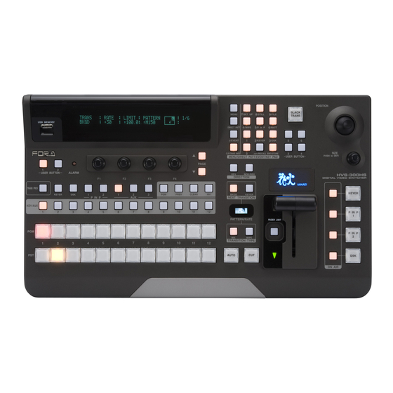
2/KEYER 3/DSK SIZE CLR/TRANS RATE ./RECALL ENT/STORE (DOT) USER BUTTON MENU/DIRECT PATT/EVENT/KEY PAD (PUSH t o DEF) PAGE USER BUTTON ALARM HVS-300HS NOR/REV DIRECTION DIGITAL VIDEO SWITCHER TRANS PREV KEYER KEYER PREV CLEAN BKGD KEYER P IN P NEXT TRANSITION... -
Page 129: Appendix 1. Available File List
File Format File Name File Data Description pm8744xx.mcm HVS-300HS software upgrade data pm8747xx.ocb HVS-30OU software upgrade data xxxxxxxx.mfb HVS-300HS FPGA firmware upgrade data Available USB flash memory Manufacturer Series Name Model Name (Tested memory) SanDisk Cruzer micro, Cruzer mini Series SDCZ2-256... -
Page 130: Appendix 2. Transition Pattern List
Appendix 2. Transition Pattern List 2-1. WIPE Type... -
Page 131: Dve Type
2-2. DVE Type Normal direction... -
Page 132: Index
Index 2D DVE ..........................65 Adding Titles, On-air Tally and Frame Border ................ 77 Additional Inputs ........................29 Adjusting Key Signal ....................... 59 Adjusting Video Signal Levels ....................88 Advanced Auto Transitions ..................... 47 Advanced Settings for Transitions ..................44 Ancillary Data ......................... - Page 133 How to Select Patterns ......................48 How to Set Values ........................17 How to Verify Version ......................108 HVS-300HS .......................... 114 HVS-300HS (Standard Model) ....................2 HVS-300HS / HVS-300RPS ....................112 HVS-300RPS ........................115 HVS-300RPS (Power Redundant Model) ................. 3 HVS-30OU ..........................
- Page 134 Key Edge ..........................64 KEY INSERT MATT ....................... 59 Key Link ..........................58 Key Masks ..........................63 KEYER and DSK ........................56 KEYER Transitions ......................... 40 Loading Data from USB Flash Memory .................. 85 Loading Event at Start-up ....................... 82 Loading Setting Data ......................
- Page 135 Rebooting System ........................93 Recalling Events ........................80 Renaming Files in the USB Flash Memory ................86 Resize Function ........................27 Returning Menu to Default ...................... 21 Returning Parameter to Default....................21 RS-422 Connector ........................7 Safety Area Markers ....................... 90 Saving Data to USB Flash Memory ..................
- Page 136 Upgrading HVS-300HS/RPS ....................108 Upgrading Operational Version .................... 108 USB Flash Memory ........................ 83 USER Button .......................... 22 USER Button (Menu Shortcut)....................16 User Transitions ........................46 Using DIRECT Operation ....................... 80 Using the RECALL Button ...................... 80 Verifying Version ........................107 Video Level Clip ........................
- Page 137 Warning This equipment has been tested and found to comply with the limits for a Class A digital device, pursuant to Part 15 of FCC Rules. These limits are designed to provide reasonable protection against harmful interference when the equipment is operated in a commercial environment. This equipment generates, uses, and can radiate radio frequency energy and, if not installed and used in accordance with the instruction manual, may cause harmful interference to radio communications.
- Page 138 FOR-A America East Coast Office 2 Executive Drive, Suite 670, Fort Lee Executive Park, Fort Lee, NJ 07024, USA Phone: +1-201-944-1120 Fax : +1-201-944-1132 FOR-A America Distribution & Service Center 2400 N.E. Waldo Road, Gainesville, FL 32609, USA Phone: +1-352-371-1505 Fax: +1-352-378-5320...
Need help?
Do you have a question about the HVS-300HS and is the answer not in the manual?
Questions and answers