
Related Manuals for FOR-A HVS-390HS


Summary of Contents for FOR-A HVS-390HS
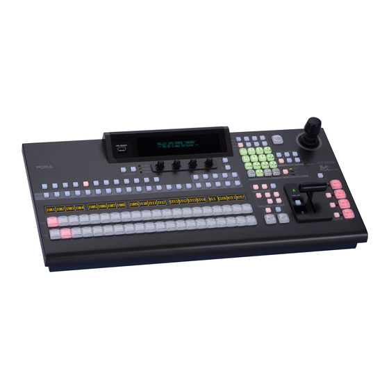
- Page 1 OPERATION MANUAL HVS-390HS Digital Video Switcher HVS-391OU Operation Unit Edition - Rev.1...
- Page 2 Edition Revision History Edit. Rev. Date Description Section, Page 2012/09/14 First edition 2012/12/05 Added M/E CONTROL ON/OFF. p42-43, 179 Added WEB Browser Control. Appendix 3 Corrected factual errors. 2012/12/21 Corrected the event LAST LOAD description. p137 Added HVS-30OU control. Appendix 4 2012/01/30 Added INPUT STILL to user button function.
- Page 3 Precautions Important Safety Warnings [Power] Operate unit only on the specified supply voltage. Caution Disconnect power cord by connector only. Do not pull on cable portion. Do not place or drop heavy or sharp-edged objects on power cord. A damaged cord can cause fire or electrical shock hazards.
- Page 4 [Circuitry Access] Do not remove covers, panels, casing, or access circuitry with power applied to the unit! Turn power off and disconnect power cord prior to removal. Internal servicing / adjustment of unit should only be performed by qualified personnel. Do not touch any parts / circuitry with a high heat factor.
- Page 5 HVS-39VR Virtual Link software (See "HVS-39VR Operation Manual") HVS-39PSM Redundant Power Supply Unit for HVS-390HS HVS-39MB Still and Clip data backup memory option. * Up to 2 input cards of HVS-30HSDI-A / HSD I /HSAI / PCIN can be installed.
-
Page 6: About This Manual
About HVS-390 series system configuration The HVS-390HS is the main unit for HVS-390 series systems. The following standard control panels are available. (HVS-30OU and HVS-30RU can also be used.) These control panels can exist together in the same system. HVS-391OU: A full-featured 1 M/E control panel. -
Page 7: Table Of Contents
1. Prior to Starting ......................... 15 1-1. Welcome ..........................15 1-2. Features ..........................15 2. Panel Descriptions ........................16 2-1. HVS-390HS ........................16 2-2. Control Panel ........................18 2-3. Option Slots ........................20 2-4. Interfaces ........................... 21 2-4-1. EDITOR Connector ....................21 2-4-2. - Page 8 5-9. Frame Synchronizer ......................47 5-10. Bus Matte ......................... 47 5-10-1. Setting the Matte Color ..................... 47 5-10-2. Setting the Gradient Matte ..................48 5-11. Setting up Additional Inputs ..................... 49 6. Video Outputs ..........................51 6-1. Selecting Video for SDI OUTPUT1 and 2 ................51 6-2.
- Page 9 8-10-1. Fader Limit ....................... 80 8-10-2. Transition Rate ......................81 8-10-3. Endpoint Processing for DVE Transitions ..............81 8-10-4. Background Layer of DVE images (Effect Background) ......... 82 9. Modifying Patterns ........................83 9-1. Preset Pattern Groups ....................... 83 9-2. Modified Patterns ......................83 9-3.
- Page 10 11-7-4. FREEZE, STROBE, NEGA, MOSAIC ..............111 11-8. BORDERS ........................112 12. Still Store ..........................113 12-1. Saving Stills ........................113 12-2. Displaying Still Images ....................113 12-3. Backing-up Stills ......................114 12-4. Backing-up Still and Clip Data (HVS-39MB) ..............115 12-4-1.
- Page 11 17-1-1. Creating New Sequences ..................141 17-1-2. Playing Back Sequences ..................142 17-1-3. Quick Recall (Direct Mode) ..................143 17-1-4. Playing Back Sequences Using Advanced Settings ..........144 17-1-5. Editing Sequences: Adding or Inserting Steps ............146 17-1-6. Editing Sequences: Copying and Deleting Steps ..........148 17-1-7.
- Page 12 25-6-4. Copying and Clearing Playlists ................203 25-6-5. Creating New Clips (Recording using VDCP) ............203 26. Connecting to FOR-A MFR Series Router ................205 26-1. Assigning Router Channel to RS-422 port ..............206 26-1-1. Assigning Router Control Function ................. 206 26-1-2.
- Page 13 31-3. Installed Options ......................226 32. Upgrading an Operational Version ..................227 32-1. Upgrade Precedure ....................... 227 32-2. Upgrading HVS-390HS ....................228 32-3. Loading Setting Data ..................... 228 32-4. Bitmap Images for Control Panel Bus Buttons ............. 229 33. Connecting Control and Remote Panels ................231 33-1.
- Page 14 35-1. Specifications ......................... 238 35-2. External Dimensions ...................... 241 35-2-1. HVS-390HS ......................241 35-2-2. HVS-391OU ......................242 Appendix 1. Supported Files ....................... 243 Appendix 2. Transition Pattern List ..................... 244 Appendix 3. HVS-390HS Web-Based Control Appendix 4. HVS-30OU for HVS-390HS Index...
-
Page 15: Prior To Starting
FOR-A provides a wide range of products, from basic support units to complex system controllers, which have been increasingly joined by products for computer video based systems. Whatever your needs, talk to your FOR-A representative. We will do our best to be of continuing service to you. -
Page 16: Panel Descriptions
Unlit installed. Lit red when a cooling fan fails. In such a case, power off the unit and consult your FOR-A supplier. The indicator is normally unlit. ALARM 1 indicator This indicator works the same as the ALARM indicator located on the Control panel. - Page 17 Rear Panel SDI INPUT GEN LOCK RE F IN REF OUT SDI OUTPUT HDMI GPI IN GPI/TALLY OUT TO OU RATING LABEL EDITOR RS-422 A C100-240V 50/60Hz IN A C100-240V 50/60Hz IN OPTION SLOT OPTION SLOT Name Description Refer to sec. Used to input HD/SD SDI video signal.
-
Page 18: Control Panel
ALARM indicates the fan alarm status in the main unit. The indicator blinks red when an alarm occurs. In such a case, power off the system and ALARM indicator consult your FOR-A supplier. The indicator is normally unlit. POWER 1 indicator 31-1... - Page 19 Used to select a bus, then to select a video in the BUS SELECT Block KEY/AUX bus (No 8). 6-2-1 Used to select video for the bus selected in the BUS SELECT block (No. 7). 15-1 KEY/AUX Bus The video can be selected from KEY/AUX bus buttons, PGM, PREV, CLEAN and MV.
-
Page 20: Option Slots
IMPORTANT For further details on system expansion (optional cards) and fan replacement, contact your FOR-A supplier. Slots for Option Cards at Main Unit Rear Panel Two input expansion cards can be installed into Slot A and B. -
Page 21: Interfaces
2-4. Interfaces 2-4-1. EDITOR Connector 9-pin D-sub (male) with inch screws Pin Assignment Table Pin No. Signal Name In/Out Description Frame ground Transmit data (-) Receive data (+) Signal ground Not used Signal ground Transmit data (+) Receive data (-) Frame ground 2-4-2. -
Page 22: Gpi In Connector
The pin assignment shown above is the factory default assignment. Pin assignments can be GPI IN changed via operational menus. See section 24-1-1 " ." GPI IN Circuit Switch or Relay Open collector External Device HVS-390HS External Device HVS-390HS... -
Page 23: Gpi/Tally Out Connector
The pin assignments shown above are the factory default assignments. Pin assignments can be changed via operational menus. See section 24-1-2 "GPI OUT" and 24-2-2 "Tally Output Settings (GPI/TALLY OUT)." GPI OUT/ TALLY Out Circuit HVS-390HS External Device Max voltage: 40V Max load current:... -
Page 24: Gpi/Tally Out Connector (Hvs-391Ou)
2-4-5. GPI/TALLY OUT Connector (HVS-391OU) 15-pin D-sub (female) with inch screws Pin Assignment Table Pin No. IN/OUT Description M/E1 BKGD AUTO TRANS (default setting) M/E1 KEY1 AUTO TRANS (default setting) M/E1 KEY2 AUTO TRANS (default setting) M/E1 KEY3 AUTO TRANS (default setting) M/E1 KEY4 AUTO TRANS (default setting) Not Used (default setting) Signal ground... -
Page 25: Tally Out Connector (Hvs-30Talr)
2-4-6. TALLY OUT Connector (HVS-30TALR) The TALLY OUT connectors are available only when HVS-30TALR cards are installed. Pin Assignment Table (37-pin D-sub, female, with inch screws) Channel Channel Pin No. Output signal Pin No. Output signal TALLY OUT1 Normally Open TALLY OUT10 Normally Open TALLY OUT1 COMMON TALLY OUT10 COMMON... - Page 26 TALLY OUT circuit (Relay output) TALLY OUT HVS-30TALR side External device connector COM. VCC = 24 VDC = 400 mA (max) RELAY The maximum switching current for each output is 400 mA. The HVS-30TALR is a relay board. Use the supplied or commercially-prepared 37-pin D-sub male connector (with #4-40 inch screws) for making a connection cable.
-
Page 27: Connection
3. Connection 3-1. Basic Configuration HD/SD SDI Reference VIDEO SERVER TSG (Reference) VCR, etc. 75Ωtermination SDI INPUT GEN LOCK RE F IN REF OUT SDI OUTPUT HDMI GPI IN GPI/TALLY OUT TO OU RATING LABEL EDITOR RS-422 A C100-240V 50/60Hz IN A C100-240V 50/60Hz IN OPTION SLOT OPTION SLOT... -
Page 28: Optional Configuration
3-2. Optional Configuration TSG (Reference) Reference CAMERA 1 | HD/SD SDI CAMERA 12 VIDEO SERVER VCR. Etc. To IN05 to IN16 ROUTER 75-ohm termination SDI INPUT GEN LOCK RE F IN REF OUT SDI OUTPUT HDMI GPI IN GPI/TALLY OUT TO OU RATING LABEL EDITOR... -
Page 29: How To Connect Between Mu And Ou Units
Arcnet ID (default setting) HVS-391OU HVS-392OU HVS-392ROU HVS-390HS To Change the Arcnet OU ID (1) Connect the MU (HVS-390HS) and an OU (HVS-391OU) via Arcnet using a BNC cable as shown below. MU ID: 250 OU ID: 1 75Ωtermination POWER 1... -
Page 30: Power On
SETUP :>SYSTEM >INPUT >OUTPUT >PANEL MENU :>GPI/TLY >FUNCTION>EXT I/F >STATUS PAGE (5) In the [SETUP - SYSTEM] menu, turn F1 to select ARCNET and then press F1 to display the [SETUP - SYSTEM - ARCNET] menu. SETUP :>FORMAT >REF I/O >ARCNET >ETHERNET SYSTEM... -
Page 31: System Signal Format Selection At Initial Use
3-5. System Signal Format Selection at Initial Use When first switching on your unit, please select a signal format as shown below. (1) The MENU button in the CONTROL block at the right of the menu display should light up at power ON. -
Page 32: Menu Operations
4. Menu Operations 4-1. How to Access Menus 4-1-1. Menu Access Buttons Press MENU in the CONTROL block (see below), which changes the buttons in the SELECT/KEYPAD block to the menu buttons, and then press the buttons on the Keypad to access menus. -
Page 33: Other Menu Access Buttons
4-1-2. Other Menu Access Buttons By pressing once or twice specific buttons in the bus select section or transition control section, the related menus can be displayed. (See the figure and tables below.) MEMO RY MACRO BLA CK WIPE EVENT SEQU ENCE TRA NS USB M EMORY... -
Page 34: How To Set Values
4-2. How to Set Values 4-2-1. Displaying Parameters See section 4-1. "How to Access Menus" to display a desired menu. If a menu has multiple submenus such as the SETUP menu, navigate to submenus following the procedure below. Menu navigation (Example for the SETUP menu) (1) Press MENU in the CONTROL block to the right of the menu display. -
Page 35: Changing Settings Or Values Using F1 To F4
Page no. / Total page INPUT :SELECT :LumGain: Setup :ENABLE : 1/3 PROC AMP: =IN04 : =10.00: =0 : =ON PAGE INPUT :SELECT :ChmGain: :ENABLE : 2/3 PROC AMP: =IN04 : =10.00: =0 : =ON PAGE INPUT :WHT-Lv :Setup :Chroma : Pr-Lv : 3/3 CLIP : =1090 : =-70 : =1110 : =500... -
Page 36: Changing Settings Or Values Using The Numeric Keypad
4-2-3. Changing Settings or Values Using the Numeric Keypad Users can also use the keypad to input numerical settings to a menu. The procedure example for changing the matte color by using the keypad is as follows. (1) Press MENU in the CONTROL block. (2) Press MATT to display the BUS MATT COLOR menu. -
Page 37: Changing Settings Or Values Using The Joystick
4-2-4. Changing Settings or Values Using the Joystick Users can also use the joystick to set position, size and color settings to specific parameters. The menu pages controllable from the JOYSTICK block are shown in the table below. MATT, KEY and MV menu Menu Menu Page Menu... - Page 38 DEF Button See section 4-4-2. "Returning Menus to Default." FINE Button The FINE button allows the user to finely control the joystick when the button lights up. WIPE POS button KEYER (2D DVE) The WIPE POS button is used to quickly access the related menu pages in the WIPE MODIFY menu W IPE POS RO T...
-
Page 39: Copying / Swapping Settings
4-3. Copying / Swapping Settings Keyers can be set up easier with this feature by copying settings from one to another, swapping settings between KEY1 and KEY2, or copying settings from KEY1 to KEY4. 4-3-1. Operation Example: Copying Settings from KEY2 to KEY4 (1) Press COPY/SWAP in the CONTROL block above the Keypad. -
Page 40: How To Return Settings To Default
4-4. How to Return Settings to Default 4-4-1. Returning Parameters to Default Pressing and holding down Control Push-buttons Press and hold the control push-button (F1 - F4) below each parameter to return their settings to factory default. Briefly pressing the DEF button If you need to reset parameters controllable from the JOYSTICK block to factory default, display parameters and press the DEF button. -
Page 41: Video Sources
5. Video Sources 5-1. How to Assign User Names to Sources Video inputs, Still1-4 and StillKey1-4 can be assigned user-specific names, to make them easier to identify for operators. User names can be given to input signals, internally generated black mattes and matte signals, and still pictures. -
Page 42: How To Assign Sources To Bus Buttons
5-2. How to Assign Sources to Bus Buttons Primary and optional video inputs, internally generated signals (black, mattes etc.), captured stills and macros can be freely assigned to any bus buttons using the procedure below. Signal-to-Button mappings are shared on the PGM/PST and KEY/AUX bus. (1) Press MENU, then SETUP to display the SETUP menu top page. -
Page 43: How To Display Signal Names On The Bus Section
Displays text or images in reverse video. 5-4. How to Select an M/E (HVS-39EXTME) The HVS-390HS can expand its system from 1 M/E (mix/effects) to 2 M/E by installing an optional HVS-39EXTME card. Once the HVS-39EXTME is installed, the user can select an M/E to be controlled on the HVS-391OU and use a 2 M/E control panel such as HVS-392OU. -
Page 44: Resize Function
5-5. Resize Function A resize function allows users to input SD signals at the same frame-rate as that in HD mode, and use them as HD images by upsizing. The Resize function is available for the following inputs: IN13 to IN16 4 inputs HVS-30HSDI (extension card) All 4 inputs... -
Page 45: Input Still (Freezing Input Video)
5-6. INPUT STILL (Freezing Input Video) Standard inputs (IN01 to IN16) can display frozen images (INPUT STILLs) by capturing video. Still images for INPUT STILLs can also be uploaded using the FILE menu. (See section 30-3. "Image Data Transfer.") To Freeze Input Video (1) Display [SETUP - INPUT - SIGNAL] menu PAGE 2. -
Page 46: Changing The Side Panel Image
5-7. Changing the Side Panel Image The side panel image of 4:3 video can be changed as shown in the procedure below. (1) Display the [SETUP - INPUT] menu. (2) Turn F1 to select SIGNAL. Press F1 or the page down button to display the [SETUP - INPUT - SIGNAL] menu. -
Page 47: Frame Synchronizer
5-9. Frame Synchronizer A video frame synchronizer is provided for each input (including optional inputs) and is used to synchronize asynchronous signals. Users can select whether to apply frame synchronization to input signals or not (for each signal) as shown in the procedure below. (1) Display the [SETUP - INPUT - SIGNAL] menu. -
Page 48: Setting The Gradient Matte
If you want to adjust the selected color or set the color by entering its HSL values, turn F1, F2 and F3 to enter these values or press F1, F2 and F3, enter a value from the Keypad then press ENTER (from the keypad). Users can also set these three parameters via the JOYSTICK block. -
Page 49: Setting Up Additional Inputs
5-11. Setting up Additional Inputs Up to 4 cards of additional inputs can be installed into slots A and Slot B. L AN SDI INPUT GENLOCK REF IN REF OUT SDI OUTPUT HDM I GPI IN GPI/TALLY OUT TO OU RATING LABEL EDITOR RS-422... - Page 50 HVS-30HSAI available format System Component Component Composite Component standard Component SMPTE BetaCam 1080/59.94i Available Available* Available Available* 720/59.94i 1080/50i, Available Available Available 720/50p 525/60 Available* Available Available* 625/50 Available Available Other standards Available * Video signals with and without 7.5% Setup can be accepted. If a signal with 7.5% Setup is input, the symbol "+"...
-
Page 51: Video Outputs
6. Video Outputs SDI INPUT GEN LOCK RE F IN REF OUT SDI OUTPUT HDMI GPI IN GPI/TALLY OUT TO OU RATING LABEL EDITOR RS-422 A C100-240V 50/60Hz IN A C100-240V 50/60Hz IN OPTION SLOT OPTION SLOT 6-1. Selecting Video for SDI OUTPUT1 and 2 SDI OUTPUT1 and 2 on the MU rear panel can output only M/E combined videos. -
Page 52: Selecting Video Via Bus Buttons
6-2-1. Selecting Video via Bus Buttons (1) Press an AUX button, from AUX1 to AUX8 indicated below. PG M PREV CLEAN M V1 M V2 KEY ER AU X KEY /AUX (2) Press a button in the KEY/AUX bus section to select a signal for the selected AUX output. PG M PREV CLEAN... -
Page 53: Aux Video Switching With Effects
6-2-3. AUX Video Switching with Effects The background video displayed on an AUX bus can be easily switched using effects. The auxiliary video can be changed using crossfade, horizontal or vertical wipe transitions. This chapter explains how to switch AUX video using two operational examples. Ex. -
Page 54: Preview Set Up
6-3. Preview Set Up The switcher does not have a dedicated PREVIEW output. The preview bus output can be assigned to, however, an SDI OUTPUT or AUX output. Users can also add the key images to PREVIEW. This can be done as explained below: 6-3-1. -
Page 55: Clean Set Up
6-4. Clean Set Up The switcher can output the CLEAN video via an auxiliary output. Users can also add the KEY image to CLEAN. Follow the procedure below to assign the clean video to an AUX output. AUX3 is used in this example Routing an M/E1 Clean Video to AUX Output (1) Quickly press AUX1 twice in the BUS SELECT block to display the [SETUP - OUTPUT- OUT XPT](1/4) menu. -
Page 56: Hd Multiviewer Video Output In Sd Mode
Ex. 2 Switcher's System Format: 720/50p To Output the AUX1 video (at 1280 x 720 resolution): OUTPUT : XPT :FORMAT : FRQ :MV HQ : 3/4 HDMI OUT: =AUX1 =HDTV : =--- : =--- Ex. 3 Switcher's System Format: SD PAL (625/50) To Output the MV1 SVGA video at 50Hz: OUTPUT : XPT... -
Page 57: Setting Up And Outputting Key Out
6-6. Setting Up and Outputting KEY OUT The KEY OUT signal (switcher processed key cut signal) can be assigned to AUX outputs. Various kinds of key cut signals can be used for KEY OUT sources. KEY OUT signals are useful for purposes such as checking key signals while processing chroma keys. -
Page 58: Setting Up Additional Outputs
6-7. Setting Up Additional Outputs Up to two cards of additional outputs can be installed into slots C and D. SDI INPUT GEN LOCK RE F IN REF OUT SDI OUTPUT HDMI GPI IN GPI/TALLY OUT TO OU RATING LABEL EDITOR RS-422 A C100-240V 50/60Hz IN... - Page 59 If HVS-30HSAO is installed: System format Channel FORMAT setting ASPECT setting HD Component ----- HD Component ----- SD Component, 4:3, SQUEEZE, LETTER Composite * Component * Ch1, (SMPTE or BetaCam level), ----- Composite * * You can choose whether to add 7.5% Setup to the output signals if the switcher is running in 59.94 Hz mode.
-
Page 60: Aux Link
6-8. AUX LINK In the AUX-LINK function, the auxiliary outputs are grouped, and the master and slave outputs are set to allow all slave output signals to be switched simultaneously by simply selecting the master output signal. A group consists of one master output and up to three slave outputs. Seven auxiliary output groups can be set. -
Page 61: Creating Signal Link Groups
6-8-2. Creating Signal Link Groups (1) Press the page down button to go to the [AUX LINK - LINK GRP] menu. FUNCTION:SELECT:MASTER: SLAVE SEL/AUX : 3/3 LINK GRP: =1 : =IN01:1=IN02 2=IN03 3=IN04 Available Signals BLK, IN01 to IN24, STL1 to STL4, STK1 to STK4, CB, MAT1, MAT2, M/E M1PG, M1PV, M1CL, M1KY, (If AUX1-8 is selected for the... - Page 62 Press AUX1 in the BUS SELECT-AUX block and select IN01 on the AUX/KEY bus: >> IN02 is assigned to AUX2, IN03 to AUX3 and IN04 to AUX4. Press AUX7 in the BUS SELECT-AUX block and select M/E1 PGM: >> M/E1 PREV is assigned to AUX8. Select IN05 in M/E2-PGM bus: >>...
-
Page 63: Bus Operation
ALARM W IPE POS KEY1 KE Y2 KEY3 KEY4 POWER1 PAGE POWER2 ME NU FINE HVS-390HS USER BUTTON JOYSTICK DIGITA L VIDEO SW I T CHER PLAY CU T BKGD C L E A R RECALL STORE E NTE R... -
Page 64: Selecting Video Sources For Aux Outputs
To Change the M/E Bus Indication Color: The M/E bus indication color can be changed from green to red. (Available only when HVS-390HS has two M/E banks and the OU controls M/E1.) Select GRN under ON AIR and press ENTER in Keypad. -
Page 65: To Assign The Shift Function To A Bus Button
7-3-1. To Assign the SHIFT Function to a Bus Button: (1) Press MENU in the CONTROL block, then press SETUP to display the SETUP menu top page. Turn F1 to select INPUT. Press F1 or the page down button to display the [SETUP - INPUT] menu. -
Page 66: Transitions
8. Transitions Available Transitions on the M/E BLACK transition Backgrounds: CUT, MIX and Pattern transitions KEY1 and 2: CUT, MIX and Pattern transitions SLIDE (4-direction), SCALER and WIPE (4-direction) transitions KEY3 and 4: CUT and MIX transitions SLIDE (4-direction), SCALER and WIPE (4-direction) transitions -Transitions setup by next transition bus selection -Transitions using the AUTO button or fader lever... -
Page 67: Transition Block Description
8-1. Transition Block Description TRAN SITION RA TE KEY 1 NOR /REV PATT ERN DIRECTION BKGD KEY1 KE Y2 FADER LIMIT KEY 2 KEY3 KE Y4 NEX T TRANSITION KEY 3 W IPE TRANSITION TYPE ‚c‚u‚d AUTO KEY 4 ON AIR ... -
Page 68: Quick Reference For Available Transitions
8-2. Quick Reference for Available Transitions Fader Pattern Type Rate Transition Execute Button or Tool Refer to Limit Direction BLACK BLACK Available BLACK TRANS button Available BKGD >> CUT button Available Available BKGD >> MIX >> AUTO button BKGD Available NOR/REV Fader lever Available Available... -
Page 69: Background Transitions
8-4. Background Transitions This chapter explains how to perform background transitions. CUT Transition (1) Select a video source in the PST bus block. (2) Press the BKGD button in the NEXT TRANSITION block. (3) Press CUT to perform the background CUT transition. TRAN SITION RATE NOR /REV... -
Page 70: Key Transitions
8-5. KEY Transitions Key images are displayed on the M/E (background) output screen. This chapter explains how to perform key transitions using M/E1KEY1 as an example. (1) Perform key setup for the KEY. (See section 10. "KEY.") (2) Perform a desired transition referring to the below procedures. ... - Page 71 Pattern transition (1) Press KEY1 in the NEXT TRANSITION block. (2) Press WIPE in the TRANSITION TYPE block. (3) Press PATTERN to display the [WIPE PATTERN] menu. (4) Turn F2 or F3 to select a desired pattern. (See section 8-8 "How to Select Patterns.") WIPE :BKGD :KEY1...
-
Page 72: Simultaneous Bkgd And Key Transitions
8-6. Simultaneous BKGD and Key Transitions Background and key transitions can be performed simultaneously. This chapter explains how to perform simultaneous BKGD, KEY1 and KEY2 transitions as an example. (1) Set transition types for the background, KEY1 and KEY2 to MIX or WIPE respectively. Select a pattern using the menu if set to WIPE. -
Page 73: Pattern (Wipe/Dve) Transitions
8-7. Pattern (WIPE/DVE) Transitions Pattern transitions are available for Background, KEY1 and KEY2.. This section explains how to perform pattern transitions. (1) Select a next background video on the PST bus. Before performing a KEY1 or KEY2 transition, perform keyer setup. (2) Press BKGD, KEY1 or KEY2 in the NEXT TRANSITION section to select a bus to be transitioned. -
Page 74: How To Select Patterns
8-8. How to Select Patterns Wipe patterns are available for background and KEY transitions. More than 150 preset patterns are provided. This chapter explains how to select patterns for transitions, verify the currently selected pattern and select patterns quickly, using the Direct Pattern function. 8-8-1. - Page 75 M EMO RY BLAC K M A C R O W IP E E V ENT S EQ UE NCE TR AN S CO NTRO L C O P Y /S W A P S E Q E D IT MENU US ER B UTTO N ATTACH...
- Page 76 (5) Turn F3 to change OVER WR (Overwrite) to ON to set overwrite protection. DIRECT :PATTERN :OVER WR:DELETE : 1/1 RECALL : =020 : =OFF NOTE Before setting overwrite protection, set DIRECT to OFF. Otherwise, the selected pattern is set immediately when pressing the number button. To Clear a Direct Pattern Registration Individually (1) Press WIPE in the MEMORY block.
-
Page 77: Key In/Out Effects
8-9. Key IN/OUT Effects Key transitions can be performed not only through the BKGD AUTO button and fader lever, but also through key ON AIR and key AUTO buttons.(See figure below.) KEY ON AIR and KEY AUTO are multiple function buttons. CUT, MIX, SLIDE (4 types) and WIPE (4 types) transitions can be performed using these two buttons for each key. -
Page 78: Setting The Key On Air Button Function (User Transition)
8-9-1. Setting the KEY ON AIR Button Function (USER Transition) The KEY ON AIR function is set to CUT as factory default. To set KEY1 ON AIR on M/E1 to SLIDE TOP, proceed as follows: (1) Press the TRANSITION RATE button above the KEY1 ON AIR button to display the [TRANS] menu. -
Page 79: Setting The Key Auto Button Function
8-9-2. Setting the KEY AUTO Button Function The KEY AUTO buttons are set to AUTO (MIX) as factory default. To change the KEY2 ON AIR button function on M/E2 so that CUT transitions can be performed by briefly pressing the button and KEY2 AUTO (MIX) transitions can be performed by pressing and holding down the button, proceed as follows: (1) Press the TRANSITION RATE button above the KEY ON AIR buttons to display the [TRANS] menu. -
Page 80: Advanced Settings For Transitions
8-10. Advanced Settings for Transitions 8-10-1. Fader Limit The fader limit setting determines how far your transition can proceed. When performing transitions (mix or other) there may be times when you want the transition to the next signal to only complete to a certain degree instead of fully switching from one picture to another. In such case, you will need to limit the fader range. -
Page 81: Transition Rate
8-10-2. Transition Rate The transition rate setting determines how long the transition takes in frames to complete. (1) Press the TRANSITION RATE button in the transition section to display the [TRANS] menu. Users can also display the [TRANS] menu by quickly pressing the following buttons twice: BKGD, KEY1, KEY2 and MIX in the NEXT TRANSITION block. -
Page 82: Background Layer Of Dve Images (Effect Background)
8-10-4. Background Layer of DVE images (Effect Background) The effect background is the bottom layer placed below the DVE effects. It is used to transition images with a 2Ch-DVE pattern. Effect background DVE image (1) Press the TRANSITION RATE button to display the [TRANS] menu. TRANS :BKGDTRS:EFF BGD: :BLK TRS: 1/4... -
Page 83: Modifying Patterns
9. Modifying Patterns 9-1. Preset Pattern Groups The WIPE preset patterns (No. 0-202) can be changed or modified from their original patterns. Basically the preset patterns are categorized into five different groups. The available items in the WIPE modify menu are also different according to the type of groups Pattern No. -
Page 84: Pattern Modify Example 1 (Pattern 20)
SWAP KEYER (2D DVE) M ENU STILL M ATT FILE DETT ACH WIPE POS KEY1 KEY2 KEY3 KEY4 M ENU FINE HVS-390HS JOYSTICK DIGITAL VIDEO SWITCHER PL AY AD D BKGD CLEAR RECALL STORE ENTER KEY1 STOP COPY PASTE OVWR... -
Page 85: Pattern Modify Example 2 (Pattern 117)
ME1 WPBG: BORDER COLOR :RECALL : 2/2 BORDER :S=66.3 L=5.4 H=3.5 : >BLUE : 9-4. Pattern Modify Example 2 (Pattern 117) This modification example also adds a border effect to KEY1 transitions on M/E1 using Pattern 117. However Pattern 117 has different border settings than Pattern 20. It can use both inside and outside border effects. -
Page 86: How To Reset The Wipe Menu
9-5. How to Reset the WIPE Menu To Reset a Modified Pattern using the WIPE PATTERN Menu: (1) Press PATTERN in the TRANSITION block to display the [WIPE PATTERN] menu. The letter "M" appears in front of the modified pattern. WIPE :BKGD :KEY1... -
Page 87: Wipe Menu
9-6. WIPE Menu 9-6-1. No. 0-99 The pattern number is displayed instead of "0XX" in the top page of the submenu. The M/E number is displayed instead of "X" and "BG" (BKGD), "K1"(KEY1) or "K2"(KEY2) is displayed instead of "XX" on each page. MEX WPXX:>BORDER >POS/ANGL>MULTI >SUB EFF... -
Page 88: No. 100-137
9-6-2. No. 100-137 The pattern number is displayed instead of "1XX" in the top page of the submenu. The M/E number is displayed instead of "X" and "BG" (BKGD), "K1"(KEY1) or "K2"(KEY2) is displayed instead of "XX" on each page. MEX WPXX:>BORDER >POS/ASP >CROP >SUB EFF... -
Page 89: No. 140-147, 150-157, 161 And 162
9-6-3. No. 140-147, 150-157, 161 and 162 The pattern number is displayed instead of "1XX" in the top page of the submenu. The M/E number is displayed instead of "X" and "BG" (BKGD), "K1"(KEY1) or "K2"(KEY2) is displayed instead of "XX" on each page. MEX WPXX:>BORDER >TURN >CROP... -
Page 90: No. 170-181
9-6-4. No. 170-181 The pattern number is displayed instead of "1XX" in the top page of the submenu. The M/E number is displayed instead of "X" and "BG1" (BKGD CH1) or "BG2"(BKGD CH2) is displayed instead of "BGx" on each page. MEX WPBX:>BORDER1 >CROP1 >SUB EFF1>CG WIPE No.1XX :>BORDER2 >CROP2 >SUB EFF2>INIT... -
Page 91: Key
10. KEY The key feature enables you to superimpose titles and images onto background signals. With the HVS-390 series, four key channels are provided for each M/E. Three key types are available in all keyers: Luminance Key, Full Key and Bus Key. Key Invert, Mask and 2D DVE effects can also be added to keys. -
Page 92: Luminance Key
Bus key Bus Key, also called External Key, uses different images for Key Source and Key Insert. The background signal is cut out using Key Source and Key Insert fills in the cut out part of the signal. Bus key INVERT BOX(OR) mask... -
Page 93: Full Key
10-2. Full Key (1) Follow Step (1) to Step (4) in "Luminance Key" above. (2) The [M/E1 KEY1 - INS/SRC] menu is displayed. Turn F1 to set TYPE to FULL. The insert signal can also be selected at INSERT. ME1 KEY1: TYPE :INSERT :SOURCE :INVERT : 1/4 INS/SRC : =FULL... -
Page 94: Key Link
10-3-1. Key Link A Key Source signal is automatically selected when a Key Insert signal is selected if KEY LINK is on. The INSERT/SOURCE signal pairs for Bus keys are automatically set once they are selected for a key. To change signal assignment, select the INSERT/SOURCE signal pair again for the key or another key. -
Page 95: Key Insert Aux
10-4. KEY INSERT AUX The KEY INSERT AUX allow users to replace key fill (INSERT) images using an AUX bus (AUX5 to AUX8), changing only inside images while maintaining key shapes. Change KEY INSERT Change the AUX5 to AUX5. image. (1) Set up a bus referring to Section "10-3. -
Page 96: Adjusting The Key Signal
10-5. Adjusting the Key Signal Clip and Gain allows users to adjust the key signal and its composition over the background. The transparency of the KEY can also be adjusted. (1) Quickly press KEY1 twice in BUS SELECT, and display the [M/E1 KEY1 SETUP] menu. (2) Turn F1 to select INS/SRC, and press F1 or the page down button. -
Page 97: Chroma Key
10-6. Chroma Key Chroma key is a method for creating a key signal using a chroma component instead of a luminance component. It is mostly used for compositing moving subjects such a person in the virtual background. For example, to place a person onto a background graphic, first film the person standing in front of a background such as a blue screen. -
Page 98: Chroma Key Adjustments
(11) Press MENU in the Joystick block. Move the joystick up, down left and right to move the crosshair cursor onto the desired color. Pressing the FINE button will help you fine tune the adjustment. To precisely adjust the position, press F1 or F2, enter the values directly into POSITION X and Y using the numeric keypad and then press ENTER. - Page 99 Chroma Key Mix Mode 1 (CK MODE) Set a mix mode 1 for chroma keys suitable to the background image under CK MODE in PAGE 2. ME1 KEY1: CK EDGE :CK MODE:CK MASK: 2/5 CK ADJT :L=0 : =NORML: =NORML: CK MODE setting Description NORMAL...
-
Page 100: Advanced Example 1 (Using Key Insert Aux)
10-6-3. Advanced Example 1 (Using KEY INSERT AUX) This example replaces Chromakey images while maintaining the key shape by selecting InMAT (insert matt) or AUX5 to 8 for KEY INSERT. (See section 10-4. "KEY INSERT AUX.") Replace the chroma key image to a matt or other image. -
Page 101: Mask And Invert
10-7. Mask and Invert Mask and Invert can be used for all keys. Preset masks are available only for KEY1 and KEY2. Bus key INVERT BOX(OR) mask 10-7-1. Inverting Key and Background Setting Invert to ON inverts the key image and the background image. Set INVERT in the [M/E1 KEY1 - INS/SRC] menu to ON. - Page 102 Signal Mask Video inputs can be used for mask signals instead of Box. Inputs used for masks must be assigned to AUX5 to AUX8. Combined video signals such as program or multi-view cannot be used. (1) Open the [M/E1 KEY1 - MASK] menu PAGE 1. (See the previous page.) (2) Turn F3 to select a mask signal.
-
Page 103: Key Edge
10-8. Key Edge The EDGE function allows users to add border type edges on KEY1 and KEY2. Two types of edges are available: Normal and Outline. The width, transparency, and color can be set for the edges. Shadow effects can also be added by changing the position of the edges. This chapter shows how to add a key edge using M/E1 KEY1 as an example. -
Page 104: Where Key3 And Key4 Appear
10-9. Where KEY3 and KEY4 Appear The KEY3 and KEY4 images appear on each M/E program screen as a factory default setting. Users can change the destination of KEY3 and KEY4 to AUX1 to 8. To do this, follow the procedure below. -
Page 105: Dve Effects On Keys
11. DVE Effects on Keys Dedicated 2D-DVE(2.5D) effects are available for each key in the standard configuration. The 2D-DVE is available just by setting the 2D DVE item to ON in each key menu. As an example, this section explains how to add a 2D-DVE effect on KEY1. 11-1. -
Page 106: Changing Sizes Or Aspect Ratios
Changing Positions Using the Menu (1) Display the [M/E1 KEY1 - POS/SIZE], menu PAGE1. (2) Turn F1 or F2 to set the position of the KEY1 image. ME1 KEY1: POSITION : SIZE :2D DVE : 1/5 POS/SIZE:X=0 : =500 : =ON The base original POSITION of a key is at the center of the output screen. -
Page 107: Fade
11-4. FADE FADE allows users to add an effect to make backgrounds transparent. (1) Go to the [M/E1 KEY1 - POS/SIZE] menu PAGE 2. (2) Turn F3 to set the FADE level for the KEY1 image. Increasing the value makes the backgound transparent. -
Page 108: Setting Example
11-5-1. Setting Example (1) Set the key position and size on PAGE 1 of the [M/E1 KEY1 - POS/SIZE] menu. Note that the position is two-dimensional and its origin is placed on (0, 0), which coincides with the center of the screen. The position values are the distance between the origin and the center of the KEY1 images, which will be a positive value if the center of the key image is above the origin and negative value if it is below the origin. -
Page 109: Crop
[Example 2] Rotation around the Y-axis POSITION (-200,-200) SIZE 500 CENTER POSITION (150,-200,-400) LOCAL ROTATION (0,0,100) Center of rotation Screen surface Point of view [Example 3] Rotation around the Z-axis POSITION (-200,-200) SIZE 500 CENTER POSITION (150,-200,-400) ROTATION (0,0,100) Center of rotation Screen surface Point of view... -
Page 110: Sub Effect
11-7. SUB EFFECT The SUB EFFECT menu allows users to add MONO COLOR, DEFOCUS, and PAINT COLOR effects. Access the SUB EFFECT menu as shown below. (1) Press MENU in the CONTROL block, then the KEY1 button to display the [M/E1 KEY1 SETUP] menu. -
Page 111: Freeze, Strobe, Nega, Mosaic
11-7-4. FREEZE, STROBE, NEGA, MOSAIC Freeze, strobe, negative, and mosaic effects are also available. (1) Go to the [M/E1 KEY1 - SUB EFF] menu PAGE 3. ME1 KEY1:FREEZE :STROBE : NEGA :MOSAIC : 3/3 FREEZE :=OFF : =OFF : =OFF : =OFF (2) When applying these effects, please refer to the table below. -
Page 112: Borders
11-8. BORDERS Borders can be added to key images. Inside border and outside borders can be adjusted independently. (1) Go to the [M/E1 KEY1 - BORDER] menu. (2) To use the inside border, set the width at the INSIDE X and Y. To use the outside border, set the width at the OUTSIDE X and Y. -
Page 113: Still Store
12. Still Store The switcher can capture and memorize up to four Video and Key still pictures from the switcher output video. Once captured stills are assigned to bus buttons (See section 5-2. "How to Assign Sources to Bus buttons" ), they can then be used as key fill and source signals, M/E background and AUX output signals. -
Page 114: Backing-Up Stills
12-3. Backing-up Stills To Save Still Images: (1) Press MENU in the CONTROL block, then STILL in the Keypad to display the [STILL] menu (2) Press page down to go to PAGE 3 ([STILL BACKUP] menu). (3) Turn F1 to select a still to be backed up to the backup memory. (4) Turn F2 to select SAVE>. -
Page 115: Backing-Up Still And Clip Data (Hvs-39Mb)
12-4. Backing-up Still and Clip Data (HVS-39MB) To use the still and clip automatic backup feature, an HVS-39MB should be installed to your switcher. An HVS-39MB option allows you to automatically save all still and clip backup data. Automatic backup is performed every time the user stores an image or clip to a buffer, STILL1-4, INPUT_STILL1-16 or CLIP1-4. -
Page 116: Loading Backup Data
Automatic backup is enabled or disabled for all STILL1-4, INPUT_STILL1-16 and CLIP1-4, images and cannot be set individually for each file. 12-4-2. Loading Backup Data (1) In [STILL] menu PAGE 4, Turn F1 to select a still or clip for backup from STILL1 to 4, INPUT_STILL1 to16 and CLIP1 to 4. -
Page 117: Managing Clips
13. Managing Clips Clip stores allow you to record and play output video. Up to four video and key pair signals can also be recorded simultaneously. Clip data can be stored in four still memory buffers with still data. In addition, sequential image files can be transferred from a computer and saved in the memory as a video clip. -
Page 118: Recording Video And Key Signals Simultaneously
13-1-2. Recording Video and Key Signals Simultaneously Assume a video signal is assigned to AUX1 and its key signal to AUX2. If you need to record an input signal such as IN01, assign the signal to an AUX bus before recording. -
Page 119: Playing Clips
13-2. Playing Clips 13-2-1. Ex. 1: Playback on PGM Bus This example shows how to play the PGM clip recorded in section 13-1-1 on the background through STILL1. Assume that STILL 1 is assigned to the bus button 1 . (1) Open PAGE 1 in the [STILL] menu. -
Page 120: Clearing Clip Data
(8) Go to PAGE 4 in the [STILL] menu. Turn F1 to select STIL1 (STILL1) and set the IN and OUT points, then press F4. STILL :SELECT :CUR(100): : OUT : 4/6 CLIP =STL1 : =78 : >100 : F=60 (9) Go to PAGE 6 in the [STILL] menu. -
Page 121: Cg Wipe
14. CG WIPE CG WIPE allows you to create a sequence in which a CG video, which is displayed using a KEY, moves in accordance with the motion of a WIPE pattern. Normally patterns used for CG WIPE are modified according to sequences. ... -
Page 122: Cg Wipe Operation Example 1
14-1. CG WIPE Operation Example 1 Ex. 1: CG WIPE using STILL1 and KEY1 In this example, it is assumed that a CG (V + K) is stored in STILL1. Assign STILL1 and STILL KEY to KEY1 signals, display KEY1 on the screen and play the CG through KEY1. Then set CG WIPE to ON, and perform a background transition. -
Page 123: Cg Wipe Operation Example 2
IN/OUT points, transition rate and delay values to adjust the CG WIPE sequence, if needed. <Connection> Connect the switcher to a VTR in which CG is stored as shown below. VDCP device RS-422 HVS-390HS L AN SDI INPUT GENLOCK REF IN... - Page 124 <Setting Up BKGD> (1) Press BKGD in the transition section. (2) Press WIPE to set the BKGD transition type to WIPE. (3) Press PATTERN in the transition section to display the [WIPE PATTERN] menu, then press F1 to enter a desired pattern number on the keypad. Then press ENTER to confirm the selection.
-
Page 125: Saving Cg Wipe Settings
<Performing CG WIPE> (1) Verify that the background transition type is set to WIPE and the modified WIPE pattern is properly selected. Press the AUTO button to perform a CG WIPE sequence. (2) Adjust time or positioning using the related menu items, as needed. 14-3. - Page 126 Table 2. If VTR1-4 is used for CG playback Menu item Default Setting Description Fig. 1 ENABLE OFF, ON Sets CG WIPE ON/OFF. Selects a channel through which a CG is VTR1 to 4 played back. 0 to 999 Sets the CG playback time.
-
Page 127: Multiviewer
The multiviewer allows users to monitor multiple images such as video sources input to the switcher and internally generated or combined images on the same screen. The HVS-390HS provides two multiviewer outputs, with each output having three types of split displays: quad, 10 and 16 way. -
Page 128: Selecting The Split-Screen Type
15-2. Selecting the Split-screen Type The type of split-screen to be used can be selected in the [SETUP - OUTPUT-MV1] menu. There are three different types. (1) Quickly press MV1 twice in the KEY/AUX block to display the [SETUP - OUTPUT- MV1] menu. -
Page 129: Setting Up Each Split Area
15-4. Setting Up Each Split Area 15-4-1. Titles (1) Quickly press twice the MV1 button in the KEY/AUX block to display the [SETUP - OUTPUT - MV1] menu. (2) Turn F2 to select a channel number (split area) of the split screen under the SCREEN item. -
Page 130: Audio Level Meter
Changing Output Signal Names Open the [SETUP - OUTPUT - RENAME] menu and change names, as necessary. OUTPUT :SELECT :SHORT : LONG NAME(MV) : 1/1 RENAME : =M1PG : =M1PG : =M/E1 PGM SELECT SHORT (Defalt) LONG NAME (Default) Description M1PG to M2PG M1PG to M2PG... -
Page 131: On-Air Tally
15-4-2. On-air Tally The tally indicates which video is currently On-air (output from the program) and which is set to be the next output. The multiviewer can display two types of tally indicators: Frame and Marker. You can use either or both at the same time. (1) Display [SETUP - OUTPUT - MV1] menu PAGE 5. -
Page 132: Event Memory
16. Event Memory The switcher can save control panel setup statuses as data for recall when needed. This function is called Event Memory. This Event Memory function enables quick recall of the same setting statuses that were previously saved. The event memory data can accurately reproduce statuses of button assignments and selections including a re-entry of M/E1 PGM on the control panel, because the event memory data holds all panel information. - Page 133 Detailed Data Selection for Saving Events Data saved to the event can be selected under the [EVENT MEMORY] menu or [EVENT STORE] menu as shown below. [EVENT MEMORY] menu Item Setting Description *RATE OFF, 1 to 999 See section 16-2-3. "Transitions Using Event Recall." AUX BUS ON, OFF Setting to ON stores all AUX bus data.
-
Page 134: Recalling Events
EVENT :AUX SEL:AUX RCL:KEY ASG:SEQ RCL: 2/3 STORE : =AUX1 : =OFF : =OFF : =OFF :P.00 EVENT :CG WIPE: : 3/3 STORE : =OFF :P.00 IMPORTANT User Default Settings for the [EVENT STORE] menu The same items (RATE, KEY ASG and DEQ RCL) in the [EVENT MEMORY] menu and [EVENT STORE] menu link together. -
Page 135: Using The Recall Button
16-2-2. Using the RECALL Button To Recall Events (fastest method): (1) Press EVENT in the MEMORY block. (2) Press the number button where the needed data M E MO R Y is to be stored. MACRO W I P E EVE NT SEQU ENCE (3) Press RECALL. -
Page 136: Transitions Using Event Recall
16-2-3. Transitions Using Event Recall The RATE item in the EVENT menu allows users to set the duration time (transition rate) for loading events. With this duration time, transition sequences of two steps (statuses before and after recalling events) can be performed. The two images (keyframes) before and after recalling events that appear on program screens are automatically interpolated to create a smooth transition in the same way as the Sequence feature. -
Page 137: Overwrite Protection
16-3. Overwrite Protection (1) Press EVENT in the MEMORY block. (2) Press the number button where the needed data is stored. The button will start flashing when pressed. The [EVENT RECALL] menu will be automatically displayed. (3) Press the page down button to go to PAGE 3. (4) Turn F2 to change OVER WR to DISBL(disable) to set the write protection on the memory button. -
Page 138: Setting The User Default Menu When Storing An Event
16-5. Setting the User Default Menu when Storing an Event The [EVENT STORE] menu appears as shown below in the factory default setting when storing events. EVENT :SELECT : XPT : DATA : RATE : 1/3 STORE : =ALL : =ON : =ON : =0 :P.00... - Page 139 (5) Turn F3 to select the desired panel setup in the table below LOAD setting Description The switcher starts with Last Saved Settings. "Last Saved Settings" are automatically saved when the unit is rebooted or SETUP is pressed. The switcher starts with the last loaded event. LAST Note that to enable the Last Load function, an event must be loaded after setting to LAST.
-
Page 140: Sequence Operation
17. Sequence Operation A sequence is a function for joining individual images into a sequential video and recalling it for playback in a single operation. Each sequence is composed of video frames called steps. To make sequences, create an initial step and save it to the sequence working memory, then create the next step and to save to the working memory and so on. -
Page 141: Sequence Operation Examples
17-1. Sequence Operation Examples 17-1-1. Creating New Sequences The operation example in this section shows how to create a new sequence in three steps and store it to "Sequence Memory 0." M E MO R Y MACRO W I P E EVE NT SEQU ENCE C O NTR O L... -
Page 142: Playing Back Sequences
17-1-2. Playing Back Sequences The operation example in this section shows how to recall and play the sequence that was created in the previous section and saved to "Sequence Memory 0." M E MO R Y MACRO W I P E EVE NT SEQU ENCE Recalling the Sequence... -
Page 143: Quick Recall (Direct Mode)
17-1-3. Quick Recall (Direct Mode) The operation example in this section shows how to recall the sequence that was saved to "Sequence Memory 0" using Direct mode. (1) Press SEQUENCE to change the Keypad to SEQUENCE mode. M E MO R Y (2) Press 0 to select "Sequence Memory 0."... -
Page 144: Playing Back Sequences Using Advanced Settings
17-1-4. Playing Back Sequences Using Advanced Settings Playing Sequences by Changing Bus Signal Selections Sequence data includes that on bus signal selection states and are basically recalled on the control panel exactly the same that they were stored. For example, if Bus Button 1 was selected in the PGM bus and Bus Button 2 in the PST bus in the sequence, these buttons should be selected in the same way when recalling the sequence. - Page 145 Playing Sequences Using the Fader Lever The playback of sequences can be played back using the fader lever. To do this, follow the procedure below. (1) Open PAGE 1 in the [SEQ EDIT] menu. (2) Set LINK to ON. SEQ EDIT: LOOP : DIR : LINK...
-
Page 146: Editing Sequences: Adding Or Inserting Steps
17-1-5. Editing Sequences: Adding or Inserting Steps The operation example in this section shows how to recall "Sequence Memory 0" that was stored in section 17-1-1, edit the sequence by adding and overwriting steps to create a new sequence with four steps, and store it to "Sequence Memory 1." Sequence Memory 0 For storing to Sequence Memory1 ... - Page 147 Overwriting Step 3 (1) Press SEQ EDIT to change the Keypad to SEQ EDIT M E MO R Y mode and display the [SEQ EDIT] menu. MACRO W I P E EVE NT SEQU ENCE (2) Press the page down button to go to PAGE 2. Verify C O NTR O L the current step.
-
Page 148: Editing Sequences: Copying And Deleting Steps
17-1-6. Editing Sequences: Copying and Deleting Steps This section explains how to copy, paste and delete steps. The operational example below shows how to create a sequence having 5 steps with the first and last steps the same. Creating a New Sequence M E MO R Y (1) Press SEQ EDIT to change the Keypad to Sequence MACRO... -
Page 149: Editing Sequences: Setting Interpolation And Duration
17-1-7. Editing Sequences: Setting Interpolation and Duration This section explains how to set the interpolation mode and the playback time using KEY1 as an example. Smoothing Movements for KEY1 (Interpolation Mode) At factory default settings, the movements between steps for the backgrounds and keys are linearly interpolated. -
Page 150: Sequence Menu And Keypad Mode
17-2. Sequence Menu and Keypad Mode In Sequence Operations the Keypad automatically changed its mode according to the displayed menu. The Keypad is in Sequence mode when the [SEQUENCE MEMORY], [SEQUENCE STORE] or [SEQUENCE RECALL] menu is displayed. The Keypad is in SEQ EDIT mode when the [SEQUENCE EDIT] menu is displayed. -
Page 151: Seq Edit Mode
The SEQUENCE RECALL menu In SEQUENCE mode, pressing a memory button that has data on the Keypad opens the [SEQUENCE RECALL] menu. This menu is used to recall a sequence to the sequence working memory. The overwrite protection for the sequence memories can also be set in this menu. - Page 152 Item Description Refer to Moves between steps. INC (INCREMENT) 17-1-5 DEC (DECREMENT) 17-1-6 PLAY Plays back a sequence. 17-1-2 Pressing the button during playback pauses the playback. STOP Stops sequence play. 17-1-2 Creates a new sequence by clearing the working memory 17-1-1 data.
-
Page 153: Sequence Memory Operation Examples
17-3. Sequence Memory Operation Examples 17-3-1. Setting Overwrite Protection on Sequence Memory 2 (1) Press SEQUENCE to display the [SEQUENCE MEMORY] menu. (2) Press 2 to select "Sequence Memory 2." The button light turns on and the [SEQUENCE RECALL] menu appears. (3) Press the page down button to go to PAGE 2 of the menu. -
Page 154: Macros
18. Macros The Macro function allows users to perform a sequence of recorded operations with the single push of a button. The keypad is used to record and execute macros. The macro memory data can be backed up and then restored from USB flash memory drives. (See section 19 "File Operations.") 18-1. -
Page 155: Executing Macros
18-2. Executing Macros (1) Press MACRO in the MEMORY block. (2) Turn F1 to select an event page in the [MACRO MEMORY] menu. MACRO : PAGE :DIRECT :PAGECLR: : 1/3 MEMORY : =OFF : =OFF (3) Press the number button to which the needed data is to be stored. M E MO R Y If DIRECT mode is ON, macros are executed by just MACRO... -
Page 156: Operation Example 2
18-4. Operation Example 2 Recording Actions as Macro 10 Let's perform the following actions and record them as Macro 10 (PAGE 1, No. 0). -Select Button 12 on the PST bus. -Set the background transition type to MIX. -Perform background transitions using the fader lever. M E MO R Y MACRO W I P E... -
Page 157: Macro Memory Operation
18-5. Macro Memory Operation 18-5-1. Overwrite Protection (1) Press MACRO in the MEMORY block to display the [MACRO MEMORY] menu. (2) Turn F1 to select a memory page. Set DIRECT to OFF, if it is ON. MACRO : PAGE :DIRECT :PAGECLR: MEMORY : =OFF : >CRNT :... -
Page 158: Deleting Macros
18-5-3. Deleting Macros To Delete Data for a Macro (1) Press MACRO in the MEMORY block to display the [MACRO MEMORY] menu. (2) Turn F1 to select a memory page. Set DIRECT to OFF, if it is ON. MACRO : PAGE :DIRECT :PAGECLR: : 1/3... -
Page 159: Macro Execution Buttons
18-6. Macro Execution Buttons 18-6-1. Assigning Macros to Bus Buttons Macros can be assigned to bus buttons in the same way as video signals. The example below shows how to assign Macro 05 to Bus Button 3, and to execute the macro. -
Page 160: Macro Attach And Macro Detach
MEM O RY MACRO WIPE EVENT SEQUEN CE USB MEM ORY CO NT RO L USER BUTTON COPY/SWAP SEQ EDIT M ENU ATTACH IN C COPY SWAP M ENU STILL M ATT FILE DETTACH ALA RM POW ER1 KEY1 KEY2 KEY3 KEY4 PAGE... -
Page 161: File Operations
ALARM W IPE POS POWER1 PAGE KEY1 KE Y2 KEY3 KEY4 POWER2 ME NU FINE HVS-390HS USER BUTTON JOYSTICK PLAY CU T DIGITA L VIDEO SW I T CHER BKGD C L E A R RECALL STORE E NTE R... -
Page 162: Saving Data To Usb Flash Memory
19-3. Saving Data to USB Flash Memory This section explains how to save panel settings to USB memory by using a "data.all" file as an example. (1) Insert a USB flash memory into the USB port. (2) Press MENU in the CONTROL block, then press FILE to open the FILE top menu. (3) Turn F1 to select SAVE, and then press F1 or the page down button to open the [FILE - SAVE] menu. -
Page 163: Loading Data From Usb Flash Memory
19-4. Loading Data from USB Flash Memory 19-4-1. To Load Setting Data This section explains how to load setting data to the USB memory by using a "data.all" file as an example. (1) Insert a USB flash memory into the USB port. (2) Press MENU in the CONTROL block, then press FILE to open the FILE top menu. -
Page 164: Moving Between Usb Flash Memory Directories
Image files can be uploaded to the following memory buffers in the switcher: Description Upload destination (LOAD setting using F2) STILL1 to STILL4 Uploads an image file to a still memory buffer. STIL1C to STIL4C Uploads an image file to a still memory buffer as a centered format. -
Page 165: Deleting Files In Usb Flash Memory
19-6. Deleting Files in USB Flash Memory The user can delete files in USB flash memory using the FILE menu operation. (1) Open the [FILE - LOAD] menu. If you are in the [FILE - SAVE] menu, press the page up button to go to the FILE top menu and move to the [FILE - LOAD] menu. -
Page 166: Color Correction
20. Color Correction The switcher has two color correction filters for each M/E. They can be assigned to inputs, M/E outputs and keys. In addition, Clip adjustment allows users to set signal level limits for all color correction outputs. The following features are available: ... -
Page 167: Adjusting Colors
20-1-2. Adjusting Colors Now the selected video signal can be processed using Color Correction. Check and adjust the signal using a waveform monitor and vectorscope. Also use an SDI monitor to compare between pre- and post-processed images. (1) In the [SETUP - INPUT - CC] menu, turn F4 to set ENABLE to ON to enable color correction. - Page 168 Balance and Differential Modes When adjusting a video signal in balanced or in differential mode, the associated waveforms will appear differently as shown below. A 100% color bar signal is used in the following example. (1)The figures below illustrate the change of the signal waveform when the WHITE level is adjusted along the R axis.
- Page 169 Gamma Curve When performing gamma corrections, the following three adjustment type are available: Center: Gamma curve is weighted toward mid tones (near 50%). White: Gamma curve is weighted toward Highlights (near 75%). Black: Gamma curve is weighted toward Shadows (near 25%) 50% If CENTER is selected: 75% If WHITE is selected: 25% If BLACK is selected:...
-
Page 170: Clip Adjustment
20-2. Clip Adjustment Signal level thresholds for all color correction outputs (Clip adjustment) can be adjusted in Y/C or RGB mode. If Clip adjustment is disabled (ENABLE to OFF), default values are applied to output signals. <To Set Clip in Y/C Mode:> (1) Open [SETUP - INPUT - CC] menu PAGE 5. - Page 171 Y Black Clip Adjustable range: -7 to 50% Default setting: -7%) 100% Y Black Clip level range 100% color bars when 0% Black RGB mode Once "RGB" mode is selected for clips, YPbPr input signals are converted to RGB signals in the switcher.
-
Page 172: System Setup Settings
21. System Setup Settings 21-1. Selecting System Signal Format (1) Press MENU in the CONTROL block, then press SETUP to display the SETUP top menu. (2) Turn F1 to select SYSTEM, then press F1 or the page down button to open the [SETUP - SYSTEM] menu. -
Page 173: Selecting Reference Signal
21-3. Selecting Reference Signal The switcher provides reference input, its loop-through and output connectors in the GENLOCK section on the rear panel. 21-3-1. To Set Reference Input (1) Press MENU in the CONTROL block, then press SETUP to display the SETUP top menu. Turn F1 to select SYSTEM, then press F1 or the page down button to open the [SETUP - SYSTEM] menu. -
Page 174: Adjusting Video Signal Levels
21-4. Adjusting Video Signal Levels 21-4-1. Proc Amp The switcher provides the following Proc Amp features. (1) Press MENU in the CONTROL block, then press SETUP to display the SETUP top menu. Turn F1 to select INPUT, then press F1 or the page down button to open the [SETUP - INPUT] menu. -
Page 175: Safety Area Markers
21-5. Safety Area Markers Various markers indicating the safety area, the center of the screen, and the aspect ratio can be displayed on the desired output. (1) Open the [SETUP - OUTPUT] menu. (2) Turn F1 to select MARKER, then press F1 or the page down button to open the [SETUP - OUTPUT - MARKER] menu. -
Page 176: Ancillary Data
21-6. Ancillary Data The switcher allows users to pass, substitute or blank the ancillary data in the Program (Clean) and Preview video. Ancillary data in the current video stream is once cleared, then the same or different data inserted. The switcher can also be set to pass or blank the ancillary data in the AUX outputs. -
Page 177: Aux And Optional Outputs
21-6-2. AUX and Optional Outputs Ancillary data for AUX outputs are set on PAGE 2 of the [SETUP - OUTPUT - ANCI] menu. Choose an output for setting under SELECT. Then select ON (pass) or OFF (blank). OUTPUT :SELECT :ENABLE : : 2/2 ANCI THR: =AUX1 : 21-7. - Page 178 Time Zone Setting The SNTP server provides the UTC (Cooridinated Universal Time). To display the correct local time, set your time zone. (1) Open [SETUP - SYSTEM - TIME] menu PAGE 2. (2) Turn F3 to set the time zone offset value. SYSTEM :1st CHK:SUMMER :TIME ZONE : 2/4...
-
Page 179: Buzzer, Brightness And Screen Saver
21-8. Buzzer, Brightness and Screen Saver The brightness of the display and control panel buttons as well as the buzzer volume, can be adjusted in the menu. You can also set the start time of the screen saver shown on the menu display. -
Page 180: User Button
22. USER Button User buttons can be assigned to specific menu pages and used as shortcuts or specific functions buttons. Follow the procedure below to assign the desired menu page or function to buttons. 22-1. USER Button Operation The following 18 user buttons are available in the switcher. ... - Page 181 If Menu Shortcut is Set: Turn F2 to select TYPE to MENU and press F2. Then turn F3 to select a menu page and press F3. Once the menu shortcut is assigned to a User button, pressing the button opens the assigned menu page.
- Page 182 When USTRS (User Transition) is selected for TYPE: Setting Function Button Indication KEY1-4 SCALER KEY1-4 MIX KEY1-4 SLIDE LEFT KEY1-4 SLIDE RIGHT KEY1-4 SLIDE TOP On-Air: Lit orange, Performs the user transition for keys. Off-Air: Unlit KEY1-4 SLIDE BOTTOM KEY1-4 WIPE LEFT KEY1-4 WIPE RIGHT KEY1-4 WIPE TOP KEY1-4 WIPE BOTTOM...
- Page 183 VDCP1-4 PAUSE Pauses video on VDCP1-4. Always unlit During execution: Lit, VDCP1-4 FWD Fast-forwards video VDCP1-4. Other cases: Unlit VDCP1-4 STOP Stops recoding/playback on VDCP1-4. Always unlit During execution: Lit, VDCP1-4 REC Records video on VDCP1-4. Other cases: Unlit VDCP1-4 GOTO TOP Cues to 00:00:00:00 on VDCP1-4 Always unlit When SEQ is selected for TYPE:...
-
Page 184: Triggering User Buttons
22-3. Triggering User Buttons User buttons can be triggered (activated) by state changes (ON/OFF) of tally or GPI function items. This chapter shows how to set settings for these examples in the USER BUTTON menu. Three typical examples are shown below: Ex. - Page 185 About TRG EDG (TRIGGER EDGE) Setting Description ON (Default) User button function is activated when the state of the specified item changes to ON. User button function is activated when the state of the specified item changes to OFF. User button function is activated when the state of the specified item changes to ON or OFF.
-
Page 186: Reboot And Initialize
23. Reboot and Initialize 23-1. Rebooting System (1) Press MENU in the CONTROL block, then press SETUP to display the SETUP top menu. (2) Turn F1 to select SYSTEM, then press F1 or the page down button to open the [SETUP - SYSTEM] menu. -
Page 187: Gpi In/Out And Tally Outputs
>TALLY3 >30TALR 24-1-1. GPI IN The GPI IN connector on the HVS-390HS provides GPI inputs. See section 2-4-3. "GPI IN Connector" and 2-4-4. "TALLY OUT Connector" and 2-4-5 "GPI/TALLY OUT connector" for the default pin assignment. (1) Turn F1 to select GPI IN and press the F1 or the page down button to display the [SETUP - GPI/TLY - GPI IN] menu. -
Page 188: Gpi Out
24-1-2. GPI OUT The following [GPI OUT] menu is for the GPI/TALLY OUT connector on the HVS-390HS rear. See section 2-4-4. "GPI/TALLY OUT Connector" for the default pin assignment. (1) Turn F1 to select GPI OUT and press the F1 or the page down button to display the [SETUP - GPI/TLY - GPI OUT] menu. - Page 189 ME1 KEY1 USER TRS ME1 KEY2 USER TRS ME1 KEY3 USER TRS ME1 KEY4 USER TRS Performs KEY USER transitions. ME2 KEY1 USER TRS ME2 KEY2 USER TRS ME2 KEY3 USER TRS ME2 KEY4 USER TRS TRANS-TYPE M1BK-WIPE Changes the background transition type to WIPE. TRANS-TYPE M2 BK-WIPE TRANS-TYPE M1BK-MIX Changes the background transition type to MIX.
- Page 190 XPT ME2 PST STILL1 to 4 Selects a still (fill) for the M/E2 PST bus. XPT ME2 PST STILLK1 to 4 Selects a still (key) for the M/E2 PST bus. XPT ME2 PST MATT1 to 2 Selects a matte for the M/E2 PST bus. XPT ME2 PST COLORBAR Selects COLORBAR for the M/E2 PST bus.
- Page 191 ME1 KEY1 AUTO TRANS ME1 KEY2 AUTO TRANS ME1 KEY3 AUTO TRANS ME1 KEY4 AUTO TRANS Outputs pulse while key AUTO transitions are processed. ME2 KEY1 AUTO TRANS ME2 KEY2 AUTO TRANS ME2 KEY3 AUTO TRANS ME2 KEY4 AUTO TRANS ME1 CGW AUTO TRANS Outputs while CG WIPE AUTO transitions are processed.
- Page 192 RED TALLY-BLACK RED TALLY-IN01 to 24 RED TALLY-STIL1 to 4 RED TALLY-STILK1 to 4 RED TALLY-MATT1 to 2 RED TALLY-ME1 Outputs a red tally when the specified signal is sent to the red RED TALLY-ME2 (tally color) bus. RED TALLY-ME1 PGM RED TALLY-ME1 PREV RED TALLY-ME1 CLN RED TALLY-ME2 PGM...
-
Page 193: Tally Output
24-2. Tally Output Tally information can be output from the GPI /TALLY OUT connectors on the HVS-390HS rear and HVS-391OU rear. See section 24-2-2. "Tally Output Settings (GPI /TALLY OUT)" for details on settings. Tally outputs can be expanded by installing HVS-30TALR cards (optional). See section 24-2-3. - Page 194 Tally Control Example The setting example in the table below shows how to make tally settings in the following conditions. Pin 1-8 send On-air tallies and Pin 9-16 send Next tallies. Conditions RED tally is used to indicate On-Air (M/E1 PGM bus). ...
-
Page 195: Tally Output Settings (Hvs-30Talr)
Up to two cards of HVS-30TALR (Tally Output Expansion Card) can be installed to the HVS-390HS. Each card has 18 channels, therefore up to 36 channels (two cards) available for tally output. See section 2-4-6 "TALLY OUT Connector (HVS-30TALR)" for the default pin assignments of the connector. -
Page 196: Sending Tally Signals To Tally Units
(3) Turn F2 to select TALLY. Set the parity to EVEN. The baud rate is automatically set according to the tally unit. SYSTEM :SELECT :FUNC :BAUDRAT:PARITY : 1/1 RS-422 : =PORT2: =TALLY: =38400: =EVEN (4) Restart HVS-390HS. (See section 23-1. "Rebooting System.") -
Page 197: Vtr / Vdcp Control
System Configuration Example 1) Connect HVS-390HS to a VTR using an RS-422 port and configure the port. (See section 25-1.) 2) Assign a VTR channel to the RS-422 port. (See section 25-2.) 3) Control the VTR using the VTR/VDCP menu (see section 25-4) or using USER buttons (see section 25-5). -
Page 198: Selecting A Vtr Or Vdcp Channel
Description Mira Abekas Mira Servers HVS-5ECD FOR-A HVS-5ECD Unavailable menu items and commands when working with Clip N Key: STEP-R and STEP-F >> See 25-4. CLIP ID setting. CLIP ID is automatically set when creating a new clip. -
Page 199: Playback And Recording
25-4. Playback and Recording Four pages of the [VTR/VDCP] menu contain the following control commands. Item F1 - F4 control Description SELECT Turn Selects a VTR or VDCP channel for control. DRCT REC Turn Sets DIRECT REC mode to ON or OFF. (DIRECT REC) STOP Press... -
Page 200: Vdcp Operation
25-6. VDCP Operation In addition to the commands listed in section 25-4. "Playback and Recording", the switcher can obtain video information (Clips) from the CLIP List stored in the connected VDCP device and edit the data. Apart from Clips in the VDCP device, the switcher can store two Playlists, in which the switcher's own information such as IN and OUT points are contained. - Page 201 (3) Once a CLIP ID is selected, the display automatically returns to the previous menu. Check that the selected CLIP ID is displayed in the upper row. To cancel the operation, press F4. EXT I/F :SELECT :CLIP0001 :FUNC : 5/7 VTR/VDCP:=1 :>ID SET:>TC SET: >COPY : ...
-
Page 202: Jumping To An In Or Out Point Or A Specified Position
25-6-2. Jumping to an IN or OUT point or a Specified Position Selecting a Playlist (1) Display Page 5 of the [SETUP - EXT I/F - VTR/VDCP] menu. (2) Set 1 or 2 under SELECT to select Playlist 1 or 2. EXT I/F :SELECT : :FUNC : 5/7... -
Page 203: Copying And Clearing Playlists
25-6-4. Copying and Clearing Playlists Clearing Playlists (1) Display Page 5 of the [SETUP - EXT I/F - VTR/VDCP] menu. (2) Set 1 or 2 under SELECT to select Playlist 1 or 2. (3) Turn F4 to select CLEAR, then press F4. EXT I/F :SELECT : :FUNC : 5/7... - Page 204 Setting DIRECT REC to ON or OFF (1) Press the page up button to go to Page 1 of the [VTR/VDCP] menu. (2) Turn F4 to set DIRECT REC to ON or OFF. EXT I/F :SELECT (STOP:00:00:00:00): 1/7 VTR/VDCP:=VDCP1 DRCT REC=ON...
-
Page 205: Connecting To For-A Mfr Series Router
1,024 Destination Connect an MFR series to an RS-422 port (from 1 to 4) on the HVS-390HS using an RS-422 straight-through cable. Then configure the RS-422 port for the router control. Crosspoint switches can be performed by using a user button, AUX1-8 and KEY/AUX bus buttons. -
Page 206: Assigning Router Channel To Rs-422 Port
26-1. Assigning Router Channel to RS-422 port 26-1-1. Assigning Router Control Function (1) Open the [SETUP - SYSTEM - RS-422] menu. SETUP :>FORMAT >REF I/O >ARCNET >ETHERNET SYSTEM :>RS-422 >TIME >INIT >REBOOT (2) Turn F1 to select an RS-422 port for router control. (3) Select ROUTER under FUNC. -
Page 207: Router Control
(3) Turn F2 to select 1 under DEST (destination). The currently connected source is displayed under SRC (source). (4)Turn F3 to select 2, and then press F3 to switch the source. The HVS-390HS sends the crosspoint switch command to the router. -
Page 208: Crosspoint Switches Using The Bus Buttons
(2) Press AUX1 to select Destination 1. The source channel button currently connected to Destination 1 will light up orange. (3) Press 2 on the KEY/AUX bus to change the source channel to 2. The HVS-390HS sends the crosspoint switch command to the router. The bus button 2 on the KEY/AUX will turn orange after having received a successful response from the router. -
Page 209: Saving And Loading Crosspoints
(3) Press F2. The current crosspoint pairs (Destination - Source) on the router are listed as shown below: up to 6 pairs can be displayed per menu page. Use the page up or down button to move among pages. ROUTER : 1/XX : >BACK : 10-10... -
Page 210: Simultaneous Switching Using Take
26-2-6. Simultaneous Switching Using Take Multiple crosspoints (destination/source pairs) can be switched simultaneously in the menu using stored crosspoint data. Setting Crosspoints (1) Open the [SETUP - EXT I/F - ROUTER] (3/6) menu. (2) Turn F1 to select a level. (3) Turn F2 to select a destination channel. -
Page 211: Linking Titles By Sending Tsl Messages
To set up external devices, see their manual pages. Connecting to External Devices (RS-422 Setting) Use an RS-422 cable to connect HVS-390HS and an external device. Connect the cable to an RS-422 port (Port 1 to 6) on HVS-390HS. -
Page 212: Connecting To Routers
27. Connecting to Routers The switcher can also connect to a router other than FOR-A MFR series routers. The router control is based on the HARRIS Pass-Through protocol. To connect a router other than an MFR series router, two RS-422 interfaces, one for controlling the router and the other for receiving TSL protocol, are required. -
Page 213: Linking Titles In The System By Receiving Tsl Messages
TSL protocol is needed. To configure title links, connect a router to an RS-422 port (from 1 to 6) on the HVS-390HS using an RS-422 cable. Then configure the RS-422 port as in the procedure below. Refer to your router's User Manual for how to set up the router. -
Page 214: Audio Mixer Control
Connecting the HVS-390HS to an Audio Mixer Use an RS-422 cable to connect HVS-390HS to an Audio Mixer. Connect the cable to an RS-422 port (Port 1 to 4) on HVS-390HS. Refer to the Audio Mixer user's manual to connect the cable to the audio mixer. - Page 215 AUD XPT Setting Setting Description NONE Audio selection is not changed, maintaining the last selection, whenever any video signal is selected. 1-64 When the specified video signal (set under SIGNAL parameter) is selected on an M/E, Audio Mixer changes audio to the specified bus FLWME This setting is available only for M/E1 (re-entry) on the M/E2.
-
Page 216: Editor Control (Option)
29. Editor Control (Option) The switcher can be controlled from an editor. See section 29-1."Editor Control Settings" for controlling the editor and section 29-2 "Connection Settings with Editor (EDITOR port setting)" for editor connection. The HVS-39ED software option is required for editor control. 29-1. -
Page 217: Connection Settings With Editor (Editor Port Setting)
(7) Select the crosspoint control mode between two below at XPT CTL. INPUT Specify a signal by using the input number from the editor. (Default setting) BUTTON Specify a signal by using the button number from the editor. BUTTON(HVS-391OU) INPUT Selected bus Button number Input number... -
Page 218: Network Settings
30. Network Settings 30-1. Arcnet Connecting HVS-391OU to the Main Unit (HVS-390HS) For the main unit (hereafter called MU), HVS-391OU (hereafter called OU for both) to communicate, use the BNC cable to connect an Arcnet port on each unit. If you want to connect other devices to the Arcnet, use the other Arcnet port of the switcher or the control panel. - Page 219 Adding ARCNET devices to the Arcnet LAN If you want to connect other ARCNET devices to the MU and the OU, additional connection cables are required and the network should be reconfigured again. Consult your FOR-A resellers for more details.
-
Page 220: Ethernet
30-2. Ethernet The Ethernet connection is used for connecting a computer or transferring image data. (See section 30-3. "Image Data Transfer.") Connecting to LAN Use the twisted pair, Category 5 (UTP) cable (straight- through type) to connect the main unit (MU) to LAN. -
Page 221: Image Data Transfer
30-3. Image Data Transfer The HVS-390HS series can send and receive image data used for stills and video clips through an Ethernet. The FTP protocol is used for transferring files between the switcher and the computer. The main unit works as an FTP server. - Page 222 Still Directory Structure in the Main Unit (Root) (still1)--------- still.jpg Still images for STILL1 are stored in JPEG, TGA and still.tga BMP format. To send image files to STILL1, specify still.bmp this directory. (still2)--------- still.jpg Still images for STILL2 are stored in JPEG, TGA and still.tga BMP format.
-
Page 223: Sending / Receiving Still Images
30-3-2. Sending / Receiving Still Images (1) Connect between the Ethernet ports of PC and the Main Unit directly with a LAN cross-over cable (UTP). Main Unit IP address: Computer LAN cross-over cable (UTP) 192.168.0.10 (default) IP address: 192.168.0.100 (2) Click on the Start button and then click on the Control Panel option. (3) Enable the passive mode as shown below. -
Page 224: Sending Images To Clip Memory
30-3-3. Sending Images to Clip Memory Preparation (1) Prepare sequential image files in the following name format. File name: [STILLXXX.yyy] XXX: Indicates Serial numbers. Available from 000 to 059 ( 000 to 123 with HVS-39MEM) yyy: Indicates a file extension. bmp, jpg or tga WARNING: "STILL"... -
Page 225: Status Information
31-2. Verifying Versions To verify the version of software and FPGA firmware installed in the HVS-390HS, open the [SETUP - STATUS - VERSION] menu. Before upgrading the switcher, be sure to check the relevant version in this menu. -
Page 226: Installed Options
DVE3:v01-00 : 6/7 VERSION :(MU) DVE4:v01-00 STATUS :FPGA CPU1:v01-00 CPU2:v01-00 : 7/7 VERSION :(OU) CNFG:v01-00 Item Description SOFT MU MAIN HVS-390HS Software version SOFT MU SUB HVS-390HS Software version SOFT MU GUI HVS-390HS Software version SOFT OU HVS-391OU Software version... -
Page 227: Upgrading An Operational Version
32. Upgrading an Operational Version Consult your FOR-A supplier in order to upgrade your switcher. Before upgrading, check the current version of the software and firmware in the [SETUP - STATUS - VERSION] menu. You will need to use the FILE special menu function to download and apply operational software files in a USB flash memory. -
Page 228: Upgrading Hvs-390Hs
(8) After about 1 minute, panel indications will return to normal. (Download / ROM write complete.) (9) When the HVS-390HS is automatically restarted, the upgrade is successfully complete. IMPORTANT Proceed to upgrade your switcher system with other upgrade files in the same manner as that of the above HVS-390HS upgrade. -
Page 229: Bitmap Images For Control Panel Bus Buttons
32-4. Bitmap Images for Control Panel Bus Buttons Bus button displays on the control panel display signal names assigned to bus buttons. Signal names can be replaced with bitmaps using the following procedure. Creating Bitmap Images Bitmap images for bus buttons can be created using Windows Paint, a standard Windows program. - Page 230 Loading the bitmap file (1) Change the file extension of your bitmap file from bmp to ouf manually on the computer. (For example, image.bmp -> image.ouf) Save the file to your USB flash drive. (2) Display the [FILE - UPDATE] menu. (3) Turn F1 to select OUF.
-
Page 231: Connecting Control And Remote Panels
Up to two HVS-30RU units can be connected to the HVS-390HS via RS-422. IMPORTANT RS-422 Port 1 on the HVS-390HS is set as a factory default to allow RU1 to be connected. Therefore, once an HVS-30RU is connected to Port 1, it is recognized as RU1 in the HVS-390HS system. -
Page 232: Connecting Control Panels
(3) Set the [SETUP - INPUT - ASSIGN] menu for the second HVS-30OU as shown below: INPUT :SELECT : SHIFT : LINK :CONTROL: 6/6 ASSIGN : =OFF : =OFF =M/E2 (4) Connect the HVS-390HS and all control panels. Each control panel uses a different set of settings in its assignments to control the MU. -
Page 233: M/E Mode
2.5M/E mode cannot be selected if NTSC or PAL is set for the system format. Furthermore, the virtual option (HVS-39VR) and 2.5 M/E mode cannot be used at the same time. Switcher Control Image HVS-392OU Arcnet HVS-390HS L AN SDI INPUT GENLOCK REF IN REF OUT... -
Page 234: P/P Setup
This section explains how to connect and set a control panel for P/P to the switcher system, using HVS-30OU as an example. Refer to the previous section to connect HVS-30OU units to the HVS-390HS system. If the second HVS-30OU is used for P/P control, open the [SETUP - INPUT - ASSIGN] menu on the HVS-30OU and set the menu page as shown below. - Page 235 GPI IN functions FUNCTION setting Triggers P/P BKGD AUTO TRS Performs Background AUTO transitions. P/P KEY1-4 AUTO TRS Performs KEY1-2 AUTO transitions using background AUTO buttons. Performs AUTO transitions for the NEXT AUTO TRANSITION bus set in P/P NEXT AUTO TRS each transition section.
-
Page 236: Setup Setting For Hvs-30Ru
34. Setup Setting for HVS-30RU The PGM/PST bus buttons and free functional (USER) buttons on the HVS-30RU can be set on the HVS-391OU by using menu. The setting procedures are almost the same as those of the control panel buttons. Selecting which bus is to be controlled with the PGM/PST bus on the HVS-30RU between M/E1 and M/E2 is also possible. -
Page 237: Setting User Buttons
34-2. Setting USER Buttons USER Button Default Assignments in HVS-30FP Button Default setting USER button 1 on RU1-1, RU2-1 and HVS-30RU1/2 AUX XPT SELECT USER button 2 on RU1-2, RU2-2 and HVS-30RU1/2 KEY XPT SELECT Assigning Functions to USER Buttons (1) Press USER BUTTON in the CONTROL block to display on the [USER BUTTON] menu. -
Page 238: Specifications And Dimensions
35. Specifications and Dimensions 35-1. Specifications Number of M/Es 1 M/E 2 M/E (with HVS-39EXTME) Control Panel 5 types HVS-391OU: 20-button, 1M/E HVS-392OU: 20-button, 2M/E HVS-392ROU: 12-button, 2M/E HVS-30OU: 12-button, 1M/E HVS-30RU: 12-button, 1M/E Video Formats 1080/59.94i, 1080/50i, 1080/24PsF, 1080/23.98PsF, 1080/25PsF, 1080/29.97PsF, 720/59.94p,720/50p 525/60 (NTSC), 625/50 (PAL) HD-SDI: 1.5 Gbps or SD-SDI: 270 Mbps 75Ω... - Page 239 Effect WIPE 100 patterns, Border and Softness 56 patterns or more (2D, 3D and 2-channel) Transition Execution: Fader lever, AUTO or CUT button Type: MIX or WIPE (DVE included) Still/Clip Memory 4 still buffers with backup feature 4 clip buffers (Recording capacity: 2 seconds for each, expandable up to 4 seconds with HVS-39MEM) 8 channels (4 keys on each M/E) Luminance, Full or Bus key,...
- Page 240 Power 100VAC to 240 VAC ±10%, 50/60Hz Consumption HVS-390HS: 510 W (at 100-120 VAC) 460 W (at 220-240 VAC) HVS-391OU: 32 W (at 100-120 VAC) 30 W (at 220-240 VAC) Dimensions HVS-390HS: 430 (W) x 450 (D) x 132 (H) mm...
-
Page 241: External Dimensions
35-2. External Dimensions 35-2-1. HVS-390HS (All dimensions in mm) HANABI HVS-390HS DIGITAL VIDEO SWITCHER POW ER 1ALA RM POW ER 2ALA RM POWER 1 POWER 2... -
Page 242: Hvs-391Ou
FILE DETT ACH ALARM WIPE POS IN S POWER1 PAGE KEY1 KEY2 KEY3 KEY4 POWER2 M ENU FINE HVS-390HS USER BUTTON JOYSTICK PL AY DE L AD D DIGITAL VIDEO SWITCHER BKGD CLEAR RECALL STORE ENTER KEY1 STOP CO PY... -
Page 243: Appendix 1. Supported Files
Appendix 1. Supported Files Menu Setting Files and Image Files (via USB flash memory or Ethernet connection) File Extension File Name (*1) File Data Description DATA.all System data, all wipe data and event memory data HVS390.sys System data EVENT.mem All event memory data SEQDAT**.seq Each sequence data MACRO.mcr... -
Page 244: Appendix 2. Transition Pattern List
Appendix 2. Transition Pattern List WIPE Type... -
Page 245: Dve Type
DVE Type Normal direction... -
Page 247: Appendix 3. Hvs-390Hs Web-Based Control
Appendix 3 HVS-390HS Web-Based Control Version 1.04 or Higher (Rev.1) - Page 248 Table of Contents 1. System Setup ..........................4 1-1. System Requirements ......................4 1-2. Computer Network Settings ....................4 1-3. Connecting to the HVS-390HS .................... 4 2. HOME ............................5 3. MACRO ............................6 4. EVENT ............................7 5. SEQUENCE ..........................8 5-1.
- Page 249 16. COPY SWAP .......................... 39 17. STATUS ..........................40 18. Pop-up Menu Operation ......................41 18-1. Menu Shortcuts ....................... 41 18-2. Executing User Buttons ....................42 18-3. Setting Parameters to Default ..................42 19. Backing Up Settings ....................... 43 WEB CONTROL...
-
Page 250: System Setup
Note that web browsers cannot automatically reconnect to HVS-390HS units after the units have rebooted (the connection indicator may be unlit). In such case, reconnect to the unit or refresh the HVS-390HS control page on the web browser to re-establish the connection. -
Page 251: Home
2. HOME If you change the switcher menu settings on the web browser, they are immediately sent and applied to the switcher. See the switcher manual main pages for details on switcher features. The shaded text ">> Manual" indicates references to sections in the operation manual. Alarm indicator Lit green: Normal Lit red: Abnormal... -
Page 252: Macro
3. MACRO Click MACRO in the HOME screen to display the MACRO menu page. The Macro page allows you to execute and edit macros. Macros, however, cannot be created and saved on web browsers. >> Manual Sec. 18. "Macros" To Execute Macros (1) Click the FILE tab in the upper left corner of the screen to display the... -
Page 253: Event
4. EVENT Click EVENT in the HOME screen to display the EVENT menu page. >> Manual Sec. 16. "Event Memory" Loading Events (1) Select RECALL under CONTROL PANEL in the center of the screen. When using the Direct mode, set DIRECT RECALL to ON. -
Page 254: Sequence
5. SEQUENCE Click SEQUENCE in the HOME screen to display the SEQUENCE menu page. The FILE tab allows you to load and save sequence files, and the EDIT tab allows you to play and edit sequences. >> Manual Sec. 17. "Sequence Operation" 5-1. -
Page 255: Sequence - Edit
5-2. SEQUENCE - EDIT The EDIT tab allows you to play and edit sequences. Create a sequence. Play control Display (Number of sequence frames) Play/Edit (Bus control) Display (Timeline) Edit Edit (Step control) (Durations and Breaks) To Play Sequences (See Figure above.) >>... - Page 256 Name Description >> Manual TRANSITION OFF: Disables the bus playback in a sequence. 17-1-4 AUTO: Performs all bus controls in a sequence. MANUAL: Performs bus controls in a sequence, but bus transitions are performed manually on the control panel. ON: Uses signals saved in a sequence. OFF: Uses signals set on the control panel.
-
Page 257: Setup
6. SETUP Click SETUP in the HOME screen to display the SETUP menu page. 6-1. SETUP - SYSTEM Click the SYSTEM tab to display and set the SYSTEM menu. Click a button to go to the desired menu block. See the operation manual main pages for details on each function. -
Page 258: Setup - Input
6-2. SETUP - INPUT Click the INPUT tab to display and set the INPUT menu. Click a button to go to the desired menu block. See the operation manual main If HVS-39MB is not pages for details on each function. installed: SIGNAL >>... - Page 259 BUS ASSIGN >> Manual Sec. 5-2. "How to Assign Sources to Bus Buttons" RU1 ASSIGN, RU2 ASSIGN >> Manual Sec. 34. "Setup Setting for HVS-30RU" COLOR CORRECT >> Manual Sec. 20. "Color Correction" COLORBAR Selects the color bar type between SMPTE and ARIB.
-
Page 260: Setup - Output
6-3. SETUP - OUTPUT Click the OUTPUT tab to display and set the OUTPUT menu. Click a button to go to the desired menu block. See the operation manual main pages for details on each function. MARKER >> Manual Sec. 21-5. "Safety Area Markers"... - Page 261 MV1 and MV2 >> Manual Refer to the following: Sec. 15-2 SCREEN1 to 4 (16) Sec. 15-3 SF AREA Sec. 15-4-3 SF AREA SIZE AUDIO Sec. 15-4-2 TITLE AREA Sec. 15-4-1 BORDER COLOR Sec. 15-4-4 TALLY Sec. 15-4-5 OPTION >> Manual Sec. 6-7. "Setting Up Additional Outputs"...
-
Page 262: Setup - Panel
6-4. SETUP - PANEL Click the PANEL tab to display and set the PANEL menu. Click a button to go to the desired menu block. See the operation manual main pages for details on each function. TRS CTRL >> Manual Sec. 7-2. "Button Switching Mode in M/E buses"... -
Page 263: Setup - Gpi/Tly
6-5. SETUP - GPI/TLY Click the GPI/TLY tab to display and set the GPI/TALLY menu. Click a button to go to the desired menu block. See the operation manual main pages for details on each function. TLY COL (TALLY COLOR) >>... -
Page 264: Setup - Function
6-6. SETUP - FUNCTION Click the FUNCTION tab to display and set the FUNCTION menu. Click a button to go to the desired menu block. See the operation manual main pages for details on each function. M/E KEY >> Manual Sec. 8-10-3. "Endpoint Processing for DVE Transitions"... -
Page 265: Still
7. STILL Click STILL in the HOME screen to display the STILL menu page. The STILL page allows you to save still images, save and play clips and backs up the still memory data. 7-1. Capture, Record and Play Still Images ... - Page 266 (7) Click the RECORD button to start recording. (8) Click the STOP button to stop recording. (Recording automatically stops if DUR is set.) To Play Clips >> Manual Sec. 13-2. "Playing Clips" Description Displays the current / total durations. Displays the clip status.
-
Page 267: Backup
7-2. Backup 7-2-1. Backing Up/Loading Still Images Click the BACKUP tab to display the [STILL - BACKUP] menu page, in which still images can be backed up and loaded manually, and automatic still loading at startup can be set. >> Manual Sec. 12-3. "Backing-up Stills" ... -
Page 268: Backing Up/Loading Stills And Clips (Hvs-39Mb)
7-2-2. Backing Up/Loading Stills and Clips (HVS-39MB) If an HVS-39MB is installed in the switcher, all still and clip data including INPUT STILL data can be backed up. >> Manual Sec. 12-4. "Backing-up Still and Clip Data (HVS-39MB)" To Back-up Data Open the [STILL - BACKUP] menu page and set HVS-39MB BACKUP to ON. - Page 269 To Load Data Automatically (at startup) Loading data to STILL1-4 or CLIP1-4 Drag and drop the BACKUP DATA icon to a RESUME SETTING memory box in the [STILL - BACKUP] menu. Loading data to INPUT STILL1-16: Select BACKUP for STL RESUME in the [SETUP - INPUT - SIGNAL] menu. ...
-
Page 270: Matt
8. MATT Click MATT in the HOME screen to display the MATT menu page. >> Manual (392OU/ROU/WOU) Sec. 5-9. "Bus Matte" >> Manual(391OU) Sec. 5-10. "Bus Matte" To Specify Color for MATT1 and MATT2 Select color by setting the HSL values, selecting a preset color or using the color circle. To set color on the color circle, specify Hue in the outer circle and Luminance and Saturation on the inner rectangle. -
Page 271: Ext If
9. EXT IF Click EXT IF in the HOME screen to display the EXT I/F menu page. 9-1. EXT IF - EDITOR Click the EDITOR tab to display and set the EDITOR menu. >> Manual Sec. 29-1. "Editor Control (Option)" 9-2. -
Page 272: Vtr/Vdcp
9-3. VTR/VDCP Click the VTR/VDCP tab to display and set the VTR/VDCP menu. >> Manual Sec. 25. "VTR / VDCP Control" Before displaying the VTR/VDCP menu, assign a channel (VTR1-4 or VDCP1-4) to an RS-422 port in the [SETUP - SYSTEM - RS-422] menu <p 11>. (VTR/VDCP controllers will not be displayed in the menu page if channels are not assigned to ports.) VTR channel controller VDCP channel controller... -
Page 273: Vdcp Control
9-3-2. VDCP Control >> Manual Sec. 25-6. "VDCP Control" Recording Video (1) Click REC STDBY. A dialog box will pop-up. (2) Set the recording time in the dialog box. If set to 00:00:00:00, recording continues until STOP is clicked. (3) Enter the CLIP ID (clip name) to which the clip is saved. - Page 274 Playing Clips (1) Click to select List 1 or 2 under CUE UP LIST. (The selected list will turn to yellow.) (2) Click CUE UP to cue up the clip. Pressing CUE UP(A) sets the time code value displayed on the left of CUE UP to the IN point and the end of the clip to the OUT point.
-
Page 275: Ext I/F - Router
9-4. EXT I/F - ROUTER Click the ROUTER tab to display the ROUTER setting page. >> Manual Sec. 26. "Connecting to FOR-A MFR Series Router" Sec. 27. "Connecting to Routers" CONTROL PANEL setting WEB CONTROL... -
Page 276: Ext I/F - Router - Xpt
9-4-1. EXT I/F - ROUTER - XPT There are two ways to switch crosspoints on the GUI depending on the CONTROL PANEL setting. - Specify each crosspoint (CONTROL PANEL setting: DIRECT) - Use the TAKE function (CONTROL PANEL setting: PRESET) ... - Page 277 (4) To unselect the crosspoint, click a Destination number. (Clicking a Destination number without selecting a crosspoint will change the displayed grid area.) Crosspoint Switches using the TAKE function (CONTROL PANEL: PRESET) (1) Set the desired level(s) to ON. (2) Click to select a crosspoint, and click the crosspoint again to change the character to red .
-
Page 278: Ext I/F - Audio Mixer
9-5. EXT I/F - AUDIO MIXER Click the AUD MXR tab to display and set the AUDIO MIXER menu. >> Manual Sec. 28-2. "Audio-Follow-Video Setting" WEB CONTROL... -
Page 279: Key
10. KEY Click M/E1 KEY1 in the HOME screen to display the M/E1 KEY1 menu page. Click M/E1 KEY2 to M/E1 KEY4 or M/E2 KEY1 to M/E2 KEY4 respectively to display each KEY menu page in the same way. >> Manual Sec. 10. "KEY" Click a button to go to the desired menu block. -
Page 280: Wipe Pattern
11. WIPE PATTERN Click PATTERN in the HOME screen to display the WIPE PATTERN menu page. This page allows you to easily assign transition patterns to background and key buses. >> Manual Sec. 8-8-1. "Selecting Patterns in the Menu" 11-1. WIPE PATTERN - WIPE/1ch DVE/2chDVE/Other The WIPE, 1chDVE, 2chDVE and Other tabs allows you to assign patterns to buses. -
Page 281: Wipe Modify
12. WIPE MODIFY Click WIPE MODIFY in the HOME screen to display the WIPE MODIFY menu page. Click a tab to select a bus in which the assigned WIPE pattern is to be modified. >> Manual Sec. 9. "Modifying Patterns" Click a button to go to the desired menu block. -
Page 282: Trans
13. TRANS Click TRANS in the HOME screen to display the TRANS menu page. >> Manual Sec. 8. "Transitions" Click a button to go to the desired menu block. See the operation manual main pages for details on each function. RATE >>... -
Page 283: Bus Trans
14. BUS TRANS Click BUS TRANS in the HOME screen to display the BUS TRANS menu page, in which almost the same transition operations as those on the control panel can be performed. >> Manual Sec. 8. "Transitions" BTN TYPE Select Show/Hide M/Es. -
Page 284: User Button
15. USER BUTTON Click USER BUTTON in the HOME screen to display the USER BUTTON menu page, in which menu pages or various functions can be assigned to user buttons. >> Manual Sec. 22. "User Button" Clicking on each User Button label pop-ups a window, in which its location on the control panel is indicated. -
Page 285: Copy Swap
16. COPY SWAP Click COPY SWAP in the HOME screen to display the COPY SWAP menu page, in which keyer settings can be easily copied from one to another (for example, KEY1 to KEY2 or KEY3) or swapped between keyers. >>... -
Page 286: Status
17. STATUS Click STATUS in the HOME screen to display the STATUS menu page. >> Manual Sec. 31. "Status Information" Click a button to go to the desired menu block. See the operation manual main pages for details on each function. ALARM >>... -
Page 287: Pop-Up Menu Operation
18. Pop-up Menu Operation Holding down or hovering the mouse on the left edge of the GUI menu will bring up a pop-up menu as shown below. The pop-up menu allows you to display menu shortcuts, execute user buttons and set parameters to their default settings. -
Page 288: Executing User Buttons
18-2. Executing User Buttons Click on USER01-10 or USER11-18 in the pop-up menu to display the user buttons and their functions, which were assigned under OU USER BUTTON. Click a user button to execute its function. Note that the following functions are unable to be performed on the GUI. -
Page 289: Backing Up Settings
19. Backing Up Settings >> Manual Sec. 4-5. "How to Back up Settings" Either of following two operations backs up panel settings and loads them automatically at startup. It is recommended to do either operation after changing menu settings. Rebooting (Be sure to reboot the switcher instead of turning the power off then on.) (See Sec. - Page 291 Appendix 4 HVS-30OU for HVS-390HS Operation Unit Edition - Rev. 1...
- Page 292 Table of Contents 1. Upon Receipt ..........................4 1-1. Unpacking ......................... 4 1-2. About This Appendix ......................4 2. Panel Descriptions ........................4 3. Connection ..........................6 3-1. Power ON .......................... 6 3-2. How to Connect between MU and OU Units ..............6 3-3.
- Page 293 11-2. Verifying Versions ......................28 12. Specifications and Dimensions ..................... 29 12-1. Unit Specifications ......................29 12-2. External Dimensions ...................... 29 HVS-30OU...
-
Page 294: Upon Receipt
Check to ensure no damage has occurred during shipment. If damage has occurred, or items are missing, inform your supplier immediately. 1-2. About This Appendix Appendix 3 is intended to help the user operate HVS-390HS units using HVS-30OU units. Refer to main manual pages for details about functions. Unavailable Functions with HVS-30OU The following functions of HVS-390HS cannot be operated from HVS-30OU. - Page 295 Fan and power alarms for HVS-390HS are indicated. The indicator blinks red when an alarm occurs. In such ALARM indicator a case, power off the system and consult your FOR-A supplier. The indicator is normally unlit. This indicator works the same as the ALARM indicator located on the front panel of the main unit.
-
Page 296: Connection
Turn on both power switches if a redundant power supply is installed. 3-2. How to Connect between MU and OU Units The multiple control panels (OU) and remote units (RU) can be connected to single HVS-390HS (MU). The maximum system configuration is:... - Page 297 (4) The SETUP menu's top page appears in the menu display. Turn F1 to select SYSTEM and then press F1. SETUP :>SYSTEM >INPUT >OUTPUT >PANEL MENU :>GPI/TLY >FUNCTION>EXT IF >STATUS PAGE (5) In the [SETUP-SYSTEM] menu, turn F1 to select ARCNET and then press F1 to display the [SETUP-SYSTEM-ARCNET] menu.
-
Page 298: System Signal Format Selection At The Initial Use
3-3. System Signal Format Selection at the Initial Use When first switching on your unit, please select a signal format as shown below. (1) The MENU button at the right of the menu display should be flashing at power ON. (2) Press the MENU button and then press the 7/SETUP button. -
Page 299: Menu Operations
4. Menu Operations 4-1. How to Access Menus 4-1-1. Menu Access Buttons Press the MENU button below, which changes the buttons in the Keypad block to the menu buttons, and then press the buttons on the Keypad to access menus. MENU button MENU 7/SET UP... -
Page 300: Other Menu Access Buttons
4-1-2. Other Menu Access Buttons By pressing once or twice specific buttons in the bus select section or transition control section, the related menus can be displayed. (See the figure and the table below.) POSITION BLACK MENU 7/SET UP 8/STILL 9/FILE TRANS DIRECT PATT... -
Page 301: How To Set Values
4-2. How to Set Values 4-2-1. Changing Settings or Values by Using the Numeric Keypad Users can also use the keypad to input numerical settings to a menu. The procedure example for changing the matte color by using keypad is as follows. (1) Press the MENU button. -
Page 302: Changing Settings Or Values By Using The Joystick
4-2-2. Changing Settings or Values by Using the Joystick Users can also use the joystick and the SIZE control in the JOYSTICK block for making position, size and color settings to specific parameters. Controllable Parameters See the "Changing Settings or Values by Using the Joystick" section in this main manual. ... -
Page 303: Bus Operation
5-1. Selecting Video Sources 5-1-1. Selecting M/E1 or M/E2 The HVS-30OU units have a single M/E bus, however the HVS-390HS units have two. This requires that the bus to be controlled, M/E1 or M/E2, must be chosen before starting the switcher operation as shown below. - Page 304 5-1-2. Selecting Video Sources on M/E1 or M/E2 Press the desired bus button on the PGM bus row. The video signal assigned to the selected bus button is displayed on the program output screen. At the factory default setting, the PGM bus is the upper row and the PST bus is the bottom row.
-
Page 305: Transition Operations
The ON AIR and AUTO buttons for KEY4 and ON AIR indicator. Other Transition Related Buttons For BLACK transition use. BLACK TRANS button (Located on the right next to KEYPAD) The button is disabled when controlling HVS-390HS. TRANS PREVIEW button (Located on the left next to BUS SELECT) HVS-30OU... -
Page 306: Available Transitions
6-2. Available Transitions Transition Fader Limit Wipe Direction Transition Execute Type Rate Setting Setting setting Button or Tool BLACK BLACK Available BLACK TRANS button - - - Available - BKGD >> CUT button Available Available - BKGD >> MIX >> AUTO button BKGD Available NOR/REV... -
Page 307: Background Transitions
6-4. Background Transitions CUT Transition (1) Select a video source in the PST bus block. (2) Press the BKGD button in the NEXT TRANSITION block. (3) Press CUT to perform the background CUT transition. NOR/REV DIRECTION MIX Transition (1) Select a video source in the PST bus block. -
Page 308: How To Select Patterns
6-5. How to Select Patterns Wipe patterns are available for background and KEY1 transitions. More than 150 preset patterns are provided. This chapter explains how to select patterns for the transition, how to check which pattern is currently selected and how to select patterns quickly using the Direct Pattern function. - Page 309 When pressing the DIRECT PATT button, the number buttons onto which patterns are already saved light up. If a user presses one of them to save a selected pattern, the number button blinks. To overwrite the pattern, press the number button again. (To cancel overwriting, press STORE.) ...
- Page 310 6-6. KEY IN/OUT Effects There are two IN/OUT effect buttons available for each key: ON AIR and AUTO. They are multiple function buttons. The CUT, MIX, SLIDE (4 types) and WIPE (4 types) transitions can be performed using these two buttons for each bus. The multiple function buttons of KEYER, PINP1, PINP2 and DSK are respectively used for KEY1, KEY2, KEY3 and KEY4.
-
Page 311: Setting The On Air Button Function (User Transition)
State Output bus AUTO indication ON AIR indication On-Air M/E1 PGM Lit green On-Air M/E2 PGM (*1) Lit red Off-Air (KEY3-4) AUX1-8 Lit green Transition M/E2 PGM、M/E1 PGM Flashing Off-Air (Unlit) (Unlit) (*1) Lit red when any M/E1 key is on the M/E2 PGM image using the re-entry function. 6-6-1. -
Page 312: Setting The Auto Button Function
6-6-2. Setting the AUTO Button Function In the factory default setting, the function of the AUTO buttons is set to AUTO (MIX). To change the KEYER AUTO button function for M/E1 KEY1 so that the CUT transitions can be performed by briefly pressing the button and the AUTO (MIX) transitions cab be performed by pressing and holding down the button, proceed as follows: (1) Press the CLR/TRANS RATE button to display [TRANS] menu. - Page 313 6-7. KEY1 Pattern Transitions HVS-30OU units can perform pattern transitions for KEY1 as well as backgrounds, but not for KEY2. KEY1 Pattern Transitions (1) Press the KEYER button in the NEXT TRANSITION block. (2) Press WIPE in the TRANSITION TYPE block. (3) Quickly press WIPE twice to display the [WIPE - PATTERN] menu.
-
Page 314: Pattern Modify Example1 (Pattern 20)
7. Modifying Patterns 7-1. Pattern Modify Example1 (Pattern 20) This modification example adds a border effect to the background transition using Pattern 20. (1) Press BKGD in the NEXT TRANSITION block. (2) Press WIPE in the TRNSITION TYPE block. (3) Quickly press WIPE in the TRANSITION section twice to display the [WIPE-PATTERN] menu. -
Page 315: Event Memory
8. Event Memory The HVS-30OU units can store and retrieve event data in the similar way as the HVS-390HS standard operation units. 8-1. Event Operation This section shows how to store and load events. See the main manual pages for details about event menu operation. -
Page 316: User Buttons
9. User Buttons User buttons can be assigned to specific menu pages and used as shortcuts or specific functions buttons. 9-1. USER Button Operation The following 6 user buttons (OU1-OU6) are available in the switcher. Pressing a user button lets you open the desired menu page or perform the desired function. In the factory default setting, The GPI IN On/Off and Editor On/Off functions are assigned to OU1 and OU2 respectively. -
Page 317: Arcnet
Adding ARCNET devices to the Arcnet LAN If you want to connect other ARCNET devices to the MU and the OU, additional connection cables are required and the network should be reconfigured again. Consult your FOR-A resellers for more details. -
Page 318: Status Information
Not installed broken. 11-2. Verifying Versions To verify the version of software and FPGA firmware installed in the HVS-390HS, open the [SETUP-STATUS-VERSION] menu. Before upgrading the switcher, be sure to check the relevant version in this menu. Refer to section "Verifying Versions" in the HVS-390HS operation manual for details on the switcher hardware and software versions. -
Page 319: Unit Specifications
12. Specifications and Dimensions 12-1. Unit Specifications Interface TO MU ARCNET, 75Ω or loopthrough, BNC x 1 Temperature 0°C - 40°C Humidity 30% - 90% (no condensation) Power 100VAC - 240VAC ±10%, 50/60Hz 12VDC, 1.0A (supplied with the accessory AC adapter) Dimensions 420 (W) x 87.2 (H) x 246 (D) mm Weight... - Page 321 Index CUT Transition ........69, 70 2.5M/E Mode ........... 233 2D-DVE effect .......... 105 Date and Time ......... 177 Default............40 default setting .......... 138 Additional Inputs ........49 DEFOCUS ..........110 Additional Outputs ........58 delay ............46 Alarm Status ..........225 Direct Pattern ........
- Page 322 HVS-30TALR ........... 195 Menu navigation ........34 HVS-390HS ........16, 241 Menu Operations ........32 HVS-391OU..........232 Menu Setting Files ........243 HVS-391OU Control Panel ......18 Menus to Default ........40 HVS-392OU..........232 MFR Link ..........206 HVS-392ROU .......... 232 MFR series routing switcher ....
- Page 323 TSL Tally ..........211 SEQUENCE Mode ........150 Sequence Operation ........ 140 Upgrade Precedure ......... 227 sequential image files ......224 Upgrading HVS-390HS ......228 Set Values ..........34 USB Flash Memory ......... 161 SHIFT ............65 USB Flash Memory Drives ...... 243 Side Panel ..........
- Page 325 Warning This equipment has been tested and found to comply with the limits for a Class A digital device, pursuant to Part 15 of FCC Rules. These limits are designed to provide reasonable protection against harmful interference when the equipment is operated in a commercial environment. This equipment generates, uses, and can radiate radio frequency energy and, if not installed and used in accordance with the instruction manual, may cause harmful interference to radio communications.
- Page 326 FOR-A America East Coast Office 2 Executive Drive, Suite 670, Fort Lee Executive Park, Fort Lee, NJ 07024, USA Phone: +1-201-944-1120 Fax : +1-201-944-1132 FOR-A America Distribution & Service Center 2400 N.E. Waldo Road, Gainesville, FL 32609, USA Phone: +1-352-371-1505 Fax: +1-352-378-5320...
Need help?
Do you have a question about the HVS-390HS and is the answer not in the manual?
Questions and answers