Table of Contents
Advertisement
Quick Links
Advertisement
Table of Contents

Subscribe to Our Youtube Channel
Related Manuals for CYP EL-5500


Summary of Contents for CYP EL-5500
- Page 1 EL-5500 Advanced HDMI/VGA Presentation Switch OPERATION MANUAL...
-
Page 3: Copyright Notice
DISclAIMerS The information in this manual has been carefully checked and is believed to be accurate. CYP (UK) Ltd assumes no responsibility for any infringements of patents or other rights of third parties which may result from its use. CYP (UK) Ltd assumes no responsibility for any inaccuracies that may be contained in this document. -
Page 4: Safety Precautions
SAfety PrecAutIoNS Please read all instructions before attempting to unpack, install or operate this equipment and before connecting the power supply. Please keep the following in mind as you unpack and install this equipment: • Always follow basic safety precautions to reduce the risk of fire, electrical shock and injury to persons. -
Page 5: Table Of Contents
coNteNtS 1. Introduction ...........6 2. Applications ...........6 3. Package contents ........6 4. System requirements ......6 5. features ..........7 6. operation controls and functions ..8 6.1 Front Panel ........... 8 6.2 Rear Panel ............. 9 6.3 Remote Control ........10 6.4 RS-232 Protocols ........11 6.5 RS-232 and Telnet Commands ....12 6.6 OSD Menu ..........15 6.7 Telnet Control ..........20... -
Page 6: Introduction
1. INtroDuctIoN The EL-5500 is an advanced rack mountable HDMI, VGA, Composite, and Component presentation switcher. This device can scale and switch input sources to it's two HDMI outputs, with their associated audio signals to the native resolutions supported by the connected display. Control is via the IR remote, RS-232, IP, or via manual selection buttons. -
Page 7: Features
5. feAtureS v1.3 HDMI, HDCP 1.1 and DVI 1.0 compliant Digital to Analogue & Analogue to Digital Audio conversion (DAC/ADC) Supported Resolutions: HDTV: 480i to 1080p PC: VGA to WUXGA Aspect Ratio Adjustment Motion Adaptive De-interlace (3D) Video Noise Reduction Underscan / Overscan Selection Picture Adjustment Settings... -
Page 8: Operation Controls And Functions
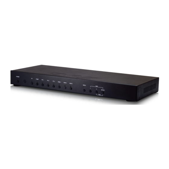
6. oPerAtIoN coNtrolS AND fuNctIoNS 6.1 front Panel 720P ENTER Power Button and leD: Press this button to switch the device on or to set it to standby mode. Once the device is connected to an active power supply the LED will illuminate and the device will switch on automatically. -
Page 9: Rear Panel
6.2 rear Panel IR IN SERVICE INPUT AUDIO RS232 COAX AUDIO CONTROL OUTPUT POWER DC 5V HDMI 1 HDMI 2 PC/HD Cr/Pr Cb/Pb Ir IN: Connect the supplied IR extender to receive the IR signal from the included IR remote. Ensure that the remote is within the direct line-of-sight of the IR extender. -
Page 10: Remote Control
Note: For HDMI signals you can select in the OSD Menu whether you require audio from the HDMI (AUTO) or from the analogue audio inputs (EXT) 4) ycbcr/yPbPr + l/r: Connect to source equipment such as a DVD player for both video and audio signal conversion. 5) cV + l/r: Connect to a composite video source such as a video/ DVD player for both video and audio signal conversion. coNtrol: This port is the link for Telnet or Web GUI controls, connect to an active Ethernet link with an RJ45 terminated cable Power: Switch this power toggle to turn on and activate the device... -
Page 11: Rs-232 Protocols
6.4 rS-232 Protocols Multi-Input Scaler Remote Control Assignment Assignment ► ◄ Baud Rate: 19200bps Data bit: 8 bits Parity: None Flow Control: None Stop Bit: 1... -
Page 12: Rs-232 And Telnet Commands
6.5 rS-232 and telnet commands Command desCription S Power 0/1 0=OFF 1=ON r Power Reports the numeric equivalent for POWER setting (as above) S Source 1~8 1=HDMI 1 5=VIDEO 2=HDMI 2 6=PC 1 3=HDMI 3 7=PC 2 4=YPbPr 8=PC 3 r Source Reports the numerical equivalent for SOURCE setting (as above) - Page 13 Command desCription S coNtrASt 0~60 Sets the numerical equivalent for CONTRAST setting (0~60) r coNtrASt Reports the numerical equivalent for CONTRAST setting S BrIGHtNeSS 0~60 Sets the numerical equivalent for the BRIGHTNESS setting (0~60) r BrIGHtNeSS Reports the numerical equivalent for the BRIGHTNESS setting S Hue 0~60 Sets the numerical equivalent for the HUE...
- Page 14 Command desCription r AuDIo Mute Reports the numeric equivalent for the AUDIO MUTE setting (as above) S HDMI AuDIo 0/1 0=AUTO 1=EXT r HDMI AuDIo Reports the numeric equivalent for HDMI AUDIO setting (as above) S key lock 0/1 0=ENABLE 1=DISABLE r key lock Reports the numeric equivalent for KEY LOCK...
-
Page 15: Osd Menu
6.6 oSD Menu main menu sub menu 3rd menu 4th menu DISPlAy OUTPUT 640×480 60 800×600 60 1024×768 60 1280×768 60 1360×768 60 1280×720 60 1280×800 60 1280×1024 60 1440×900 60 1400×1050 60 1680×1050 60 1600×1200 60 1920×1080 60 1920×1200 60 1280×720P 60* 1920×1080I 60 1920×1080P 60... - Page 16 main menu sub menu 3rd menu 4th menu DISPlAy SIZE OVER SCAN full* FOLLOW INPUT PAN SCAN LETTER BOX UNDER 2 UNDER 1 MODE INFO INfo* INPUT HDCP (HDMI mode only) AUTO SETUP (PC mode only) H_POSITION V_POSITION PHASE CLOCK WXGA/XGA XGA* WXGA...
- Page 17 main menu sub menu 3rd menu 4th menu color CONTRAST 0~60 (30) BRIGHTNESS 0~60 (30) COLOR R 0~1023 (512) G 0~1023 (512) B 0~1023 (512) R OFFSET 0~1023 (512) G OFFSET 0~1023 (512) B OFFSET 0~1023 (512) 0~60 (30) SATURATION 0~60 (30) SHARPNESS 0~30 (0)
- Page 18 main menu sub menu 3rd menu 4th menu AuDIo VOLUME 0~100 (100) off* DELAY 40ms 110ms 150ms SOUND MUTE Auto* SOURCE (HDMI mode only)* EXT. SetuP FACTORY RESET off* KEY LOCK off* POWER SAVE DHcP* IP MODE STATIC SET STATIC IP IP ADDRESS 0.0.0.0.~ 255.255.255.255*...
- Page 19 main menu sub menu 3rd menu 4th menu INforMAtIoN INPUT OUTPUT REVISION IP ADDRESS Note: 1. When the AUDIO SOURCE setting is set to 'AUTO' , the device will send the audio signal according to the input source. If the input signal is HDMI, the device will use the HDMI audio signal and if input is DVI, the device will use the external L/R audio. When AUDIO SOURCE is set to EXT, the device will use the external L/R audio input for the relevant HDMI input only. 2. The Factory reset option in the OSD will only reset part of settings. For a complete reset of the system, please use the reset button on the remote control. 3. 192.168.0.1 (Default Setting). 4. 255.255.255.0 (Default Setting). 5. 192.168.0.254 (Default Setting). 6. Items in BolD with an asterisk (*) are the Factory default settings. Items in brackets are the default values for those settings.
-
Page 20: Telnet Control
6.7 telnet control Before attempting to use the Telnet control, ensure that both the Scaler (via the LAN port) and the PC/Laptop or control system being used are connected to the same active network. To access the Telnet control in Windows 7, click on the "Start" menu and type "cmd"... - Page 21 Type "?" to list all the available commands. Note: All command will not be executed unless followed by a carriage return. Commands are case-insensitive. If the IP is changed then the IP Address required for Telnet access will also needs to be change accordingly.
-
Page 22: Web Gui Control
6.8 web GuI control On a PC/Laptop that is connected to same active network as the Scaler, open a web browser and type device's IP address on the web address entry bar. The browser will bring up the control page of the Scaler. Note: The IP address can be obtained from the OSD menu under Information. -
Page 23: Input Resolution Support
6.9 Input resolution Support Input component HDMI resolution NTSC/PAL 480i/576i 480p/576p 720p@50/60 Hz 1080i@50/60 Hz 1080p@50/60 Hz VGA@60/72/75 Hz SVGA@56/60/72/75 Hz XGA@60/70/75 Hz SXGA@60/75 Hz ... -
Page 24: Output Resolution Support
6.10 output resolution Support output Pc/HD HDMI resolution 480p/576p 720p@50/60 Hz 1080i@50/60 Hz 1080p@50/60 Hz VGA@60 Hz SVGA@60 Hz XGA@60 Hz SXGA@60 Hz UXGA@60 Hz 1280×768@60 Hz ... -
Page 25: Connection Diagram
7. coNNectIoN DIAGrAM Pcs/laptops VGA and Analogue Stereo Inputs AV receiver Smartphone/ tablet device DVD Player coaxial Analogue Digital Stereo Audio Audio component output output and Analogue Modem/ Stereo Inputs router cAt cable rS-232 equipped Pc or control System IR IN SERVICE INPUT AUDIO... -
Page 26: Specifications
8. SPecIfIcAtIoNS Input Ports 3×HDMI, 3×VGA, 1×Component Video, 1×Composite Video, 2×RCA (Analogue Stereo L/R), 6×3.5mm Mini-jack, 1×Extender, 1×USB (Service), 1×RJ45 (Control), 1×RS-232 (Control) output Ports 2×HDMI, 1×VGA/Component Video, 1×Coaxial, 1×3.5mm Mini-jack Input resolution Support Up to UXGA & 1080p output resolution Up to WUXGA (RB) &... -
Page 27: Acronyms
9. AcroNyMS aCronYm CompLete term coMP Component Video Composite Video Red Green Blue Video Graphics Array uXGA Ultra Extended Graphics Array wuXGA Widescreen Ultra Extended Graphics Array... - Page 28 CYP (UK) Ltd., Unit 7, Shepperton Business Park, Govett Avenue, Shepperton, Middlesex, TW17 8BA Tel: +44 (0) 20 3137 9180 | Fax: +44 (0) 20 3137 6279 Email: sales@cypeurope.com www.cypeurope.com v1.02...
Need help?
Do you have a question about the EL-5500 and is the answer not in the manual?
Questions and answers