EOS EmoTouch 3 Installation And Operation Manual
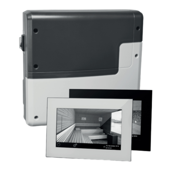
Control unit for sauna and steam room
Hide thumbs
Also See for EmoTouch 3:
- Installation and operation manual (60 pages) ,
- Operating instructions manual (112 pages) ,
- Installation instructions for retailers (72 pages)

Related Manuals for EOS EmoTouch 3


Summary of Contents for EOS EmoTouch 3
- Page 1 I N N O V A T I V E S A U N A T E C H N O L O G Y EmoTouch 3 Control unit for sauna and steam room Installation and operation manual Made in Germany print no.
- Page 2 English Contents Scope of delivery ..............................4 Accessories ................................4 Technical data ............................... 5-6 General information about sauna bathing ....................7 General safety precautions ..........................8 Mechanical installation ............................10 Relay box ..............................10-11 Control panel (recessed installation) ......................12 Temperature sensor installation .......................16 Electrical connections ............................18 Connection of the sauna heater .......................18 Connection of the sauna lighting ......................19...
- Page 3 Service adress .................................54 General Terms and Conditions of Service .....................55...
-
Page 4: Scope Of Delivery
Scope of delivery (changes are reserved) Main electronic unit (with two-part front cover) Control panel with touchscreen display Housing base for flush-mounted installation of the control panel, with mounting brackets De-installation tool (for control panel) Temperature sensor: a) housing, b) sensor board, c) overheat protection fuse, d) 2 mounting screws 4 x 40 mm, e) connection cable 5 m with RJ10 plug, f ) 2-core white cable for over heating protection fuse 5 m Connection cable 5 m (main unit - touch screen display) with RJ14 / RJ10 plugs... -
Page 5: Technische Daten
Technische Daten Voltage (power supply): 400 V 3 N AC 50 Hz Switching capacity: max. 9 kW resistive load, may be extended with a power exten- sion unit (LSG) Heating time limit: 6 h / 12 h / unlimited Housing: plastic, shatter-resistant Display: 7“... - Page 6 ! Sensors and control unit may not be installed in corrosive or highly salty environment. Dimensions main block: H 270 x W 300 x D 100 mm Dimensions control panel: H 142 x W 210 x D 42 mm...
-
Page 7: General Information
General information Dear customer You have purchased a high-quality technical Please check whether the unit has arrived in per- device with which you will have years of sauna fect condition. Any transport damages should be fun. This sauna control unit was designed and immediately reported to the freight forwarder inspected according to the current European delivering the goods or you should contact the... -
Page 8: General Safety Precautions
General safety precautions ature setting. The temperature can be held within operating parameters and a mini- This device can be used by children aged • mal temperature gradient inside the bench 8 upwards and by persons with physical, area of the sauna cabin can be achieved sensory, or mental disabilities, or who only if unit is assembled correctly. - Page 9 When designing the sauna cabin ensure that the external exposed glass surfaces only reach a maximum tempera- ture of 76°C. If necessary, protective fea- tures need to be fitted. ! Attention! Dear customer, according to the valid regulations, the electrical connection of the sauna heater and the control box has to be carried out through the specialist of an authorized electric shop...
-
Page 10: Relay Box
Installation of the main electronic unit The main electronic unit (relay box) may be installed only outside sauna cabin. The recommended places of installation are the outer sauna wall or a plant room (technical room). The installation on the sauna roof is also possible. If empty ducts for connection cable are already available, then they usually predetermine the installation position. - Page 11 Hang the housing on the central upper screw. Make sure that this screw stands out ap- prox. 3 mm from the wall surface. If the connection cables shall be connected from the rear, knock out the corresponding openings in the housing and insert the supplied cable glands (rubber cable holders) into these openings.
-
Page 12: Relay Box
Display panel RJ14 and an extension cable with RJ14 plugs in required length. The coupling The display panel may only be mounted out- and extension cables may be purchased side the cabin. If ductwork is already provided from specialist dealers. for electrical installations then the position of 10. - Page 13 Control panel rear side pull the connection cable as a loop twice through the ring Power adaport jack (by cable length > 25 m) RJ10 RJ14 Ferrite ring holder Ferrite ring with cable loop RJ10 jack (4x) cabin addresses 1-8 mass storage connector type A reset button (for updates)
- Page 14 Display panel installation Wall aperture: Width 188 mm Height 127 mm Depth min. 35 mm alle Maße in mm Notice: Pay attention to the correct ori- entation of the housing base, the opening for connecting cable should be at the bottom side as shown on fig.
- Page 15 Display panel installation Place the control panel directly in front of the housing base and pay attention to the correct ori- entation - the cable connector shall be at the bottom and the SD card slot at the top. Plug in the connection cable with RJ10 plug which you pulled through the housing base.
- Page 16 Connection of sensor cables Do not lay sensor and power supply lines together, or lead them through the same duct. This can lead to interferences in the electronics, such as “fluttering” in the relays. Connect the cable shield- ing (if present) to ground in the control unit. Please observe that the following dimensions relate to the values stipulated during the unit in- spection acc.
-
Page 17: Installation Overview
Lead the sensor cable (red) and the limiter cable (white) through the drilled hole and connect both cables to the main relay box as advised on pages 18-19. Connect the sensor cable to the sensor board according to fig. Make sure the connections are correct. -
Page 18: Electrical Connections
Electrical connection Sauna heater connection The electrical connections may only be car- ried out by a certified electrician in compli- ance with the guidelines of the local power Install the sauna heater and the vaporizer (if supply company and applicable legal regu- available) inside the sauna cabin in front of the lations (e.g. - Page 19 Sauna lamp connection Heating time limitation The maximal heating time may be limited with the jumper #5 on the main board of the relay The sauna lamp must have the protection box. The limitation may be set to 6 hours, 12 class of at least IPx4 and should be resistant to hours or to unlimited.
-
Page 20: Terminal Layout
Connection diagram EmoTouch II+/3 Feuchtefühler Steckeranschluß Fühler humidity sensor Sensor plug connector Bankfühler/2nd Sensor Ofenfühler/Sensor reserviert Leistungsteil Sensorbus Main unit (relay box) Relais box Saunabus light S1 S1 N L1 L2 L3 N W V U N L N L N Leuchte/light Lüfter/fan Bedienteil Control panel... -
Page 21: Temperature Sensor
Temperature sensor ! ATTENTION! Feuchtefühler Humidity sensor Bankfühler If a sensor is plugged into the sauna bus 2nd sensor Ofenfühler reserviert (RJ14 connector), the sensor and the Main sensor reserved main board may be irreparably damaged! Sensorbus RJ 10 The sensor cable with RJ10 plugs shall be con- nected to one of three sensor bus RJ10 jacks on Saunabus the board. - Page 22 Installation of the The sensor symbol will be displayed either on the start screen (Emotec, EmoStyle models) or optional 2nd sensor in the temperature query submenu (EmoTouch models). If the 2nd sensor is faulty the temperature will Place of installation: The 2nd sensor (bench be controlled via the main sensor over the sensor) shall be mounted on the ceiling over heater.
- Page 23 Humidity Feuchtefühler Humidity sensor Bankfühler sensor installation 2nd sensor Ofenfühler reserviert Main sensor reserved Sensorbus RJ 10 1. The humidity sensor shall be mounted in the Connection over- middle of the wall opposite to the heater at view for tempera- Saunabus ture sensor, bench approx.
- Page 24 Make sure to use the appropriate heat-resistant silicone cable with min. 1,5 mm² cross section for vaporizer connection. EOS control units will detect water shortage if there is zero potential at the Wm terminal of the control unit. Pay attention to the maximum switching pow- er of the control unit vaporizer output.
- Page 25 Commissioning (initial setup) Setup after initial start or after a reset The EmoTouch 3 control unit allows fast and intuitive configuration in several steps by commis- sioning during the first start or after a system reset. Select language Einstellungen Settings...
- Page 26 Select between private or commercial use Select the applicable option and touch it again to confirm: for private use, or for commercial use Safety system for saunas as per norm EU 60335 available? Select the applicable option and touch it again to confirm: - yes or - no.
- Page 27 Control of several cabins from one display panel In order to control several cabins from one display panels these cabins should be connected and properly configured. Please refer to the chapter „multi-cabin connection“ for more details. After you have assigned the correct cabin address (ID) to each cabin the symbol of mult-cabin operation as shown below will appear in the bottom line of the display: The number in this symbol is the number of the currently selected cabin.
- Page 28 Multi-cabin connection and configuration The EmoTouch 3 control unit allows to control up to 8 separate cabins from one display panel. These can be saunas, steam rooms or hammams. The connection is made to the 4 connectors (ports) on the rear side of the display panel (see picture below).
- Page 29 On the page 37 you will find the connection overview with the example of connections for 8 cabins (mixed saunas and steam rooms). Programming of the cabin address (ID). The relay box of the sauna control unit or the main board of the generator are shipped from fac- tory with the default cabin address #1.
- Page 30 Example - connection of 8 cabins to the EmoTouch 3 control panel EmoTouch 3 Bedienteil Display panel Tableau de commande max. max. max. max. SAUNA SAUNA 9 kW 3 kW 3 kW 9 kW Saunaofen Verdampfer Verdampfer Saunaofen Sauna heater...
- Page 31 Operation interface by multi-cabin control By several cabins connected to the control panel (providing they have been connected and programmed correctly) the multi-cab- in control symbol will appear on the display in the bottom line: 31. Oktober 2016 14:22:38 Example: Sauna cabin The number inside this symbol indicates the number of the currently selected cabin.
-
Page 32: Extended Settings
Operation Control panel - graphic user interface (GUI) Light Climate Colour light for dimming check (optional) touch 3 sec Sound Temperature to make settings touch the heater >3 sec Sate and Time 31. November 2016 Cabin selection 14:22:38 (by multiple cabins) On/Off Fault touch >3 sec to... -
Page 33: Extended Settings
Method of operating the graphic user interface Briefly touch to select or enable any of the functions available on the graphical user interface (cab- in icon). Keep touching a function (>3 sec) to access the associated settings screen. For safety reasons, you should always press certain symbols icons for more than 3 sec (e.g. - Page 34 Make sure to remember the selected pin code! Please bear in mind that in the case this code is lost you will not be able to operate the control unit. In the case the pin code is no longer available and cannot be restored please contact your local EOS dealer or EOS service.
- Page 35 Graphic user interface GUI and climate conditions check Thanks to the modern GUI you can quickly access all functions and make necessary settings, as well as make a simple instant query for the current climate condition. The symbols on the start screen may be displayed in different colours, in order to indicate the current operation status - e.g.
- Page 36 Operation and program settings Switching the heating On / Off Press the symbol for approx. 3 seconds. The heating will switch on and the display will show the active heating mode (see example on page 29). The light will be also switched on. To switch the sauna off, touch shortly the symbol again.
- Page 37 and under the curve may be selected. For instance at 60°C temperature your can set up to 40% rel. air humidity. In order to set a higher humidity you will need first to reduce the temperature. If the sauna has been used in dry mode with high temperatures and you switch to the humid mode, the vaporizer will start to work only after the temperature drops under the max.
- Page 38 ! Attention! This function is only allowed to be used if your sauna is fitted with an ap- proved safety system, which prevents the heater from being switched on in unsafe condition (e.g. a towel forgotten on the heater). Even in the case if your sauna has such an approved system, prove there are no objects forgotten on the heater.
- Page 39 For every switching you can set an individual temperature. Briefly touch a program (1 - 4), start with 1 if there are no settings yet on this day. • Set the Start time in hours and minutes using +/- buttons - e.g. 9:30. •...
- Page 40 Extended settings Settings By private use touch briefly the symbol to display the Extended Settings menu. By commercial use press >3 sec on this symbol 5645 and give in the access code to open the Extended Settings menu. By multi-cabin control - this menu must be opened from the Cabin Overview interface.
- Page 41 Make sure to remember the selected pin code! Please bear in mind that in the case this code is lost you will not be able to operate the control unit. In the case the pin code is no longer available and cannot be restored please contact your local EOS dealer or EOS service.
- Page 42 Make sure to remember the selected pin code! Please bear in mind that in the case this code is lost you will not be able to operate the control unit. In the case the pin code is no longer available and cannot be restored please contact your local EOS dealer or EOS service.
- Page 43 Potential-free contact PFC (volt-free contact / floating contact) The PFC function allows you to switch some external equipment with the special switch shown on the main cabin interface. For instance the additional light circuit, music or others. To make the “on” or “off” switching touch briefly the symbol on the main cabin interface.
- Page 44 Service and setup settings The EmoTouch 3 provides an extensive set of features and tools to setup and optimize the opera- tion. This setup menu is protected with a PIN code and should not be accessible to the end users.
-
Page 45: Firmware Update
Symbol overview Refilling time Service / maintenance intervals Choose to set the service/maintenance intervals Grace time to refill the vaporizer after water shortage alarm. Only for Bi-O heaters. Firmware Update Afterheating time Firmware update possibility for display panel, Duration of the „sauna dry“ program after humid operation. - Page 46 Firmware update Here you can conduct the firmware update. For the update you will need an empty mass storage device with the standard type A connector. • Download the firmware from www.eos-sauna.de/ Massenspeicher- anschluss service-support/software and unzip the ZIP file to your mass storage device.
- Page 47 In the case of power supply loss the control panel will attempt to resume the update process. If the display panel does not start or shows a boot load error press firmly on the “reset” button on the board next to the battery cell. The unit will reboot and offer update options dialogue, allowing you to attempt to repeat the update.
- Page 48 Maximum load allowed for this output: • resistive load / alternating current: max. 250V AC / 10A • inductive load / alternating current 500VA • direct current: • Up to 30V DC max. 16A (480 W) • Up to 110V DC max. 0,3A (33W) •...
- Page 49 > 50° Switching „on“ if the current temperature reaches 50°C. < 50° Switching „off“ if the current temperature reaches 50°C. Switching „on“ if the cabin is on. Switching „off“ if the cabin is on. Disable volt-free output (the contact symbol will disappear on the screen, output not ac- tive).
- Page 50 Refilling time Here you can set the grace time which the end user has to refill the vaporizer after the water short- age alarm. If the vaporizer has not been refilled within this time, it will be switched off (overheating protection).
-
Page 51: Troubleshooting
Troubleshooting (error messages) EmoTouch 3 is able to detect various faults and operation states and to show them on the display as symbol or text messages. By only one connected cabin the messages will be shown directly on the display on top of the current interface. By multiple cabins if you are in the... -
Page 52: Recycling
Recycling The devices which are no longer needed have to be recycled in accordance with the EU-guideline 2002/96/EG or ElektroG or the applicable national legal regulations. Do not dispose off with the household garbage! - Page 53 The device „Switch-off“ switch The control unit is equipped with a “Switch-off” rocker switch. You will find this switch on the top side of the housing by Econ series control units and on the left side of the main relay box by control units of Emotec, EmoStyle and EmoTouch series.
- Page 54 Service Address: EOS Saunatechnik GmbH Schneiderstriesch 1 35759 Driedorf, Germany Tel: +49 (0)2775 82-514 Fax: +49 (0)2775 82-431 servicecenter@eos-sauna.de www.eos-sauna.de Equipment commissioning date: Please keep this address in a safe place togeth- er with the installation guide. Stamp and signature of the authorized elec-...
- Page 55 General Terms and Conditions of Service shipments via parcel post. The manufacturer shall accept no liability for damage incurred as a result of improper I. Scope packaging in an individual shipment. Unless otherwise agreed in writing in a specific case, VI.
Need help?
Do you have a question about the EmoTouch 3 and is the answer not in the manual?
Questions and answers