
Subscribe to Our Youtube Channel
Related Manuals for Alfa IN aXe 200 IN PFC


Summary of Contents for Alfa IN aXe 200 IN PFC
-
Page 1: Welding Machine
WELDING MACHINE aXe 200 IN PFC OPERATING MANUAL ALFA IN a.s. © www.alfain.eu aXe 200 IN PFC manual EN 03... -
Page 2: Table Of Contents
OPERATOR CONTROLS ................9 GETTING STARTED MIG/MAG .............. 14 GETTING STARTED TIG ................ 20 GETTING STARTED MMA ..............22 ROUTINE MAINTENANCE & INSPECTION ..........22 10. STATEMENT OF WARRANTY .............. 23 11. DISPOSAL ..................... 24 ALFA IN a.s. © www.alfain.eu... -
Page 3: Introduction
3/24 1. INTRODUCTION Congratulations on your new ALFA IN product. We are proud to have you as our customer and will strive to provide you with the best service and reliability in the industry. This Operating Manual has been designed to instruct you on the correct use and operation of your ALFA IN product. -
Page 4: Safety Instructions And Warnings
16. The operator must ensure all flammable materials are removed from the work area to avoid any risk of fire. 17. The operator must NEVER weld containers that have previously contained petrol, lubricants, gas or similar flammable materials, even if the container ALFA IN a.s. © www.alfain.eu... - Page 5 (for example open circuit, short circuit or lack of power), the permitted values cannot be exceeded. The welding machines of this type can be marked with the ALFA IN a.s. © www.alfain.eu...
- Page 6 During operation, the device may be the source of interference. Caution We warn users, that they are responsible for possible interference from welding. ALFA IN a.s. © www.alfain.eu...
-
Page 7: Technical Data
Spool diameter Spool weight 4. EQUIPMENT PART OF DELIVERY Item No. Description 5.0286 aXe 200 IN PFC VM0321-2 Hose Gas 3m Pegas quick connector G1/4 VM0023 Earthing Cable 3 m 400 A 35mm2 35-50 K910-1 Adapter up to 18 kg ACCESSORIES TO ORDER Item No. - Page 8 Pressure Reducer BASECONTROL Ar 2 manometers 6125 Pressure Reducer BASECONTROL CO2 2 manometers S777a Welding Helmet ALFA IN S777a Black 4488 Wire 0.8 Coreshield 15 A D200 Self Shielding 4,5kg spool 6050 Set for Aluminium with roll AL 22/30 0,8-1,0...
-
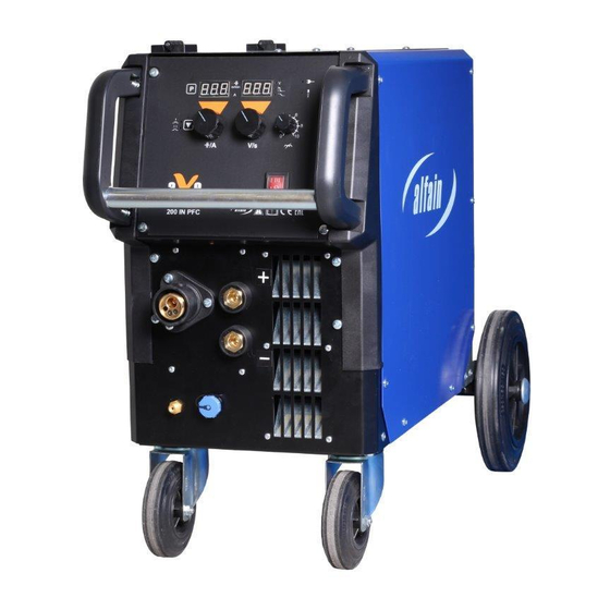
Page 9: Operator Controls
9/24 5. OPERATOR CONTROLS MAIN PARTS OF THE MACHINE Fig. Main parts of the machine ALFA IN a.s. © www.alfain.eu... - Page 10 EURO connector EURO connector male Torch Quick connector male Earthing clamps Quick connector (+) Quick connector (-) Gas bottle Cylinder valve Pressure reducer High pressure manometer Low pressure manometer Adjusting screw Gas outlet Soneloid valve Chain ALFA IN a.s. © www.alfain.eu...
- Page 11 Button: method selection (MIG/MAG, MMA, TIG) Display LED. If it lights, on the left display is shown welding current in A. LED. If it lights, on the left display is shown wire feed speed in m/min. Display ALFA IN a.s. © www.alfain.eu...
- Page 12 OFF – of the remote control Switch Spool Gun. In the ON position one can weld with the Spool Potentiometer for the BURNBACK time setting Potentiometer for the initial wire speed setting Potentiometer for the PRE GAS time setting ALFA IN a.s. © www.alfain.eu...
- Page 13 13/24 Potentiometer for the POST GAS time setting Gas setting button Wire feeding button WIRE FEEDER Fig. 4. Wire feeder Pos. Description Nut of pressure arm Pressure arms Inlet liner EURO connector Roll ALFA IN a.s. © www.alfain.eu...
-
Page 14: Getting Started Mig/Mag
Getting started must be consistent with technical data and conditions of use. CHOOSING THE FEEDING ROLL In all machines (ALFA IN MIG / MAG) rolls with two grooves are used. These grooves are intended for two different wire diameters (e.g. 0,8 and 1,0 mm). - Page 15 By means of the button V2 select 2T or 4T, appropriate LED V1 or V3 will light. Press the button 39 in the space of the wire feeder. The welding wire is fed into the torch. After coming off from the torch tube, screw the current ALFA IN a.s. © www.alfain.eu...
- Page 16 4. After long-term shutdown of the machine or replacement of the torch it is suitable to blow the pipes with protective gas before welding. Fig. 7. Gas flow setting Pos. Description Gas bottle Cylinder Valve Pressure Reducer High Pressure Manometer Low Pressure Manometer Adjusting Screw Gas outlet ALFA IN a.s. © www.alfain.eu...
- Page 17 ADJUSTING WELDING PARAMETERS FOR MIG MAN 1. Approximate setting for the MIG / MAG welding current and voltage corresponds the empirical relationship U2 = 14 +0.05 I . According to this ALFA IN a.s. © www.alfain.eu...
- Page 18 Table of approximate parameter settings ADJUSTING THE MACHINE FOR ANOTHER WIRE DIAMETER In all machines ALFA IN MIG / MAG are used rolls with two grooves. These grooves are intended for two different wire diameters (e.g. 0,8 a 1,0 mm). Groove can be replaced by removing the rolls and rotating them, or use a different roll grooves with required dimensions.
- Page 19 Description Upper terminal (+) Bridge Middle terminal Lower terminal (-) ADJUSTING THE MACHINE FOR WELDING OF ALUMINIUM For feeding the AL wire it is necessary to use roll with the “U” profile - see paragraph ALFA IN a.s. © www.alfain.eu...
-
Page 20: Getting Started Tig
3. Connect the machine to power supply and turn the main switch A1 on the front panel to ON. Connect gas hose and gas flow adjustment described in ADJUSTMENT OF GAS FLOW. 5. Press the button V5 and by means of the encoder V15 choose the program number 3. ALFA IN a.s. © www.alfain.eu... - Page 21 8. By means of the encoder V15 you can set the time of DOWN SLOPE. 9. By means of the potentiometers 36 and 37 you can change the time of PRE GAS or POST GAS. ALFA IN a.s. © www.alfain.eu...
-
Page 22: Getting Started Mma
The welder should also be wiped clean. If necessary, solvents that are recommended for cleaning electrical apparatus may be used. 6. Troubleshooting and repairing of AXE welding equipment should only be ALFA IN a.s. © www.alfain.eu... -
Page 23: Statement Of Warranty
3. ALFA IN will repair or replace, at its discretion, any warranted parts or components that fail due to defects in material or workmanship within the warranty period. -
Page 24: Disposal
In accordance with European Council Directive 2002/96/EC on electrical electronic equipment waste implementation in accordance with national law, electric tools that have reached the end of their service life must be collected separately and returned to an environmentally compatible recycling facility. ALFA IN a.s. © www.alfain.eu...
Need help?
Do you have a question about the aXe 200 IN PFC and is the answer not in the manual?
Questions and answers