
Related Manuals for Alfa IN PERUN 200 MIG MAN PFC


Summary of Contents for Alfa IN PERUN 200 MIG MAN PFC
- Page 1 WELDING MACHINE PERUN 200 MIG MAN PFC OPERATING MANUAL ALFA IN a.s. © www.alfain.eu PERUN 200 MIG MAN PFC manual EN 02...
-
Page 2: Table Of Contents
GETTING STARTED MIG/MAG .............. 14 GETTING STARTED TIG ................ 20 GETTING STARTED MMA ..............22 10. ROUTINE MAINTENANCE & INSPECTION .......... 22 11. STATEMENT OF WARRANTY .............. 23 12. DISPOSAL ..................... 23 13. WARRANTY LIST .................. 24 ALFA IN a.s. © www.alfain.eu... -
Page 3: Introduction
3/24 1. INTRODUCTION Congratulations on your new ALFA IN product. We are proud to have you as our customer and will strive to provide you with the best service and reliability in the industry. This Operating Manual has been designed to instruct you on the correct use and operation of your ALFA IN product. -
Page 4: Safety Precautions
CSN 07 83 05. 3. The welder must use protective equipment. 4. Before working on the electrical part, removing the cover or cleaning it is necessary to disconnect the device from the network. ALFA IN a.s. © www.alfain.eu... -
Page 5: Operating Conditions
For maintenance and repair, use only original spare parts from ALFA IN. 2. Device complies with IEC 61000-3-12. 3. The welding machine is tested according to the degree of protection IP 23S, which provides protection against the intrusion of solid bodies with a diameter greater than 12 mm and protection against ingress of water, falling on the machine in a vertical direction or max degree of 60°. -
Page 6: Technical Data
Spool diameter Spool weight ALFA IN continuously strives to produce the best product possible and therefore reserves the right to change, improve or revise the specifications or design of this or any product without prior notice. Such updates or changes do not entitle the buyer of equipment previously sold or shipped to the corresponding changes, updates, improvements or replacement of such items. -
Page 7: Equipment
7/24 5. EQUIPMENT CONTENT OF DELIVERY Item No. Description 5.0292 PERUN 200 MIG MAN PFC ACCESSORIES TO ORDER Item No. Description Picture Torch PARKER SGB 250 3m SGB25-3 (MIG/MAG) Torch PARKER SGB 250 4m SGB25-4 (MIG/MAG) Torch PARKER SGB 250 5m... - Page 8 Small Gas Lens Body Starter SGL2 Kit 1.6mm-1/16" Small Gas Lens Body Starter SGL4 Kit 2.4mm-3/32" Small Gas Lens Body Starter SGL5 Kit 3.2mm-1/8" 700.0306.10 Electrode wolf.1.6x175-Violet 700.0308.10 Electrode wolf.2.4x175-Violet Electrode wolfram E3 700.0310.10 3.2x175 - violet ALFA IN a.s. © www.alfain.eu...
-
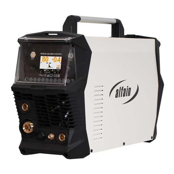
Page 9: Operator Controls
9/24 6. OPERATOR CONTROLS Fig. 1. PERUN 200 MIG MAN PFC Pos. Description Control panel Quick connector (+) of welding cables ALFA IN a.s. © www.alfain.eu... - Page 10 CONTROL PANEL Fig. 2. Control panel Pos. Descriptions LED. If it lights the method MIG/MAG has been selected by the button V19. LED. If it lights the method MMA has been selected by the button V19. ALFA IN a.s. © www.alfain.eu...
- Page 11 Right display LED. If it lights the display V18 shows the wire feed speed in m/min. LED. If it lights the display V18 shows welding current in A. Left display Button for selecting the welding method. ALFA IN a.s. © www.alfain.eu...
- Page 12 Spool Gun Potentiometer for the Burnback time setting Potentiometer for the initial wire speed setting Potentiometer for the Pre Gas time setting Potentiometer for the Post Gas time setting Gas setting button Wire feeding button ALFA IN a.s. © www.alfain.eu...
- Page 13 Roll OVERVIEW OF ROLLS FOR WIRE FEED a = 22 mm b = 30 mm Groove type Wire diameter Item No 0,6-0,8 2187 Steel 0,8-1,0 2188 0,8-1,0 2270 Aluminum 0,8-1,0 2318 Flux core 1,0-1,2 2319 ALFA IN a.s. © www.alfain.eu...
-
Page 14: Getting Started Mig/Mag
Getting started must be consistent with technical data and conditions of use. CHOOSING THE FEEDING ROLL In all machines (ALFA IN MIG / MAG) rolls with two grooves are used. These grooves are intended for two different wire diameters (e.g. 0,8 and 1,0 mm). - Page 15 7. Turn the main switch on the back panel to ON. 8. Press the button V19 to select the mode MIG/MAG . LED V1 lights up. 9. Press the button V4 to select 2T or 4T. The corresponding LED V5 or V6 ALFA IN a.s. © www.alfain.eu...
- Page 16 4. After long-term shutdown of the machine or replacement of the torch it is suitable to blow the pipes with protective gas before welding. Fig. 8. Gas flow setting Pos. Description Gas bottle Cylinder Valve Pressure Reducer High Pressure Manometer Low Pressure Manometer Adjusting Screw Gas outlet ALFA IN a.s. © www.alfain.eu...
- Page 17 Table of approximate parameter settings ADJUSTING THE MACHINE FOR ANOTHER WIRE DIAMETER In all machines ALFA IN MIG / MAG are used rolls with two grooves. These grooves are intended for two different wire diameters (e.g. 0,8 a 1,0 mm). Groove can be replaced by removing the rolls and rotating them, or use a different roll grooves with required dimensions.
- Page 18 In case that you want to weld with a flux core wire, it is necessary to remove the gas nozzle from the torch before you start welding. During the welding process, you must not touch the weldment with the contact tip. There would be a risk of wire baking. ALFA IN a.s. © www.alfain.eu...
- Page 19 Fig. 10. Customization of the feed for the aluminium wire Pos. Description EURO connector Rolls Liner terminal for 4,0mm, 4,7mm outer diameter O-ring 3,5 x1, 5mm to prevent escape of gas Liner tefl. Sustain pipe for teflon and plastic liner ALFA IN a.s. © www.alfain.eu...
-
Page 20: Getting Started Tig
5737 CONNECTOR ST 12 PIN MALE FOOT SPOOL TIG TORCH MIG TORCH PEDAL SPOOL SPOOL GUN SPOOL GUN POTENTIOMETER POTENTIOMETER SPOOL CENTER TAP POTENTIOMETER POTENTIOMETER POTENTIOMETER SIGNAL POTENTIOMETER START/STOP START/STOP START/STOP START/STOP (GND) (GND) SPARE LINE ALFA IN a.s. © www.alfain.eu... - Page 21 By means of the potentiometer V7 adjust the welding current. By means of the potentiometer adjust the time of Down Slope. 8. By means of the potentiometer 36 you can change the time of Gas. ALFA IN a.s. © www.alfain.eu...
-
Page 22: Getting Started Mma
7. The person carrying out the servicing needs and repairs must know what to look at, what to look for and what to do. ALFA IN a.s. © www.alfain.eu... -
Page 23: Statement Of Warranty
3. ALFA IN will repair or replace, at its discretion, any warranted parts or components that fail due to defects in material or workmanship within the warranty period. -
Page 24: Warranty List
As a warranty list serves proof of purchase (invoice) on which is the serial number of the machine, eventually a warranty list below, which is filled in by an authorized dealer. Serial number: Day, month (written in words) and year of sale: Stamp and dealer signature: ALFA IN a.s. © www.alfain.eu...
Need help?
Do you have a question about the PERUN 200 MIG MAN PFC and is the answer not in the manual?
Questions and answers