Alfa IN PEGAS 200 AC/DC PULSE Smart Operating Manual
Welding inverter
Hide thumbs
Also See for PEGAS 200 AC/DC PULSE Smart:
- Operating manual (16 pages) ,
- Operating manual (16 pages)

Related Manuals for Alfa IN PEGAS 200 AC/DC PULSE Smart


Summary of Contents for Alfa IN PEGAS 200 AC/DC PULSE Smart
- Page 1 WELDING INVERTER PEGAS 200 AC/DC PULSE Smart PEGAS 200 AC/DC Smart OPERATING MANUAL ALFA IN a.s. © www.alfain.eu PEGAS 200 AC-DC (Pulse) Smart manual ENG 03...
-
Page 2: Table Of Contents
TWO STROKE AND FOUR STROKE IN TIG MODE ....... 15 BASIC SETTINGS FOR TIG WELDING ..........16 GENERAL INFORMATION ON THE WELDING MODES ......17 10 ROUTINE MAINTENANCE & INSPECTION ..........18 11 STATEMENT OF WARRANTY ..............19 12 DISPOSAL ....................19 ALFA IN a.s. © www.alfain.eu... -
Page 3: Introduction
3/19 1 INTRODUCTION Congratulations on your new ALFA IN product. We are proud to have you as our customer and will strive to provide you with the best service and reliability in the industry. This Operating Manual has been designed to instruct you on the correct use and operation of your ALFA IN product. -
Page 4: Safety Instructions And Warnings
THERE IS A VERY HIGH RISK OF EXPLOSION. The operator must be aware of all the special regulations which he needs to conform to when welding in enclosed spaces with a high risk of ALFA IN a.s. © www.alfain.eu... - Page 5 (PCC) must be least 4499 kW. User is obliged to consult with the electricity supplier if the impedance of the network at this point is that required short-circuit capacity Z = 36 mΩ and ALFA IN a.s. © www.alfain.eu...
-
Page 6: Technical Data
32 A with the maximum permissible fuse of 25 A. The corresponding data for such a 32 A plug are stated in the table above in brackets. ALFA IN a.s. © www.alfain.eu... -
Page 7: Equipment
25 A. Attention! Do not connect to the interconnected voltage (delta voltage) (between 2 phases)! Replacement of the plug may only be performed by ALFA IN authorized service personnel. ALFA IN continuously strives to produce the best product possible and therefore reserves the right to change, improve or revise the specifications or design of this or any product without prior notice. -
Page 8: Operator Controls
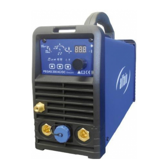
5 OPERATOR CONTROLS MAIN PARTS Fig . 1 Main parts Pos. Description Operating panel Quick connector + Gas connector of the welding torch Torch control connector Quick connector - ON/OFF switch Gas inlet Mains cable and plug ALFA IN a.s. © www.alfain.eu... - Page 9 9/19 OPERATING PANEL Fig. 2 PEGAS 200 AC/DC Pulse Smart Fig. 3 PEGAS 200 AC/DC Smart Pos. Description LED MMA LED TIG LA – Lift Arc ignition Button switch MMA/TIG HF/TIG LIFT ARC. LED HF. If illuminated the HF ignition was set.
- Page 10 LED welding current MMA 10 – 170 A, just for MMA. LED lights up after pressing the encoder 11. LED ARC FORCE just for MMA, 0 – 100. LED lights up after pressing the encoder 11. ALFA IN a.s. © www.alfain.eu...
-
Page 11: Getting Started
Prevent touching the electrode any metal material for in this mode the terminals A2 and A5 are under current. 8. Insert the coated electrode into the electrode holder, connect the clamps of the ground cable to the welding piece and you may start welding. ALFA IN a.s. © www.alfain.eu... - Page 12 9. The corresponding LED will light up. Select the method desired DC or AC method by means of the button 5. The corresponding LED will light up. In the welding torch must be installed a corresponding tungsten ALFA IN a.s. © www.alfain.eu...
- Page 13 The following table describes the influence setting the clearance effect. Clearance effect Value -5 to 0 Value +1 to +5 Shape of the current curve Penetration Deep Shallow Level of wear of the of Smaller Bigger tungsten electrode ALFA IN a.s. © www.alfain.eu...
- Page 14 To reach the maximal current, set by encoder 11, requires to gently pressing to the lowest position of the stepping surface P1. The set current will be displayed on the display 31. 5. The welding process ends after releasing the stepping surface P1. ALFA IN a.s. © www.alfain.eu...
-
Page 15: Two Stroke And Four Stroke In Tig Mode
15/19 7 TWO STROKE AND FOUR STROKE IN TIG MODE TWO STROKE – 2T Welding current Down slope Current Postgas Pregas FOUR STROKE – 4T Welding current Down slope Up slope Current Post Pregas ALFA IN a.s. © www.alfain.eu... -
Page 16: Basic Settings For Tig Welding
8-12 8-12 150-180 8-12 8-12 180-200 10-15 8-12 180-240 10-15 10-12 Table for Cuprum, DC current Material Tungsten Filler Welding Argon thickness electrode material current flow nozzle heating diameter diameter l/min °C 70-80 120-140 130-160 ALFA IN a.s. © www.alfain.eu... -
Page 17: General Information On The Welding Modes
To completely prevent the tungsten being included, you must not let the electrode touch the piece to be welded. However you use a start-up with high frequency (HF) discharge, that allows striking of the electric arc at a distance. ALFA IN a.s. © www.alfain.eu... -
Page 18: Routine Maintenance & Inspection
6. The person carrying out the servicing needs and repairs must know what to look at, what to look for and what to do. ALFA IN a.s. © www.alfain.eu... -
Page 19: Statement Of Warranty
3. ALFA IN will repair or replace, at its discretion, any warranted parts or components that fail due to defects in material or workmanship within the warranty period.
Need help?
Do you have a question about the PEGAS 200 AC/DC PULSE Smart and is the answer not in the manual?
Questions and answers