
Related Manuals for Alfa IN aXe 250 PULSE Smart (AL)GAS


Summary of Contents for Alfa IN aXe 250 PULSE Smart (AL)GAS
- Page 1 WELDING MACHINES aXe 250 PULSE Smart (AL) aXe 320 PULSE Smart (AL) GAS / H aXe 250 Smart GAS aXe 320 Smart GAS / H INSTRUCTION MANUAL ALFA IN a.s. © www.alfain.eu aXe 250-320 PULSE smart (AL) manual EN 04...
- Page 2 8. MIG/MAG WELDING SYNERGY ................24 9. PULSED MODE ....................25 10. MIG/MAG WELDING MANUAL ................26 11. MMA WELDING (COATED ELECTRODE- ELE) ............27 12. ROUTINE MAINTENANCE & INSPECTION ............28 13. DISPOSAL ......................31 ALFA IN a.s. © www.alfain.eu...
-
Page 3: Introduction
3/31 1. INTRODUCTION Dear Consumers! Company ALFA IN a.s. thanks you for buying our product and believe that you will be satisfied with our machine. Welding machines aXe 250 PULSE smart (AL) GAS and aXe 320 PULSE smart (AL) GAS/H O are IGBT invertors. -
Page 4: Safety Precautions
ČSN 07 85 09. 3. The welder must use protective equipment. 4. Before working on the electrical part, removing the cover or cleaning it is necessary to disconnect the device from the network. ALFA IN a.s. © www.alfain.eu... -
Page 5: Operating Conditions
The manufacturer is not liable for damages resulting from improper use or handling. For maintenance and repair, use only original spare parts from ALFA IN. 2. Device complies with IEC 61000-3-12 with following conditions:... -
Page 6: Technical Data
IP 23S Standards EN 60974-1, EN 60974-10 cl. A Dimensions (w x l x h) generator 474 x 911 x 670 Weight - generator /compact 47,6 Wire speed m/min 1,0 - 20,0 Spool diameter Spool weight ALFA IN a.s. © www.alfain.eu... - Page 7 The machine structure is designed so that, in any case, even if the failure rectifier does not exceed the permitted peak value of the open circuit voltage according to EN 60974-1, i.e., 113 V direct current or 68 V alternating. ALFA IN a.s. © www.alfain.eu...
-
Page 8: Accessories
If you decide to use a different torch than the above, it is necessary to choose one, according to your current range and load time of the torch. ALFA IN a.s. is not liable for damage caused by overload welding torches. -
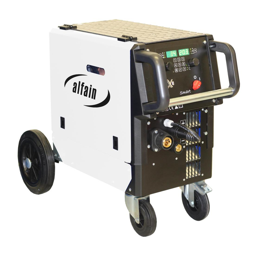
Page 9: Description Of The Appliance
9/31 6. DESCRIPTION OF THE APPLIANCE MAIN PARTS Fig. 1 – Main parts of the machine ALFA IN a.s. © www.alfain.eu... - Page 10 10/31 Fig. 2 – Main parts of the machine with cooling unit ALFA IN a.s. © www.alfain.eu...
- Page 11 High pressure manometer Low pressure manometer Adjusting Screw Gas outlet Soneloid valve Chain NOTICE If the machine is equipped with the connector A11, the machine can be controlled in MMA method by the remote control. ALFA IN a.s. © www.alfain.eu...
- Page 12 Roll CHOOSING THE FEEDING ROLL In all machines ALFA IN MIG / MAG rolls with two grooves are used. These grooves are intended for two different wire diameters (e.g. 0,8 and 1,0 mm). Rolls for wire feed must comply with the diameter and material of the welding wire.
- Page 13 4305 ADJUSTING THE MACHINE FOR ANOTHER WIRE DIAMETER In all machines ALFA IN MIG / MAG are used rolls with two grooves. These grooves are intended for two different wire diameters (e.g. 0,8 a 1,0 mm). Groove can be replaced by removing the rolls and rotating them, or use a different roll grooves with required dimensions.
- Page 14 D1 so that while stopping the feed, spool will be stopped on time (it will avoid excessive release of wire). However, too tight brake needlessly strains the feeding mechanism and thus slippage ALFA IN a.s. © www.alfain.eu...
- Page 15 The welding wire is fed into the torch. After coming off from the torch tube, screw the current nozzle and gas nozzle on. 9. Before welding, spray the area in a gas hose and current nozzle with a separation spray, to prevent damage. ALFA IN a.s. © www.alfain.eu...
- Page 16 4. After long-term shutdown of the machine or replacement of the torch it is suitable to blow the pipes with protective gas before welding. Fig. 2 – Gas flow setting Pos. Description Gas bottle Cylinder Valve Pressure Reducer High Pressure Manometer Low Pressure Manometer Adjusting Screw Gas outlet ALFA IN a.s. © www.alfain.eu...
-
Page 17: Basic Settings
3. Speed of the wire 4. Material thickness 5. Sign of the secondary parameter Right display shows: 1. Welding voltage 2. Correction 3. Choke LED - Voltage or voltage correction Button for selecting the parameters to be displayed ALFA IN a.s. © www.alfain.eu... - Page 18 2. Selects the synergic curve (program number) using the encoder V16 according to the table, which is located inside. To confirm the program number press the encoder V5. 3. If you press any button other than V5, or after 10 s, you exit the menu. ALFA IN a.s. © www.alfain.eu...
- Page 19 , 4T . The two stroke mode is signalized by LED V17. First tact: press and hold the torch button, the machine will start welding. Second tact: release the torch button, the machine will stop welding. ALFA IN a.s. © www.alfain.eu...
- Page 20 BILEVEL BCU ≠ 100 % The difference of BILEVEL compared with classical stairs is in the second tact. When you quickly press and release the torch button, the machine switches between two set main welding currents. ALFA IN a.s. © www.alfain.eu...
- Page 21 3. Press the encoder V5 to confirm the change. 4. Press any button, or after 10 s, to exit the menu without saving changes. 5. Secondary parameters are common for methods manual and synergy. Synergy method allows to set more secondary parameters. ALFA IN a.s. © www.alfain.eu...
- Page 22 By long-pressing the button V4 (1) perform the display test. By long-pressing the button V4 (2) display the machine variant / roll size (only for machines with speed measurement) (37 – AXE 250/320 PULSE SMART, 30 – AXE 250/320 PULSE MOBIL). ALFA IN a.s. © www.alfain.eu...
- Page 23 3. By means of buttons H6 (UP) and H7 (DOWN) switch among the saved JOBs. 4. By short-pressing buttons V13 and V20, at the same time, deactivate the JOB choice the by remote control. Display shows JOB off. ALFA IN a.s. © www.alfain.eu...
-
Page 24: Mig/Mag Welding Synergy
V11 only during the start process. 3. Press the button V8 to switch setting and view of machine output (current, wire feed speed, material thickness). 4. Machine output (current, wire feed speed, material thickness) set by the encoder V5. ALFA IN a.s. © www.alfain.eu... -
Page 25: Pulsed Mode
7. By long-pressing the button V13 switch voltage correction and wire feed speed. 8. Set the voltage correction or wire feed speed by the encoder V16 (if necessary). 9. Press the button V20 to switch between modes 2T/4T/2T stairs/4T stairs. ALFA IN a.s. © www.alfain.eu... -
Page 26: Mig/Mag Welding Manual
The voltage drop is approximately 4.5-5.0 V at 100 A. Set the welding current by setting the welding voltage first and then configure the wire feed speed to the point, where the burning of the arc is ideal. ALFA IN a.s. © www.alfain.eu... -
Page 27: Mma Welding (Coated Electrode- Ele)
(For example: If the welding current is set to 150 A on the machine and the potentiometer K1 of the remote control is turned to the extreme position 10, the welding current can no longer be increased, it can only be reduced.) ALFA IN a.s. © www.alfain.eu... -
Page 28: Routine Maintenance & Inspection
8. The person carrying out the servicing needs and repairs must know what to look at, what to look for and what to do. ALFA IN a.s. © www.alfain.eu... - Page 29 Put the correct roll. correspond to the welding wire diameter. Check and replace if Bad quality of the wire. necessary. The liner in the torch is Check and replace if unclean or damaged. necessary. ALFA IN a.s. © www.alfain.eu...
- Page 30 Put the correct roll. correspond to the During feeding welding wire is welding wire diameter. rubbed. Adjust the pressure Wrong pressure in the according to this upper wire feed roll. instruction manual. ALFA IN a.s. © www.alfain.eu...
-
Page 31: Disposal
3. ALFA IN will repair or replace, at its discretion, any warranted parts or components that fail due to defects in material or workmanship within the warranty period.
Need help?
Do you have a question about the aXe 250 PULSE Smart (AL)GAS and is the answer not in the manual?
Questions and answers