
Subscribe to Our Youtube Channel
Related Manuals for Alfa IN AXE 250 IN MIG SYN


Summary of Contents for Alfa IN AXE 250 IN MIG SYN
- Page 1 WELDING MACHINES AXE 250 IN MIG SYN AXE 320 IN MIG SYN INSTRUCTION MANUAL ALFA IN a.s. © www.alfain.eu AXE 250-320 IN MIG SYN manual EN 07...
-
Page 2: Table Of Contents
6 DESCRIPTION OF THE APPLIANCE ..............7 7 BASIC SETTINGS....................13 8 MMA WELDING (COATED ELECTRODE- ELE) ............. 20 9 ROUTINE MAINTENANCE & INSPECTION ............20 10 STATEMENT OF WARRANTY ................23 11 DISPOSAL ....................... 24 12 WARRANTY LIST ..................... 24 ALFA IN a.s. © www.alfain.eu... -
Page 3: Introduction
3/24 INTRODUCTION Dear Consumers! Company ALFA IN a.s. thanks you for buying our product and believe that you will be satisfied with our machine. Welding machine AXE 250/320 IN MIG SYN is IGBT invertor. It is designed for welding method MIG (Metal Inert gas) and MAG (Metal Active Gas). This is welding in protective atmosphere. -
Page 4: Safety Precautions
The manufacturer is not liable for damages resulting from improper use or handling. For maintenance and repair, use only original spare parts from ALFA IN. 2. Device complies with IEC 61000-3-12. 3. The welding machine is tested according to the degree of protection IP 23S,... - Page 5 During operation, the device may be the source of interference. Caution We warn users, that they are responsible for possible interference from welding. ALFA IN a.s. © www.alfain.eu...
-
Page 6: Technical Data
The machine structure is designed so that, in any case, even if the failure rectifier does not exceed the permitted peak value of the open circuit voltage according to EN 60974-1, i.e., 113 V direct current or 68 V alternating. ALFA IN a.s. © www.alfain.eu... -
Page 7: Equipment
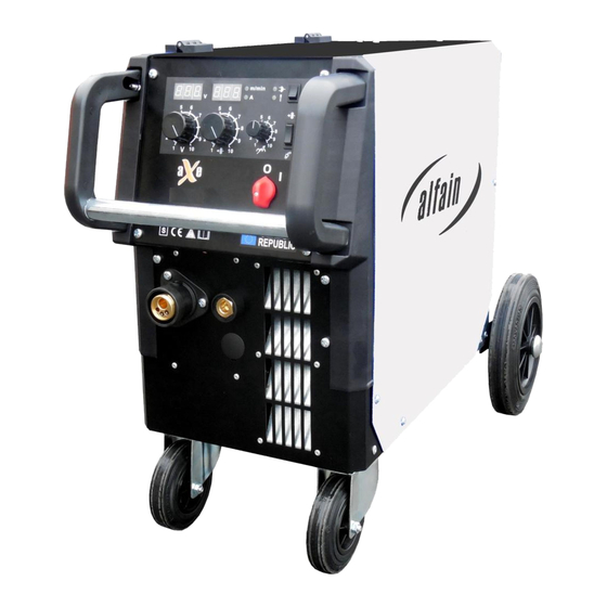
If you decide to use a different torch than the above, it is necessary to choose one, according to your current range and load time of the torch. ALFA IN a.s. is not liable for damage caused by overload welding torches. DESCRIPTION OF THE APPLIANCE MAIN PARTS Picture 1 –... - Page 8 Roll CHOOSING THE FEEDING ROLL In all machines ALFA IN MIG / MAG rolls with two grooves are used. These grooves are intended for two different wire diameters (e.g. 0,8 and 1,0 mm). Rolls for wire feed must comply with the diameter and material of the welding wire.
- Page 9 2320 ADJUSTING THE MACHINE FOR ANOTHER WIRE DIAMETER In all machines ALFA IN MIG / MAG are used rolls with two grooves. These grooves are intended for two different wire diameters (e.g. 0,8 a 1,0 mm). Groove can be replaced by removing the rolls and rotating them, or use a different roll grooves with required dimensions.
- Page 10 D1 so that while stopping the feed, spool will be stopped on time (it will avoid excessive release of wire).However, too tight brake needlessly strains the feeding mechanism and thus slippage may occur in the wire rolls. ALFA IN a.s. © www.alfain.eu...
- Page 11 7. Press button (pic. 8) V3. The welding wire is fed into the torch. After coming off from the torch tube, screw the current nozzle and gas nozzle on. 8. Before welding, spray the area in a gas hose and current nozzle with a separation spray, to prevent damage. ALFA IN a.s. © www.alfain.eu...
- Page 12 F6 shows the required flow, then release the button. The optimum flow is 10-15l/min. 4. After long-term shutdown of the machine or replacement of the torch it is suitable to blow the pipes with protective gas before welding. ALFA IN a.s. © www.alfain.eu...
-
Page 13: Basic Settings
Button Wire Feeding Instant JOB buttons 1-6 Current encoder Control light Material thickness (mm) Control light Wire speed (m/min) Button for selecting the parameters to be displayed Control light Current (A) Left display shows Welding current ALFA IN a.s. © www.alfain.eu... - Page 14 / 4T . The two stroke mode is signalized by LED V17. 1. Tact – press and hold the button the machine will start welding 2. Tact – release the torch button the machine will stop ALFA IN a.s. © www.alfain.eu...
- Page 15 0 - 75 ms (35 ms) (Calibration menu) Calibration menu x.xx (version sw PCB engine) The last menu item is CAL – it is used to enter the calibration menu, which is intended only for authorized service. ALFA IN a.s. © www.alfain.eu...
- Page 16 V13 and V19 at the same time. 2. By means of the button H3 set the function JOB change. 3. By means of buttons H6 (UP) and H7 (DOWN) switch among the saved JOBs. ALFA IN a.s. © www.alfain.eu...
- Page 17 3. Selects synergic curve (program number) using encoder V16 according to the table, which is located inside. To confirm the program number press the encoder V5. Picture 10 – Table of synergic curves ALFA IN a.s. © www.alfain.eu...
- Page 18 Approximate setting for the MIG / MAG welding current and voltage corresponds the empirical relationship U2 = 14 +0.05 I2. According to this relationship, we can determine the required voltage. When setting the voltage, we expect the ALFA IN a.s. © www.alfain.eu...
- Page 19 4 -18 9720 Stainless steel wire 2 - 5 11,5 3 - 6 1440 3 - 12 4320 4 -18 9720 Aluminum wire 2 - 5 3 - 6 3 - 12 1440 4 -18 3240 ALFA IN a.s. © www.alfain.eu...
-
Page 20: Mma Welding (Coated Electrode- Ele)
2. Disconnect the aXe from the mains supply voltage before disassembling. 3. Special maintenance is not necessary for the control unit parts in the Welder. If these parts are damaged for any reason, replacement is recommended. ALFA IN a.s. © www.alfain.eu... - Page 21 The ball is fused to the the nozzle. of the wire at the nozzle. beginning. Adjust the pressure Irregular or no Poor pressure in the according to this wire feed. wire feed rolls instruction manual. ALFA IN a.s. © www.alfain.eu...
- Page 22 / clamps of the machine. The grounding cable is Tighten the earthling poorly attached to the cable in the connector on connector on the the machine. machine. Check and replace if Torch damaged necessary. ALFA IN a.s. © www.alfain.eu...
-
Page 23: Statement Of Warranty
3. ALFA IN will repair or replace, at its discretion, any warranted parts or components that fail due to defects in material or workmanship within the warranty period. -
Page 24: Disposal
As a warranty list serves proof of purchase (invoice) on which is the serial number of the machine, eventually a warranty list below, which is filled in by an authorized dealer. Serial number: Day, month (written in words) and year of sale: Stamp and dealer signature: ALFA IN a.s. © www.alfain.eu...
Need help?
Do you have a question about the AXE 250 IN MIG SYN and is the answer not in the manual?
Questions and answers