GARO GLB Assembly Instructions Manual
Wallbox
Hide thumbs
Also See for GLB:
- Assembly and user instructions manual (27 pages) ,
- Quick start manual (13 pages) ,
- Quick start manual (15 pages)

Related Manuals for GARO GLB


Summary of Contents for GARO GLB
- Page 1 GARO GLB Wallbox Assembly instructions / End User Instruction (EN) GARO AB Box 203, SE–335 25 Gnosjö Phone: +46 (0) 370 33 28 00 info@garo.se garo.se...
-
Page 2: Table Of Contents
Connect GLB Wallbox to local wifi network Ethernet settings RFID (option) Outlet options * G-Cloud Charge current settings / DLM Software Updates / Identification Firmware update for GLB Wallbox not connected to internet via Wifi or LAN Workingflow RFID with multiple wallboxes Care Technical data... - Page 3 However, because continuous for charging. improvement is a goal at GARO, we reserve the right to make Incorrect installation and testing of the GLB Wallbox could product and software modifications at any time.
-
Page 4: Assembly Instructions
• Level • Power drill It is to be fitted to a wall or GARO Wallbox stand, and all • Twisted pair cable (Optional only when DLM is used) Cable: installation must be carried out by an authorized installer and Suitable for Modbus communication. - Page 5 Residual Current protection and must be protected with a max 32A fuse in the supply distribution box. GLB Wallbox without RCCB Type B fitted or DC fault protection in the enclosure must in accordance to IEC 60364-7-722 be protected with a Residual Current GLB Type Device (RCD) Type B.
- Page 6 Assembly instructions Dip Switch Information ON OFF Datalink Endtermination ON, OFF ON = Master Mode, OFF = Slave mode Remote enable input function. ON (default) = Open circuit, OFF = Closed circuit Fuse value in mains cabinet, see below table for settings ON OFF ON OFF ON OFF...
-
Page 7: Step By Step Guide
Assembly instructions Step by step guide Select the appropriate group fuse (1x6A - 3x32A) and cable area for the electrical installation. Some countries require earth fault breakers to be installed. Follow local country regulations and select the appropriate earth fault equipment for the electrical installation. - Page 8 Assembly instructions Option DLM Meter installation (Accessory) Install the DLM meter in the mains cabinet you want to monitor. Use shielded twisted pair cable between the DLM meter and the wallbox. Suitable cables: CAT5 FTP, CAT5e FTP, CAT6 FTP, ELAKY-S, ELAQBY-S or similar.
- Page 9 Assembly instructions Remote enable setting ON (default): Use when not connected to external enable relay. OFF: Use when connected to external enable relay. Master / Slave settings ON (default): Master OFF: Slave Stand allone installation = ON Cluster installation = See Full manual at www.garoemobility.com/support Datalink End termination settings N/A for stand alone installation)
- Page 10 Assembly instructions ON OFF Set SW2 DIP1-3 to Max charge current (A) to vehicle. SWITCH 2 ON OFF Wallbox type ON: Fixed cable OFF: Outlet...
- Page 11 You find SSID and password on the rating label. Serial No / SSID Type in 172.24.1.1 in your web browser and check language label is that the GLB webinterface is visible. This action confirms placed on the side that the GLB Wallbox communication module is working properly.
-
Page 12: Remote Enable Function
Assembly instructions Remote enable function An external relay can be connected to the Remote control terminals to remotely enable the wallbox. • The wallbox can be enabled in two ways: • Enable charging by opening the circuit between the Remote Control connection blocks. -
Page 13: Dynamic Load Management (Dlm) For Stand-Alone Glb Wallbox
The data is transmitted from the • CG EM 112 mains cabinet to the GLB Wallbox, that then is reducing the • CG EM 270 charging current when necessary in order to prevent the mains •... -
Page 14: Setting The Amperage For Main Fuses
(DIP1-3) must be adjusted to correspond with the size and strength must be connected as following: A- (energy meter) to A- of the main fuses. The SW2 (DIP 1-3) which controls the GLB (GLB “E-meter” terminal) and B+ (energy meter) to B+ (GLB Wallbox maximum permitted charging current should be set to “E-meter”... -
Page 15: Dynamic Load Management (Dlm) For Glb Wallboxes In Group
Wallboxes in group Note: Do not change any settings on the internal energymeter. To activate DLM for a group of GLB Wallboxes, a GARO Modbus energy meter must be installed in the supply distribution box. It is also possible to install a 2nd Modbus energy meter when you need to monitor the consumed energy at more than one place. - Page 16 Assembly instructions First and last GLB Wallbox should be end-terminated by SW1 DIP6 (ON), (figure 7) GLB Wallbox with wifi module should be Master, SW1 DIP5 ON. All other boxes are slaves, SW1 DIP5 OFF. SW1 (DIP 5 and 6) settings...
- Page 17 Note: Modbus connection between energy meter and GLB must be connected as following: A- (energy meter) to A- (GLB “E-meter” terminal) and B+ (energy meter) to B+ (GLB “E-meter” terminal) When GLB Wallbox have internal energymeter, connect DLM...
-
Page 18: Installing The Rfid Reader
Assembly instructions Installing the RFID reader Turn off the power to the GLB Wallbox Install the RFID reader as shown in the image above. DIP switches on the RFID card should be set to ON mode. Cable direction to the right... -
Page 19: Dip Switch Settings For Rfid Reader On Individual Glb Wallbox
‘Data Link’. The Data Link cable must be electrically To activate RFID reader on a GLB Wallbox that is stand-alone (not terminated in the first and last wallboxes, via switch SW1 (DIP connected with other GLB Wallboxes), it is important to set the GLB-Wallbox as master (set switch SW1 (DIP 5) to ‘ON). - Page 20 Assembly instructions There must always be one (1pcs) GLB Wallbox as “Master” in the installation and it is set by SW1 DIP5. All other boxes should be slaves and this is set by SW1 DIP6, see (figure 16). SW1 (DIP 5 and 6) settings...
-
Page 21: Lan Connection Via Rj45
Assembly instructions LAN connection via RJ45 LAN connection via RJ45 ethernet-port on the wifi module (only for GLB with installed wifi module) The ethernetport have DHCP as factory default. (figure 19) Mainboard simplified connection diagram Connector for RFID reader FU SE 2A T... -
Page 22: Dimensional Drawing
Dimensional drawing Dimensional drawing (figure 21) -
Page 23: User Instructions
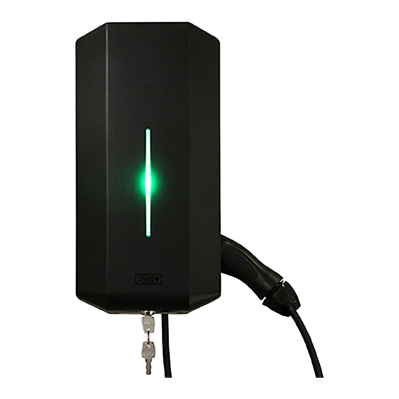
User instructions USER INSTRUCTIONS Congratulations on selecting a GARO GLB Wallbox and The status of the GLB Wallbox can be obtained from the color of contributing to a better environment. The GARO GLB Wallbox is the Indication light (D). an AC charge-station enabling Mode 3 charging which complies Solid green light: charger ready, vehicle not fully with the requirements of IEC 61851-1 and IEC TS 61439-7. -
Page 24: Resetting/Conditioning Of Rccb Or Rcbo
User instructions Resetting/Conditioning of RCCB or RCBO If the GLB Wallbox is equipped with a RCCB or RCBO (H) (figure 24). In the event of overload/earth fault, these can be tripped. These components must also be conditioned every 6 months. -
Page 25: Web Interface
• Activate/deactivate GLB Wallbox Reset of wifi settings If problem to connect to GLB accesspoint or other similar problem, press SW3 on main board “(figure 20)” on page 21 for 3sek to reset all wifi settings to factory default (performed by a person with necessary knowledge). -
Page 26: Home Meny
Web interface Home meny Click to set time Double click GARO logo for extended information. Wallbox status Dropdown list *: Available for charging Not available for charging Schedule An installed DLM meter is visible here. Note, it can take up to 5min before the DLM meter is visible after power * N/A for older wallboxes Car and text shows present status. - Page 27 Web interface Home meny List of all different statues...
- Page 28 Not available for chargning mean that the GLB Wallbox is deactivated. * Schedule means that you can set periods when the GLB Wallboxes should be activated. Choose wanted period and press Book. *, ** Click on a period to delete it*...
- Page 29 Web interface Click the + to show extended information. The information is updated every minute (only displayed with installed DLM meter) Click Refresh to search for connected wallboxes Multiple connected wallboxes are shown in a list Click Identify to start white blink and ticking sound from chosen wallbox.
-
Page 30: Energy Meny
Web interface Energy meny In wallboxes without internal energymeter, Energy meter not installed is shown. Choose energy meter GLB Wallbox with internal energymeter show energy consumption here. Choose consumption period Settings Click + to see extended information. -
Page 31: Wifi Settings
Field for own password. Enable internet hotspot (only visible for LAN connected wallbox). Click Save after changed settings. Connect GLB Wallbox to local wifi network General information Only 2,4GHz wifi network are supported. 5GHz wifi network is not supported. Firewall/router must handle outgoing request to: * 8.8.8.8 via ICMP(ping) -
Page 32: Ethernet Settings
Web interface Ethernet settings You can connect the wallbox to a LAN via wifi modules ethernet port. Ethernet-settings – More information shows the Ethernetports MAC adress. Dropdown list • Obtain IP automatically • Static IP Current IP adress. Click Save after changed settings. Static IP require manual type in IP adress, Netmask and Gateway. -
Page 33: Rfid (Option)
Web interface RFID (option) Note, require installed RFID reader. Tick Activate RFID Check box to activate the RFID authentification function. Click Add new tag. Type in or read the RFID tag number from the wallbox. By click Read tag from wallbox, the RFID reader can read the tag number you hold in front of the reader. -
Page 34: Outlet Options
Web interface Outlet options * Note, only for standalone Master wallbox with outlet. Tick Lock cable to outlet in cases when you want to cable to be locket to the outlet. The wallbox will lock the cable at next charging session. Untick Unlock cable in case of power outage if you want the outlet to lock the cable in case of power outage. -
Page 35: Charge Current Settings / Dlm
Web interface Charge current settings / DLM Minimum charging current* Note, only for standalone Master wallbox Minimum charging current – more information show information window: This setting allows you to set the minimum starting current (in amperes) for the wallbox, some car models require a higher starting current to properly charge. - Page 36 Web interface LB Meter settings are shown in cases with DLM meter adress 100 or 101 installations Currentlimited (A): Set Distribution board fuse size. In systems where Power-limit is neccessary, tick the box and set the Powerlimit value wanted in the distribution board.
- Page 37 Web interface Set wanted value for each wallbox in the system. Click Save after changed settings. Note, in systems with multiple connected wallboxes, make the setting for each box in the system. All wallboxes are shown in a list.
-
Page 38: Software Updates / Identification
Click to update list of connected boxes. Update all connected wallboxes* Click to update connected wallboxes. Note, a GLB update will take up to 5 min. Firmware update for GLB Wallbox not connect- ed to internet via Wifi or LAN By Computer / Android mobile or tablet: 1. -
Page 39: Workingflow Rfid With Multiple Wallboxes
• Click Save. • Repeat step 4 until all tags are registred. Care We recommend that you clean the GLB Wallbox with a soft, dry cloth. Never use detergent. - Page 40 Indication Error type Action Solid red light RCCB has tripped or EV earth Reset. Refer to section on resetting check error is detected. the residual-current or personal protective current breaker. Solid red light for 3 sec RFID tag not accepted. Red fast flash DC current >6mA - charging has stopped.
-
Page 41: Technical Data
Technical data Product type All GLB models Standards / Directives IEC 61851-1 and IEC 61439-7 EMC Classification: 2014/30/EU Installation method: Wall Installation environment: Indoor / Outdoor Location type: Non-restricted Access Rated Voltage: 230V / 400V 50Hz Installation systems: TT, TN and IT systems...
Need help?
Do you have a question about the GLB and is the answer not in the manual?
Questions and answers