Table of Contents
Advertisement
Quick Links
Advertisement
Table of Contents
Troubleshooting

Related Manuals for EP Equipment EPT20-15ET


Summary of Contents for EP Equipment EPT20-15ET
- Page 3 This manual applies to: Model Specifi cations EPT20-15ET 1,500 kg Capacity EPT20-15ETL 1,500 kg Capacity, Ultra-low Placement Some sections of the manual only involve certain model, please refer to the manual according to the actual confi guration of the vehicle.
- Page 4 Please strictly adhere to these safety instructions to avoid personal injury. Please pay attention to the important safety instructions. Instructions. Copyright Copyright of Service Manual belongs to EP Equipment Co., Ltd. EP Equipment Co., Ltd. EP Industrial Park, Xiaquan Village, Dipu Town, Anji County, Zhejiang Province www.ep-zl.com...
-
Page 5: Table Of Contents
TABLE OF CONTENTS TABLE OF CONTENTS SECTION PAGE 1. INFORMATION & SPECIFICATIONS ......1.1 After-sales Service Platform ......... 1.2 Introduction ..............1.3 Common Tools .............. 1.4 General Tightening Torques ......... 2. MAINTENANCE ............... 2.1 Overview..............2.2 Maintenance ............... 2.2.1 Cleaning ................12 2.2.2 Inspection ..............12 2.2.3 Lubrication ..............16 3. - Page 6 TABLE OF CONTENTS TABLE OF CONTENTS SECTION PAGE 4.3 Lifting Mechanism............4.3.1 Fork Inspection ..............31 4.3.2 Connecting Rod Adjustment ..........31 4.3.3 Removal and Installation ..........32 5. DRIVE SYSTEM ............. 5.1 Drive Assembly ............5.1.1 Removal and Installation ..........36 5.2 Electromagnetic Brakes..........5.2.1 Removal and Installation ..........37 5.2.2 Faults and Causes............37 5.2.3 Checking and Testing ............38...
- Page 7 TABLE OF CONTENTS TABLE OF CONTENTS SECTION PAGE 7.2 Pump and Motor Assembly......... 7.2.1 Removal and Installation ..........57 7.2.2 Component ..............58 7.3 Pump Motor ..............7.3.1 Removal and Installation ..........58 7.3.2 Faults and Causes............59 7.3.3 Checking and Testing ............59 7.4 Pump Contactor............7.4.1 Faults and Causes............60 7.4.2 Checking and Testing ............61 7.4.3 Control Circuit Troubleshooting ........61...
- Page 8 TABLE OF CONTENTS TABLE OF CONTENTS SECTION PAGE 8.5.2 Faults and Causes............79 8.5.3 Checking and Testing ............79 8.5.4 Control Circuit Troubleshooting ........79 8.6 Lifting Limit Switch ............8.6.1 Removal and Installation ..........80 8.6.2 Faults and Causes............80 8.6.3 Checking and Testing ............80 8.6.4 Control Circuit Troubleshooting ........80 8.7 Interlock Switch ............
- Page 9 TABLE OF CONTENTS TABLE OF CONTENTS SECTION PAGE B1-2 Use of Battery ............B1-2.1 Pre-use Checks ............107 B1-2.2 Discharging ...............107 B1-2.3 Charging ..............108 B1-2.4 Temperature ..............108 B1-3 Maintenance & Care ..........B1-3.1 Daily Maintenance ............108 B1-3.2 Weekly Maintenance ..........108 B1-3.3 Monthly Maintenance ..........109 B1-3.4 Care ................109 B1-4 Storage ..............
- Page 10 TABLE OF CONTENTS REV. 09/2016...
- Page 11 SAFETY WARNING For your own safety and that of others, please observe the following safety instructions: Thorough and normative maintenance is one of the most important prerequisites to ensure stable and reliable operation of truck. Neglecting regular maintenance could easily lead to the truck malfunction and failure, and potential threats to staff and operational safety.
-
Page 12: Information & Specifications
1. INFORMATION & SPECIFICATIONS... - Page 13 NOTE:...
-
Page 14: After-Sales Service Platform
INFORMATION & SPECIFICATIONS 1.1 After-sales Service Platform Claims/Replacement Parts Service Platform: After-sales Maintenance Service Platform: Customer Customer Claim Form Claim Form nxsp@ep-zl.com nxsp@ep-zl.com Customer service to input Customer service to input into After-sales System. into After-sales System. A f t e r - s a l e E n g i n e e r t o After-sale Engineer to call call back to confirm the back to confirm about the... -
Page 15: Introduction
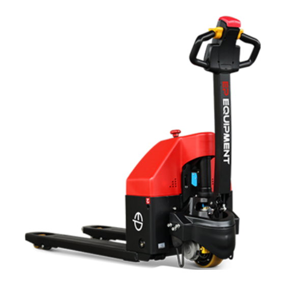
INFORMATION & SPECIFICATIONS 1.2 Introduction Name Name Control Lever Battery Emergency Stop Switch Chassis Charge Gauge Balance Stand / Caster Wheel LED Charging Indicator Drive Wheel Key Switch Lower Cover Upper Cover Lift Cylinder Charging Plug REV. 09/2016... -
Page 16: Common Tools
INFORMATION & SPECIFICATIONS This series are electric pallet trucks. Its import- ant structure is as shown in Figure 10001. WARNING - Please refer to the nameplate for rated load capacity of the vehicle. - The vehicle can only be used on the level gro- und indoors, never use it on mezzanine or balcony area. -
Page 17: General Tightening Torques
INFORMATION & SPECIFICATIONS 1.4 General Tightening Torques Screws or bolts used on the truck are of 8.8 grade or higher performance level. When you are conducting truck maintenance, you can refer to Table 1.4.1 and Table 1.4.2 to select the suitable screws or bolts for replace- ment. - Page 18 INFORMATION & SPECIFICATIONS Table 1.4.2 Metric Screws/Bolts Tightening Torque Table (n•m) Performance Level 10.9 12.9 Nominal Diameter (mm) Proof Stress (MPa) 10~12 14~17 17~20 16~18 25~30 34~41 41~48 M8×1 17~20 27~32 37~43 43~52 31~36 49~59 68~81 81~96 M10×1 35~41 55~66 76~90 90~106 55~64...
- Page 19 INFORMATION & SPECIFICATIONS REV. 09/2016...
-
Page 20: Maintenance
2. MAINTENANCE... - Page 21 NOTE:...
-
Page 22: Overview
MAINTENANCE 2.1 Overview NOTE Only by performing regular vehicle maintenance Under harsh working conditions: such as, the and repair, can ensure the continuous and external temperature is too high or too low, reliable use of the truck. dusty, or implementing multiple shifts per day, Only specially trained and qualified personnel the maintenance and care interval should be a r e c a p a b l e o f m a i n t e n a n c e a n d r e p a i r... -
Page 23: Maintenance
MAINTENANCE Regular inspection and maintenance under 2.2 Maintenance harsh conditions of use: 2.2.1 Cleaning Under harsh working conditions, especially: - Dusty environment Do not use flammable liquids to clean the - Corrosive environment truck. - Cold storage environment Before starting to clean, all necessary The maintenance intervals should be shortened security measures must be taken to prevent by half. - Page 24 MAINTENANCE Table 2.1 Inspection & Maintenance List Interval in days/months/years 60 d 90 d Interval in hours 1000 2000 Functions and Control Check the functions of the operation switches and display Check alarm system functions Check interlock switch functions Check the emergency switch functions Check the cables for damage and if the terminals are secure Check the lifting limit switch functions...
- Page 25 MAINTENANCE Table 2.1 Inspection & Maintenance List (Continued) Interval in days/months/years 60 d 90 d Interval in hours 1000 2000 Power Supply & Drive System Check the bearing bridge for damage or crack Check the travel speed Hydraulic System Check the functions of hydraulic system Check if the hoses, pipes and interfaces are fastened or sealed securely, and check if there is damage Check the cylinders for leaks...
- Page 26 MAINTENANCE Table 2.1 Inspection & Maintenance List (Continued) Interval in days/months/years 60 d 90 d Interval in hours 1000 2000 Lifting Mechanism Check the connecting rod mechanism for wear or damage Check whether the pin shaft is fi xed securely Check and lubricate the moving parts of connecting A / L rod mechanism...
-
Page 27: Lubrication
MAINTENANCE Please see Table 2.2 for the lubricants used in 2.2.3 Lubrication this truck. Lubricant CAUTION Improper operations may constitute hazards to the operator's health and life, as well as to The use and disposal of lubricants must be the surrounding environment. carried out in strict accordance with the manufa- cturer's regulations. - Page 28 MAINTENANCE Table 2.2 Lubricants Code Type Specifi cation Amount Position Anti-wear hydraulic oil L-HM46 Hydraulic 0.65 L Low temperature anti-wear System L-HV32 hydraulic oil (cold storage) Sliding surface Multi-purpose grease Polylub GA352P Appropriate amount (See Table 2.3) Grease (MoS 100 grams Gearbox Table 2.3 Sliding Surface Lubrication Table...
- Page 29 MAINTENANCE REV. 09/2016...
-
Page 30: Structure & Functions
3. STRUCTURE & FUNCTIONS... - Page 31 NOTE:...
-
Page 32: Structure & Functions
STRUCTURE & FUNCTIONS 3.1 Structure & Functions 3.1.1 Travel Switch Location: control lever; Function: to output travel speed signal to the drive controller; Description: when the vehicle is powered on, the travel switch is at Middle position; Note: Unserviceable. Travel Switch 3.1.2 Lifting/Lowering Switch Location: control lever;... -
Page 33: Emergency Stop Switch
STRUCTURE & FUNCTIONS 3.1.5 Emergency Stop Switch Emergency Stop Switch Location: electrical mounting plate; Function: to disconnect the circuit and switch off all electrical functions, achieving emergency braking; Description: under normal circumstances, switch cover is at high position, and the circuit is connected, when pressing this switch, the circuit is disconnected;... -
Page 34: Buzzer
STRUCTURE & FUNCTIONS 3.1.9 Buzzer Location: electrical mounting plate; Function: can provide sound alarm through the operation to horn switch operation; Description: 24V operating voltage; Note: Unserviceable. Buzzer 3.1.10 Fuse Location: electrical mounting plate; Function: overcurrent protection; Description: fusing current is 100A; Note: Unserviceable. -
Page 35: Lifting Limit Switch
STRUCTURE & FUNCTIONS 3.1.13 Lifting Limit Switch Location: bracket; Function: limit the lifting height of the fork; Description: lifting limit switch is normally closed. When the fork is lifted in higher position (that is to trigger the limit switch to disconnect), lifting will be limited;... -
Page 36: Pump Contactor
STRUCTURE & FUNCTIONS 3.1.17 Pump Contactor Location: outside of the pump motor; Function: to connect and disconnect circuit of pump motor, and to control the power trans- mission of pump motor; Description: the signal obtained by drive controller from lifting switch controls the ON/ OFF of pump contactor;... - Page 37 STRUCTURE & FUNCTIONS REV. 09/2016...
-
Page 38: Chassis System
4. CHASSIS SYSTEM... - Page 39 NOTE:...
-
Page 40: Load Wheel
CHASSIS SYSTEM 4.1 Load Wheel 4.1.1 Removal and Installation Removal Lift the vehicle carefully with lifting equipment through the lifting holes at back; WARNING Make sure the lifting equipment is solid and secure, and the load capacity should be greater than the total weight of the vehicle. -
Page 41: Faults And Causes
CHASSIS SYSTEM 4.2 Cover CAUTION 4.2.1 Removal and Installation When installing, please apply appropriate amount of grease on the axle fi rst. Removal (See Section 2.2.3 for specifi cations) Unscrew the two large flat-head screws (1), Quality of tyres directly affects the stability and and pull out the upper cover (2);... -
Page 42: Lifting Mechanism
CHASSIS SYSTEM 4.3 Lifting Mechanism 4.3.1 Fork Inspection Lower the forks completely down: Lift the forks completely: The truck is equipped with batteries, the height The truck is equipped with batteries, the height from fork surface at center of load wheel to the from fork surface at center of load wheel to the ground (h1): ground (h2):... -
Page 43: Removal And Installation
CHASSIS SYSTEM Tap the coiled elastic cylinder (11) into the 4.2.3 Removal and Installation short axis (12), and tap the short axis (12) Removal out from the side to separate the lower connecting rod with the bearing bridge; - Lift the vehicle carefully with lifting equipment Remove the circlip (8) from the holes at both through the lifting holes at at front and back;... -
Page 44: Drive System
5. DRIVE SYSTEM... - Page 45 NOTE:...
- Page 46 DRIVE SYSTEM Drive System Name Drive Assembly Electromagnetic Brakes Gear Cover Gear Case Drive Wheel Drive Motor REV. 09/2016...
-
Page 47: Drive Assembly
DRIVE SYSTEM 5.1 Drive Assembly 5.2 Electromagnetic Brakes 5.1.1 Removal and Installation The truck is braked through electromagnetic brake. When the truck is powered off, the Removal electromagnetic coil (6) doesn't absorb the pressure plate (8), the friction force generated Remove the drive cover (see Section 4.2);... -
Page 48: Removal And Installation
DRIVE SYSTEM 5.2.1 Removal and Installation CAUTION Removal When installing the brake gear (7), make sure The brake is installed on the drive motor. See the flat key is installed on the shaft of drive Figure 30204 motor (8). Adjustment The electromagnetic brake used in this series of truck is an air gap adjustment-free brake. -
Page 49: Checking And Testing
DRIVE SYSTEM Air Gap Checks After the coil is powered off, the Fault pressure plate won't release Switch off the truck power connections and Cause Foreign body blocking pull out the brake connectors; Check the air gap between electromagnetic Fault Abnormal noise after absorption coil and pressure plate with feeler gauge: a. -
Page 50: Control Circuit Troubleshooting
DRIVE SYSTEM 5.2.4 Control Circuit Troubleshooting Brake Control Circuit (Figure 30207) Check if the circuit is broken by using a multi- meter: Set the multimeter to ON-OFF; Check if #6 circuit (circuit between brake and controller) is conducted; Check if #7 circuit (circuit between brake and controller) is conducted;... -
Page 51: Drive Wheel
DRIVE SYSTEM - Loosen the six screws (9) with a wrench, and 5.3 Drive Wheel dismantle the large ring gear (10), bearing (11) and drive wheel (12) by order. 5.3.1 Removal and Installation Removal Installation Remove the brake (see Section 5.2.1); - Install according to the reverse order of rem- (See Figure30208) oval. -
Page 52: Drive Motor
DRIVE SYSTEM - After replacing carbon brush, running opera- 5.4 Drive Motor tion must be carried out to the carbon brush: This truck obtains drive force through DC motor. By running the motor with repeated lifting, letting the carbon brush to be fully running, making its surface smooth to fi... -
Page 53: Checking And Testing
DRIVE SYSTEM Circuit of drive motor Fault Motor smoking or burning smell Stator winding short circuit, motor Cause burnt Fault Excessive temperature rise a. Stator winding short circuit; b. Motor positive and negative electrodes with surface Cause oxidation, resistance increases and results in heating;... -
Page 54: Gearbox
DRIVE SYSTEM 5.5 Gearbox 5.5.1 Removal and Installation See Section 5.3.1 . CAUTION Please add gear oil to the grease nipple on the gearbox cover (see Section 2.2.3 for specifi ca- tion and fi lling amount) 5.5.2 Faults and Causes Fault Gearbox Abnormal Noise a. - Page 55 DRIVE SYSTEM REV. 09/2016...
-
Page 56: Operating System
6. OPERATING SYSTEM... - Page 57 NOTE:...
-
Page 58: Control Lever
OPERATING SYSTEM 6.1 Control Lever 6.2 Button Switch Control lever is used to control the travel, lifting, Push button switch is the switch that makes lowering, horn and emergency reverse of the the dynamic and static contacts ON or OFF to vehicle. -
Page 59: Faults And Causes
OPERATING SYSTEM Lifting/Lowering Button 6.2.2 Faults and Causes (See Figure 30302) Operate the push button switch, Remove switch assembly (5 or 9) form cap Fault but the vehicle responds with no (1); action Remove pin (6) securing buttons and remove a. -
Page 60: Control Circuit Troubleshooting
OPERATING SYSTEM Lifting Switch (See Figure 30304) - Carry out ON/OFF test to the circuit between #1 and #2 with a multimeter: push button switch at original position, broken circuit; press the button , the circuit is conducted. Lowering Switch (See Figure 30304) - Carry out ON/OFF test to the circuit between #1 and #3 with a multimeter:... - Page 61 OPERATING SYSTEM Lowering Switch Control Circuit Emergency Reverse Switch Control (Figure 30306) Circuit (Figure 30311) Check if the circuit is broken by using a multi- See Section 6.3.4 . meter: Set the multimeter to ON-OFF; Check if #1 circuit (circuit between lowering switch and key switch) is conducted;...
-
Page 62: Travel Switch
OPERATING SYSTEM 6.3 Travel Switch 6.3.2 Faults and Causes Travel switch provides forward or backward in- Operate travel switch, the vehicle Fault put signals for the vehicle. cannot go forward or backward a. Travel switch failure; Cause b. Travel switch circuit not 6.3.1 Removal and Installation conducted. -
Page 63: Control Circuit Troubleshooting
OPERATING SYSTEM Place the travel switch at Middle position. Respectively, measure the voltage of pin (11), pin (12) and pin (22) of the travel switch: if the voltage is not 0, it indicates the travel switch failure, needs to be replaced; if the voltage is 0, indicating the switch is normal, move to the next step. -
Page 64: Hydraulic System
7. HYDRAULIC SYSTEM... - Page 65 NOTE:...
-
Page 66: Overview
HYDRAULIC SYSTEM The system pressure of the entire hydraulic Hydraulic Oil system pressure is provided by hydraulic power Hydraulic oil for truck: unit system, which is used for lifting. While the Specifi cations: Anti-wear Hydraulic Oil L-HM46. hydraulic power unit is equipped with a relief valve to ensure that the entire system pressure * For cold storage: Low Temperature Anti-wear is always within the safety limits that can lift the... -
Page 67: Hydraulic Schematic Diagram
HYDRAULIC SYSTEM 7.1.1 Hydraulic Schematic Diagram REV. 09/2016... -
Page 68: Pump And Motor Assembly
HYDRAULIC SYSTEM - Unscrew the two screws (3) with a wrench 7.2 Pump and Motor Assembly and remove the hydraulic station from the 7.2.1 Removal and Installation electrical mounting plate. Installation - Install according to the reverse order of rem- oval. -
Page 69: Component
HYDRAULIC SYSTEM 7.2.2 Component 7.3 Pump Motor 7.3.1 Removal and Installation Removal Remove the pump and motor assembly; Remove the 2 long screws (1) on the motor end cover, and remove the pump motor (2) from the valve block (3); If you need to replace carbon brush (4). -
Page 70: Faults And Causes
HYDRAULIC SYSTEM Adjustment Motor with abnormal noise or Fault vibration After replacing the steering motor or carbon brush, conduction test must be carried out to a. Uneven clearance between the motor (see Section 7.3.3). stator and rotor; After replacing carbon brush, running opera- Cause b. -
Page 71: Pump Contactor
HYDRAULIC SYSTEM Circuit between pump motor and pump 7.4 Pump Contactor contactor This truck is using DC contactor with normally- o p e n c o n t a c t s . A n d t h e O N / O F F o f t h e Negative contactors is controlled through controller, thus to achieve the control of ON/OFF of the vehicle. -
Page 72: Checking And Testing
HYDRAULIC SYSTEM 7.4.2 Checking and Testing Resistance Judgment Measurement Checking Approx. 22 Ω Normal - Check if the pump contactor and appearance Coil shorting of cables are in good condition, and if the 0 Ω (replace the contactor) plug connection is secure; Coil breaking ∞... -
Page 73: Solenoid Valve
HYDRAULIC SYSTEM 7.5 Solenoid Valve Fault Internal leakage When solenoid valve coil is energized (there Damaged seals or spring Cause is voltage between coil end A and B), the deformations electromagnetic coil generates electromagnetic Fault External leakage force, and the spool will move, the valve will open, and the vehicle will be lowered. -
Page 74: Control Circuit Troubleshooting
HYDRAULIC SYSTEM - Remove the solenoid valve, take out the spool and spool sleeve, clean with CCI4 to enhance the fl exibility of the moving of spool within the spool sleeve. During disassembly, pay attention to the sequence of assembly and position of external wiring for correct re- assembly and wiring, also check the oil mist spray orifi... -
Page 75: Reach Cylinder
HYDRAULIC SYSTEM Upon removal, the damage to cylinder 7.6 Reach Cylinder threads, oil port threads, cylinder cap threads, 7.6.1 Cylinder Removal Precautions piston rod surface and inner cylinder wall should be prevented. Before removing the cylinder, be sure to reli- In order to prevent piston rod from bending or eve the hydraulic circuit fi... -
Page 76: Cylinder Installation Precautions
HYDRAULIC SYSTEM CAUTION Cylinder Cap O-ring is quite flexible and easy to install, but it must not be pulled up to the extent of permanent deformation, nor scroll it while installing; Y-ring or X-ring needs to be identifi ed if it is Cylinder Wrenches for shaft or hole to avoid misplacement;... -
Page 77: Removal And Installation
HYDRAULIC SYSTEM Install the cylinder according to the reverse 7.6.3 Removal and Installation order of removal ; Add hydraulic oil of the same specifications into the tank, see Section 2.2.3; Pull out emergency stop switch and turn on the key switch; Repeat Lift - Lower cylinder to discharge the air within the tubings and cylinder;... - Page 78 HYDRAULIC SYSTEM CAUTION Use suitable hose clamps to avoid cylinder deformation caused by severely tight hose clamp. Carry out the maintenance work in a clean environment to prevent impurities from entering into cylinder, causing cylinder damage. During the installation, hydraulic oil of the same specifications must be used for cleaning or lubrication.
-
Page 79: Hydraulic Troubleshooting
HYDRAULIC SYSTEM 7.7 Hydraulic Troubleshooting Fault Symptom Failure Causes Troubleshooting Measures a. Insuffi cient oil; 1. Check the hydraulic oil level. b. High viscosity of oil; 2. Replace the hydraulic oil. c. Oil suction pipe air leak; 3. Check the oil suction pipe. Noisy pump d. -
Page 80: Hydraulic Symbol
HYDRAULIC SYSTEM 7.8 Hydraulic Symbol Symbol Description Symbol Description Tank Pipe end below liquid Explosion-proof valve level Tank Pipe end above liquid Check valve level Cylinder Filter Single-acting direction Service line (Supply line or return Relief valve line) Control line Throttle valve (Drain line) With pressure... - Page 81 HYDRAULIC SYSTEM REV. 09/2016...
-
Page 82: Electrical System
8. ELECTRICAL SYSTEM... - Page 83 NOTE:...
-
Page 84: Controller
ELECTRICAL SYSYTEM 8.1 Controller 8.1.2 Controller Interface Function Traction Controller (1212) 8.1.1 Removal and Installation Removal J1 Interface Remove the upper cover; (See Section 4.2.1) Remove the wiring harness and cables on the controller; Unscrew the two screws (1) with a wrench and remove the controller (2) and cooling fi... - Page 85 ELECTRICAL SYSYTEM J3 Interface J1 Interface - Continued Pin No. Description J1#11 J1#12 Reverse switch J1#13 J1#14 J2 Interface (Handheld unit communication interface) J3 Interface Pin No. Description Positive of electromechanical brake J3#1 coil. Negative of electromechanical brake J3#2 coil. Terminal stud J2 Interface Pin No.
-
Page 86: Fuse
ELECTRICAL SYSYTEM 8.2 Fuse The entire vehicle is installed with two fuses altogether. When there is fuse failure, the truck may not be able to run properly due to that. Status Function Fuse 1 Fuse 2 Ο Fuse 1 150A ×... -
Page 87: Checking And Testing
ELECTRICAL SYSYTEM 8.2.2 Checking and Testing Checking - Check the fuses for damage, check the connectors at terminal lugs for loosening or poor connection of leads. Testing Turn the key switch to "OFF", remove key; pull out the battery plug and disconnect the power supply. -
Page 88: Key Switch
ELECTRICAL SYSYTEM 8.3 Key Switch 8.3.2 Faults and Causes Key switch is used to START / STOP the truck. Turn the key switch to “ON”, the Fault vehicle won’t start a. Key switch failure; 8.3.1 Removal and Installation Cause b. Key switch circuit not conducted. Removal Turn the key switch to “OFF”, the Fault... -
Page 89: Charge Gauge
ELECTRICAL SYSYTEM 8.4 Charge Gauge 8.4.3 Checking and Testing Charge gauge is used to display remaining Checking battery power of forklift, working hours (this - Check if the appearance of charge gauge its function is available on the component with wiring harness are in good condition, and if timer function). -
Page 90: Led Charging Indicator
ELECTRICAL SYSYTEM 8.5 LED Charging Indicator 8.5.2 Faults and Causes LED charging indicator is used to display Fault No display from indicator charge status, which can display in three colors: a. Indicator failure; red, yellow and green. Cause b. Indicator circuit not connected; c. -
Page 91: Lifting Limit Switch
ELECTRICAL SYSYTEM 8.6 Lifting Limit Switch Lifting limit switch pressed, lifting Fault mechanism does not stop 8.6.1 Removal and Installation a. Lifting limit switch failure; Removal Cause b. Lifting limit switch shorted (short circuit). 8.6.3 Checking and Testing Checking Check if the appearance of limit switch and its wiring harness are in good condition, and if the connectors are connected securely;... -
Page 92: Interlock Switch
ELECTRICAL SYSYTEM 8.7 Interlock Switch Interlock switch pressed, the Fault vehicle cannot travel 8.7.1 Removal and Installation a. Interlock switch failure; Removal Cause b. Interlock switch with broken circuit. 8.7.3 Checking and Testing Checking Check if the appearance of interlock switch and its wiring harness are in good condition, and if the connectors are connected securely;... -
Page 93: Speed Mode Switch (Optional)
ELECTRICAL SYSYTEM Normally-opened (NO): 8.8 Speed Mode Switch (Optional) Terminal (2) and Terminal (3) for connection of 8.8.1 Removal and Installation wiring harness connector to switch base Removal 8.8.3 Faults and Causes When left or right steering angle ≥ Fault 45°, but travel speed of forklift is not reduced a. -
Page 94: Control Circuit Troubleshooting
ELECTRICAL SYSYTEM Testing - Enter Monitor Menu to check the status of the switch: "Mode Input", press the switch, if the display does not change, then it indicates the switch or its circuit failure; Turn the key switch to "OFF", remove key; pull out the battery plug and switch off the power supply. -
Page 95: Handheld Unit (Optional)
ELECTRICAL SYSYTEM - Turn on the key switch, pull out emergency 8.9 Handheld Unit (Optional) stop switch, the display of handheld unit will Handheld unit must be used together with con- be fl ashing: troller, if necessary, it can be purchased from if the connection is successful: The program- our company or dealer. -
Page 96: Parameter Settings
ELECTRICAL SYSYTEM 8.9.3 Parameter Settings THROTTLE MENU CAUTION Paramete Setting Without the written permission of equipment Type manufacturer or its agent, it is strictly prohibit- ed to change any of the parameters in "PARA- Neutral Input METERS". PotHigh Traction Controller Parameter Settings PotLow Neutral Deadband DRIVE MENU... - Page 97 ELECTRICAL SYSYTEM HORN MENU COMPENSATION MENU Paramete Setting Paramete Setting Reverse Beep IR Comp Beep Constant Anti-Rollback Comp MOTOR MENU EMERGENCY REVERSE MENU Paramete Setting Paramete Setting System Resistance Speed Resistance Auto Comp Time Limit Auto Comp Current Limit Decel Rate Speed Scaler Accel Rate Current Rating...
-
Page 98: Tester Menu
ELECTRICAL SYSYTEM 8.9.4 TESTER Menu The parameters in Monitor Menu are real- time presentation of the running status of the equipment. Traction Controller (1212) Parameters Description Remark Display the current temperature ( ℃ ) Temp Check the temperature of controller Battery Voltage Check the voltage of storage battery Display the current voltage ( V ) -
Page 99: Controller Error Message
ELECTRICAL SYSYTEM to the vehicle, LED will twinkle and indicate the 8.10 Controller Error Message fault code; LED won’t restore to the extinguish- The error message can be obtained in two ways: ing state until the fault is eliminated. 1) By reading the appropriate display on the LED indicates two digit codes: for example, digit handheld unit ;... - Page 100 ELECTRICAL SYSYTEM Error Message BLINKS BLINKS EXPLANATION Possible cause digit 1 digit 2 Error text 1. Battery voltage >31 volts. 2. Vehicle operating with OVERVOLTAGE battery voltage too high charger attached. FAULT 3 . I n t e r m i t t e n t b a t t e r y connection.
- Page 101 ELECTRICAL SYSYTEM Error Message BLINKS BLINKS EXPLANATION Possible cause digit 1 digit 2 Error text 1.Motor voltage does not correspond to throttle request. HARDWARE motor voltage out of 2.Short in motor or in motor FAILSAFE range wiring. 3. Controller failure. ★ EE CHECKSUM EEPROM fault 1.
-
Page 102: Electrical Schematic Diagrams
ELECTRICAL SYSYTEM 8.11 Electrical Schematic Diagrams Charge Gauge with Timer + Emergency Reverse External Control PUMP Lifting SW. CONTACTOR Lifting Limit SW. Lifting SW. Lowering SW. E-VALVE Lowering SW. HORN Horn SW. BELLY POTLOW ACCEL REV. E-BRAKE Speed Mode SW. CHARGER Interlock SW. - Page 103 ELECTRICAL SYSYTEM Charge Gauge without Timer + Emergency Reverse External Control PUMP Lifting SW. CONTACTOR Lifting Limit SW. Lifting SW. Lowering SW. E-VALVE Lowering SW. HORN Horn SW. BELLY POTLOW ACCEL REV. E-BRAKE Speed Mode SW. CHARGER Interlock SW. Pump Motor Pump Contactor Emergency SW.
- Page 104 ELECTRICAL SYSYTEM Charge Gauge with Timer + Emergency Reverse Internal Control PUMP Lifting SW. CONTACTOR Lifting Limit SW. Lifting SW. Lowering SW. E-VALVE Lowering SW. HORN Horn SW. POTLOW E-BRAKE BELLY SW. Speed Mode SW. CHARGER Interlock SW. Pump Motor Pump Contactor Emergency SW.
-
Page 105: Cable Wiring Diagrams
ELECTRICAL SYSYTEM 8.12 Cable Wiring Diagrams Name Name Cable C2 Cable B- Power Cable BATT+ Pump Motor Cable PA- Cable M2 Pump Motor Cable PA+ Cable M1 Cable C3 Cable B+ REV. 09/2016... -
Page 106: Wiring Harness And Connectors
ELECTRICAL SYSYTEM 8.13 Wiring Harness and Connectors REV. 09/2016... - Page 107 ELECTRICAL SYSYTEM REV. 09/2016...
-
Page 108: Troubleshooting
9. TROUBLESHOOTING... - Page 109 NOTE:...
-
Page 110: Preparation Before Troubleshooting
TROUBLESHOOTING 9.1 Preparation Before Troubleshooting CAUTION Park the truck on level ground and block the If the battery voltage is still abnormal after being wheels with wooden wedges; charged: open the battery compartment, check Fully lower the fork and press the emergency the voltage of each battery and its connection stop switch. -
Page 111: Troubleshooting Solutions Of Common Faults
TROUBLESHOOTING 9.2 Troubleshooting Solutions of Common Faults Table 9.1 lists the common faults that may occur and handling methods. Mainly consists of the following items: Table 9.1 Troubleshooting of Common Faults Fault Fault Symptom Troubleshooting Order * Troubleshooting Measures Power supply 1. - Page 112 TROUBLESHOOTING Table 9.1 Troubleshooting of Common Faults (continued) Fault Fault Symptom Troubleshooting Order * Troubleshooting Measures Hydraulic 1. The vehicle cannot 1. Pump motor does not work: 1. Pump motor does not work: Failure lift a. Pump motor or its circuit 1) Check the pump motor and its connection failure connection circuit;...
- Page 113 TROUBLESHOOTING Table 9.1 Troubleshooting of Common Faults (continued) Fault Fault Symptom Troubleshooting Order * Troubleshooting Measures Lift Failure 3. Slow Lifting of a. Overload 1) Refer to the rated capacity Vehicle marked on the nameplate; b. Hydraulic pipeline leakage 2) Check the pipe and hydraulic c.
-
Page 114: Appendix
APPENDIX... - Page 115 NOTE:...
-
Page 116: B Service Manual - Battery
B SERVICE MANUAL - BATTERY... - Page 117 NOTE:...
-
Page 118: B1 Lead-Acid Battery
SERVICE MANUAL - BATTERY As for failure to comply with instructions B1 Lead-acid Battery for use, maintenance without using original parts, user corruption, or viola- B1-1 Safety and Warnings tion of provisions when adding electrolyte When operating on battery, you must wear and other circumstances, the quality protective glasses and protective clothing! assurance will automatically void. -
Page 119: B1-2.3 Charging
SERVICE MANUAL - BATTERY B1-2.3 Charging B1-3 Maintenance & Care When charging, only DC can be used. B1-3.1 Daily Maintenance Connect the battery with proper charger for Charge the discharged battery; specification and size to avoid overload of circuit and interface, and to avoid electrolyte Visual inspection for excessive dirtiness and foaming or overfl... -
Page 120: B1-3.3 Monthly Maintenance
SERVICE MANUAL - BATTERY - As for a group of normal batteries, when the WARNING battery is discharged for 80% (the instrument alarms and prompts low battery, you should Add only distilled water. recharge in a timely manner), the open circuit Before adding distilled water, check if the voltage should be around 1.93V, specific buoy can move up and down properly to... -
Page 121: B1-4 Storage
SERVICE MANUAL - BATTERY 3. Make sure that the "+" and "-" output termin- B1-4 Storage als are not sulfated (with white salt). When the battery is not used for a long time, Slight sulfation: clean top of the element with the battery should be fi... - Page 122 SERVICE MANUAL - BATTERY Battery Fault Analysis Fault Negative Phenomena Cause Handling Methods Electrode 1. Battery capacity drops 1. Insuffi cient initial charge 1. Over-discharge method during normal discharge 2. Long time of storage under 2. Repeated charging method plate sulfation 2.
- Page 123 SERVICE MANUAL - BATTERY Battery Fault Analysis Fault Negative Phenomena Cause Handling Methods Battery Short 1. Low static voltage below 2V 1. Electrode plate deformed and Battery needs to be replaced 2. Electrolyte density is too low short circuit Circuit 3.
-
Page 124: B2 Maintenance-Free Battery
SERVICE MANUAL - BATTERY B2 Maintenance-free Battery B2-2 Use of Battery B2-2.1 Pre-use Checks B2-1 Safety and Warnings Check if the fi xing bolts on the bracket for the The battery should be away from heat source battery are tightened, insecure installation and the place that is easy to produce sparks, may cause damage to the case due to the the safety distance should be greater than... -
Page 125: B2-2.3 Charging
SERVICE MANUAL - BATTERY B2-2.3 Charging B2-3 Maintenance & Care When charging, only DC can be used. Con- - Compared to lead-acid batteries, mainten- nect the battery with proper charger for ance-free battery eliminates the maintenance specification and size to avoid overload of to electrolyte. -
Page 126: C Schedule
C SCHEDULE... - Page 127 NOTE:...
- Page 128 Operator's Daily Checklist Date Operator TruckNo. No. Department Runtime MeterReading DailyCheckItems O.K.( √ ) Remark DriveWheel LoadWheel/Casters Horn Lifting/LoweringControlFunctions OptionalFeatures Forward/ReverseControlFunctions Steeringcontrolfunctions BrakingFunctions Checkhydraulicsystemforleaks: cylinders,fittings,tubings,oiltank,etc.
Need help?
Do you have a question about the EPT20-15ET and is the answer not in the manual?
Questions and answers