Table of Contents
Advertisement
Quick Links
Advertisement
Table of Contents
Troubleshooting

Subscribe to Our Youtube Channel
Related Manuals for EP Equipment CQD16


Summary of Contents for EP Equipment CQD16
- Page 3 Release Date Version No. Changes (Serial number) 2016-07-07 SM-3316 07.16 New Version If there are any changes, revised version will be published once every 12 months; if there is no change, please follow the most recent version. Please refer to the corresponding version of the service manual against the purchase time of your vehicle.
- Page 4 Please strictly adhere to these safety instructions to avoid personal injury. Please pay attention to the important safety instructions. Instructions. Copyright Copyright of Service Manual belongs to EP Equipment Co., Ltd. EP Equipment Co., Ltd. EP Industrial Park, Xiaquan Village, Dipu Town, Anji County, Zhejiang Province Tel: 400-0550-205 www.ep-zl.com...
-
Page 5: Table Of Contents
TABLE OF CONTENTS TABLE OF CONTENTS SECTION PAGE 1. INFORMATION & SPECIFICATIONS ......1.1 After-sales Service Platform ......... 1.2 Introduction ..............1.3 Common Tools .............. 1.4 General Tightening Torques ......... 2. MAINTENANCE ............... 2.1 Overview..............2.2 Maintenance ............. 2.2.1 Cleaning ..............12 2.2.2 Inspection ..............12 2.2.3 Lubrication ..............17 3. - Page 6 TABLE OF CONTENTS TABLE OF CONTENTS SECTION PAGE 4. CHASSIS SYSTEM ............4.1 Load Wheel ..............4.1.1 Removal and Installation ..........33 4.1.2 Faults and Causes............33 4.2 Caster ................. 4.2.1 Removal and Installation ..........34 4.3 Brake Pedal ..............4.3.1 Removal and Installation ..........35 4.3.2 Faults and Causes............36 4.4 Seat ................
- Page 7 TABLE OF CONTENTS TABLE OF CONTENTS SECTION PAGE 5.6.4 Control Circuit Troubleshooting ........54 6. OPERATING SYSTEM ........... 6.1 Control Lever .............. 6.2 Control Panel .............. 6.3 Horn Button ..............6.3.1 Removal and Installation ..........58 6.3.2 Faults and Causes............58 6.3.3 Checking and Testing ............58 6.3.4 Control Circuit Troubleshooting ........58 6.4 Control Switch (RVF/NRVF) ........
- Page 8 TABLE OF CONTENTS TABLE OF CONTENTS SECTION PAGE 6.10 Travel Switch ............6.10.1 Removal and Installation ..........70 6.10.2 Faults and Causes............70 6.10.3 Checking and Testing ..........70 6.10.4 Control Circuit Troubleshooting ........70 7. HYDRAULIC SYSTEM ........... 7.1 Overview..............7.1.1 Hydraulic Schematic Diagram RVF/NRVF ....74 7.1.2 Hydraulic Schematic Diagram RV/NRV ......75 7.2 Hydraulic Power Unit ..........
- Page 9 TABLE OF CONTENTS TABLE OF CONTENTS SECTION PAGE 7.9 Hydraulic Troubleshooting .......... 7.10 Hydraulic Symbol............8. ELECTRICAL SYSTEM ..........8.1 Controller ..............8.1.1 Removal and Installation ..........95 8.1.2 Controller Interface Function .........97 8.2 Fuse................8.2.1 Location of Fuses ............107 8.2.2 Checking and Testing ..........108 8.3 Main Contactor ............
- Page 10 TABLE OF CONTENTS TABLE OF CONTENTS SECTION PAGE 8.9 Warning Light / Headlight ......... 8.9.1 Removal and Installation ..........121 8.9.2 Faults and Causes............121 8.9.3 Checking and Testing ..........121 8.9.4 Control Circuit Troubleshooting ........121 8.10 Cooling Fan ............8.10.1 Removal and Installation ...........122 8.10.2 Faults and Causes.............122 8.10.3 Checking and Testing ..........122 8.10.4 Control Circuit Troubleshooting .........122...
- Page 11 TABLE OF CONTENTS TABLE OF CONTENTS SECTION PAGE 8.19 Wiring Harness and Connectors (RVF/NRVF) ..8.20 Wiring Harness and Connectors (RV/NRV) .... 9. TROUBLESHOOTING ..........9.1 Preparation Before Troubleshooting ......9.1.1 Check the Voltage of Battery ........167 9.2 Troubleshooting Solutions of Common Faults ..APPENDIX A SERVICE MANUAL - MAST ........
- Page 12 TABLE OF CONTENTS TABLE OF CONTENTS SECTION PAGE A2-4.1 Cylinder Removal .............193 A2-4.2 Cylinder Maintenance ..........194 A2-4.3 Cylinder Installation ...........195 A2-5 Tilt Cylinde.............. A2-5.1 Cylinder Removal ............196 A2-5.2 Cylinder Maintenance ..........196 A2-5.3 Cylinder Installation ...........197 A2-6 Built-in Side Shifter..........A2-6.1 Side Shifter Removal ..........197 A2-6.2 Side Shifter Installation ..........197 A2-6.3 Side Shifter Maintenance ..........198 A3 Three-stage Mast (8.0 m≤...
- Page 13 TABLE OF CONTENTS TABLE OF CONTENTS SECTION PAGE A4-4 Lift Cylinder ............A4-4.1 Cylinder Removal .............219 A4-4.2 Cylinder Maintenance ..........220 A4-4.3 Cylinder Installation ...........221 A4-5 Tilt Cylinde.............. A4-5.1 Cylinder Removal ............222 A4-5.2 Cylinder Maintenance ..........222 A4-5.3 Cylinder Installation ...........223 A4-6 Built-in Side Shifter..........223 A4-6.1 Side Shifter Removal ..........223 A4-6.2 Side Shifter Installation ..........223 A4-6.3 Side Shifter Maintenance ..........224...
- Page 14 SAFETY WARNING For your own safety and that of others, please observe the following safety instructions: Thorough and normative maintenance is one of the most important prerequisites to ensure stable and reliable operation of truck. Neglecting regular maintenance could easily lead to the truck malfunction and failure, and potential threats to staff and operational safety.
-
Page 15: Information & Specifications
1. INFORMATION & SPECIFICATIONS... - Page 16 NOTE:...
-
Page 17: After-Sales Service Platform
INFORMATION & SPECIFICATIONS 1.1 After-sales Service Platform Claims/Replacement Parts Service Platform: After-sales Maintenance Service Platform: Customer Customer Claim Form Claim Form nxsp@ep-zl.com nxsp@ep-zl.com Tel: 400-0550-205 Tel: 400-0550-205 Customer service to input Customer service to input into After-sales System. into After-sales System. A f t e r - s a l e E n g i n e e r t o After-sale Engineer to call call back to confirm the... -
Page 18: Introduction
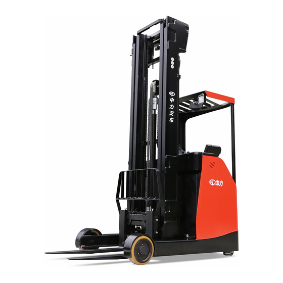
INFORMATION & SPECIFICATIONS 1.2 Introduction Name Name Lift Mast Drive Wheel Overhead Guard Seat Free Lift Cylinder Foot Switch Controller Brake Pedal Load Wheel Accelerator Pedal Reach Outrigger Battery Slider Unlocking Lever Battery Star-shaped Handle Tank Control Panel REV. 07/2016... -
Page 19: Common Tools
INFORMATION & SPECIFICATIONS This series are electric reach trucks. Its impor- tant structure is as shown in Figure 90001. WARNING - Please refer to the nameplate for rated load capacity of the vehicle. - The vehicle can only be used on the level gro- und indoors, never use it on mezzanine or balcony area. -
Page 20: General Tightening Torques
INFORMATION & SPECIFICATIONS 1.4 General Tightening Torques Screws or bolts used on the truck are of 8.8 grade or higher performance level. When you are conducting truck maintenance, you can refer to Table 1.4.1 and Table 1.4.2 to select the suitable screws or bolts for replace- ment. - Page 21 INFORMATION & SPECIFICATIONS Table 1.4.2 Metric Screws/Bolts Tightening Torque Table (n•m) Performance Level 10.9 12.9 Nominal Diameter (mm) Proof Stress (MPa) 10~12 14~17 17~20 16~18 25~30 34~41 41~48 M8×1 17~20 27~32 37~43 43~52 31~36 49~59 68~81 81~96 M10×1 35~41 55~66 76~90 90~106 55~64...
- Page 22 INFORMATION & SPECIFICATIONS REV. 07/2016...
-
Page 23: Maintenance
2. MAINTENANCE... - Page 24 NOTE:...
-
Page 25: Overview
MAINTENANCE 2.1 Overview NOTE Only by performing regular vehicle maintenance Under harsh working conditions: such as, the and repair, can ensure the continuous and external temperature is too high or too low, reliable use of the truck. dusty, or implementing multiple shifts per day, Only specially trained and qualified personnel the maintenance and care interval should be a r e c a p a b l e o f m a i n t e n a n c e a n d r e p a i r... -
Page 26: Maintenance
MAINTENANCE 2.2 Maintenance Regular inspection and maintenance under harsh conditions of use: 2.2.1 Cleaning Under harsh working conditions, especially: - Dusty environment Do not use flammable liquids to clean the - Corrosive environment truck. - Cold storage environment Before starting to clean, all necessary The maintenance intervals should be shortened security measures must be taken to prevent by half. - Page 27 MAINTENANCE Table 2.1 Inspection & Maintenance List Interval in days/months/years 60 d 90 d Interval in hours 1000 Functions and Control Check the functions of the operation switches and display Check alarm system functions Check foot switch functions Check the emergency switch functions Check the cables for damage and if the terminals are secure Check the electronic limit functions...
- Page 28 MAINTENANCE Table 2.1 Inspection & Maintenance List (Continued) Interval in days/months/years 60 d 90 d Interval in hours 1000 Power Supply & Drive System Check transmission oil level Replace after 100 hours of early operation. Clean or replace the gear oil Then replace once every 2000 hours Check the gearbox for abnormal noise or leaks Check and lubricate the bearings between drive motor...
- Page 29 MAINTENANCE Table 2.1 Inspection & Maintenance List (Continued) Interval in days/months/years 60 d 90 d Interval in hours 1000 Breking System Check the braking functions of electromagnetic brake Check the air gap of electromagnetic brake Check the installation and connection of electromagnetic brake Check the braking distance of electromagnetic brake Check the braking functions of brake...
- Page 30 MAINTENANCE Table 2.1 Inspection & Maintenance List (Continued) Interval in days/months/years 60 d 90 d Interval in hours 1000 Mast System Visual inspection of rollers, sliders and stoppers Check the lifting and lowering speed Other Check if the signs are clear and complete Check the chassis for cracks or damages Check the engine hood and lubricate the hinges A / L...
-
Page 31: Lubrication
MAINTENANCE 2.2.3 Lubrication CAUTION Lubricant The use and disposal of lubricants must be carried out in strict accordance with the manufa- Improper operations may constitute hazards cturer's regulations. to the operator's health and life, as well as to the surrounding environment. When storing or adding lubricant, use clean containers. - Page 32 MAINTENANCE Table 2.2 Lubricants Code Type Specifi cation Amount Position Anti-wear hydraulic oil L-HM46 Hydraulic See Table 2.3 Low temperature anti-wear System L-HV32 hydraulic oil (cold storage) Sliding surface Multi-purpose grease Polylub GA352P Appropriate amount (See Table 2.4) Heavy duty gear oil 80W-90 GL-5 3.3L (Align with oiling port) Gearbox After the gas within the...
- Page 33 MAINTENANCE Table 2.4 Sliding Surface Lubrication Table Code Position Steering gear Engine hood hinges Caster Load Wheel Forward tilting guides and rollers Chains Steel channel and rollers Side shifter REV. 07/2016...
- Page 34 MAINTENANCE REV. 07/2016...
-
Page 35: Structure & Functions
3. STRUCTURE & FUNCTIONS... - Page 36 NOTE:...
-
Page 37: Structure & Functions
STRUCTURE & FUNCTIONS 3.1 Structure & Functions 3.1.1 Travel Switch Location: on front cover of control panel; Function: to output travel speed signal to the drive controller; Description: when the vehicle is powered on, the travel switch is at Middle position; Note: Unserviceable. -
Page 38: Control Switch (Rvf/Nrvf)
STRUCTURE & FUNCTIONS 3.1.5 Control Switch (RVF/NRVF) Location: on front cover of control panel; Function: to provide the controller with lift - lower, forward - retract, tilt forward - tilt backward, shift left - shift right and other signal inputs; Description: when the vehicle is powered on, the travel switch is at Middle position;... -
Page 39: Fan
STRUCTURE & FUNCTIONS 3.1.9 Fan Location: at side of engine hood panel; Function: for cooling of drive systems and pump motor; Description: 48V operating voltage; Note: Unserviceable. 3.1.10 Accelerator Pedal Location: on foot switch cover; Function: to provide acceleration signal for the travel of truck;... -
Page 40: Warning Light
STRUCTURE & FUNCTIONS 3.1.13 Warning Light Location: above the overhead guard; Function: to warn the surrounding personnel that the truck is powered on, please keep clear of it; Description: 12V operating voltage; Note: Unserviceable. 3.1.14 Headlight Location: below the overhead guard; Function: to provide lighting for operator;... -
Page 41: Ac2 Controller(Trancecontroller)
STRUCTURE & FUNCTIONS 3.1.17 AC2 Controller(TranceController) Location: electrical mounting plate; Function: to control the speed of drive motor through the signal input by the accelerator; Description: 48V operating voltage, to control the drive motor circuit; Note: Unserviceable. AC2 Drive Controller 3.1.18 AC2 Controller (Pump Controller) Location: electrical mounting plate;... -
Page 42: Main Contactor
STRUCTURE & FUNCTIONS 3.1.21 Main Contactor Location: electrical mounting plate; Function: to connect and disconnect circuit and to control the power transmission of drive motor; Description: to provide power loads through controller under the circumstances that the controller is failure-free; Note: Unserviceable. -
Page 43: Pump Motor
STRUCTURE & FUNCTIONS 3.1.25 Pump Motor Location: right side of the drive motor; Function: to provide power for gear pump for lifting of carriage; Description: upon receiving the signal input by control switch, AC2 pump controller to control the power transmission of pump motor; Note: Unserviceable. - Page 44 STRUCTURE & FUNCTIONS REV. 07/2016...
-
Page 45: Chassis System
4. CHASSIS SYSTEM... - Page 46 NOTE:...
-
Page 47: Load Wheel
CHASSIS SYSTEM 4.1 Load Wheel 4.1.1 Removal and Installation Removal Lift the vehicle carefully with lifting equipment through the lifting holes at back; WARNING Make sure the lifting equipment is solid and secure, and the load capacity should be greater than the total weight of the vehicle. -
Page 48: Caster
CHASSIS SYSTEM 4.2 Caster CAUTION 4.2.1 Removal and Installation After long time of use, the drive wheel will wear and tear to certain level, at this time, adjust Removal the height of caster (2) through increasing or Lift the vehicle carefully with lifting equipment decreasing the number of adjustment shims (2) through the lifting holes at at front and back;... -
Page 49: Brake Pedal
CHASSIS SYSTEM 4.3 Brake Pedal 4.3.1 Removal and Installation Removal Unscrew the four screws used to fi x the pedal and remove the pedal; Remove the three tubings (12, 13 & 14) on brake master cylinder (2); Unscrew the three bolts (7) with wrench and remove the service brake assembly from the chassis;... -
Page 50: Faults And Causes
CHASSIS SYSTEM 4.4 Seat CAUTION 4.4.1 Removal and Installation During the entire process of operation, there must always be brake fl uid in the oil cup. Removal - Add brake fl uid into the oil cup until it fi lls 2/3 Unscrew the star-shaped handle on engine of the cup. -
Page 51: Brakes
CHASSIS SYSTEM 4.5 Brakes Installation - Install according to the reverse order of rem- 4.5.1 Removal and Installation oval; Removal Adjustment Remove the load wheel; (see Section 4.1.1) Unscrew the four screws (1), loosen the - Toggle the toothed fl ange on the lash adjuster connection between the brake (2) and the with slotted screwdriver through the opening chassis;... -
Page 52: Faults And Causes
CHASSIS SYSTEM Air Discharge / Adding Brake Fluid Unscrew the star-shaped handle on engine hood and open the engine hood; Fill the oil cup with brake fl uid; Press the brake pedal repeatedly until the stepping pressure becomes heavy; Open the vent on brake cylinder of drum brake, press the brake pedal pressure to the bottom, discharge the residual air from the vent through high level of brake fl... -
Page 53: Drive System
5. DRIVE SYSTEM... - Page 54 NOTE:...
- Page 55 DRIVE SYSTEM Drive System Name Name Drive Wheel Gearbox Electromagnetic Brakes Steering Motor Drive Motor Proximity Switch Large Steering Bearing Pinion Gear Large Ring Gear Drive Mounting Base REV. 07/2016...
-
Page 56: Drive Wheel
DRIVE SYSTEM 5.1 Drive Wheel 5.1.1 Removal and Installation Removal Lift the vehicle carefully with lifting equipment through the lifting holes at at front and back; WARNING Make sure the lifting equipment is solid and secure, and the load capacity should be greater than the total weight of the vehicle.Lifting height of not more than 300mm, to prevent the hazards to the maintenance personnel working under... -
Page 57: Electromagnetic Brakes
DRIVE SYSTEM 5.2 Electromagnetic Brakes 5.2.1 Removal and Installation Removal The truck is braked through electromagnetic brake. When the truck is powered off, the The brake is installed on the drive motor. See electromagnetic coil (6) doesn't absorb the Figure 90204 pressure plate (8), the friction force generated between brake pads (2), pressure plate and friction plates (5) will prevent the drive motor... -
Page 58: Faults And Causes
DRIVE SYSTEM Installation After the coil is powered off, the Fault pressure plate won't release - Install according to the reverse order of rem- oval; Cause Foreign body blocking Fault Abnormal noise after absorption CAUTION a. Fully absorbed, but plate not When installing the brake gear (7), make sure Cause fl... -
Page 59: Control Circuit Troubleshooting
DRIVE SYSTEM Air Gap Checks Check if there is foreign body in the air gap that may affect the absorption or bouncing off of the Switch off the truck power connections and pressure plates. pull out the brake connectors; Check the air gap between electromagnetic Spring Checks coil and pressure plate with feeler gauge: measurement method is as shown in Figure... -
Page 60: Drive Motor
DRIVE SYSTEM 5.3 Drive Motor Installation - Install according to the reverse order of rem- This truck obtains drive force through AC motor. oval; Temperature CAUTION Sensor When installing the motor gear of gearbox onto the shaft of the motor, make sure that Speed Encoder the woodruff key on the motor shaft is fully seated on the motor gear;... -
Page 61: Checking And Testing
DRIVE SYSTEM - Identify if there is leakage current through Motor temperature too high, Fault measuring the resistance between U, V, W controller failure and motor housing respectively. a. Stator winding short circuit; as shown in the following table: b. Motor U, V and W terminals with Resistance surface ;... -
Page 62: Control Circuit Troubleshooting
DRIVE SYSTEM Speed Encoder Speed encoder is used to detect the speed of the motor and covert the speed into fixed signals. Checking - Check if the motor encoder and the appear- ance of cables are in good condition, and if the plug connection is secure. -
Page 63: Gearbox
DRIVE SYSTEM 5.4 Gearbox CAUTION 5.4.1 Removal and Installation Before installing the new gearbox, please add gear oil (see Section 2.2.3 for specification Removal and fi lling amount); The gearbox is installed under the drive mount- Before installing gearbox, remove the proxi- ing base. -
Page 64: Proximity Switch
DRIVE SYSTEM 5.5 Proximity Switch 5.5.1 Removal and Installation Removal Proximity switch is installed on the drive mount- ing base. Pull out the AMP connector on proximity swit- Loosen Nut (1) and unscrew the proximity switch. NOTE Installation Failure: Steering positioning failed, drive wheel keeps rotating with system error, and fault information is displayed on the meter (Fault Code 238 EPS NOT ALIGNED). -
Page 65: Checking And Testing
DRIVE SYSTEM 5.5.3 Checking and Testing - Check if the inductive distance is normal, if exceeding inductive range, please re-adjust (see 5.5.2). Brown Blue Black Testing Start the vehicle; Align the inductive surface of proximity switch (2, Figure 90215) to concave of big ring gear, so that it does not sense. -
Page 66: Steering Motor
DRIVE SYSTEM 5.6 Steering Motor Speed Encoder Removal This truck is driven by AC steering motor to the large ring gear, thus achieving the function of Switch off the truck power connections; steering. Pull out the AMP connector on the speed encoder (2, Figure 50224);... -
Page 67: Checking And Testing
DRIVE SYSTEM - Identify if there is leakage current through Fault Motor smoking or burning smell measuring the resistance between U, V, W Stator winding short circuit, motor and motor housing respectively. Cause burnt as shown in the following table: Motor temperature too high, Resistance Fault... -
Page 68: Control Circuit Troubleshooting
DRIVE SYSTEM Speed Encoder The vehicle is powered on, measure the voltage between pin connector (80#) and Speed encoder is used to detect the speed (83#) with a multimeter, normally should be of the motor and covert the speed into fixed signals. -
Page 69: Operating System
6. OPERATING SYSTEM... - Page 70 NOTE:...
-
Page 71: Control Lever
(warning light and wheel (1); headlights), travel switch, key switch, control Unscrew the screw (4), remove the top cover switch (configuration of CQD16/20 (N) RVF (6) and bottom cover (5) from operating model), emergency stop switch, horn button handle (7);... -
Page 72: Horn Button
OPERATING SYSTEM 6.3 Horn Button 6.3.3 Checking and Testing Push button switch is the switch that makes Checking the dynamic and static contacts ON or OFF to - Check if the pushbutton switch and the achieve the switching of circuits through push- appearance of cables are in good condition, button drive mechanism. -
Page 73: Control Switch (Rvf/Nrvf)
OPERATING SYSTEM 6.4 Control Switch (RVF/NRVF) Testing Enter the TESTER Menu to check the status Control switch will provide the vehicle with of switches: toggle each control switch Lifting / Lowering, Forward / Retract, Tilting separately to check the ON/OFF status. If the Forward / Tilting Backward, Left Shifting / Right display does not change, it indicates there is Shifting and other signal inputs. -
Page 74: Control Circuit Troubleshooting
OPERATING SYSTEM 6.4.4 Control Circuit Troubleshooting Lift - Lower Switch Control Circuit (Figure 90305) Check if the circuit is broken by using a multi- meter: Set the multimeter to ON-OFF; Check if #5/#6/#8/#9 circuit (circuit between control switch and instruments) is conducted. Forward Shifting - Retract Switch Control Circuit (Figure 90306) Check if the circuit is broken by using a multi-... - Page 75 OPERATING SYSTEM Forward Tilting – Backward Tilting Switch Control Circuit (Figure 90307) Check if the circuit is broken by using a multi- meter: Set the multimeter to ON-OFF; Check if #10/#11/#12/#13 circuit (circuit bet- ween control switch and instruments) is con- ducted.
-
Page 76: Control Switch (Rv/Nrv)
OPERATING SYSTEM 6.5 Control Switch (RV/NRV) Control switch will provide the vehicle with input signals for starting the pump motor. See Section 3.1 for mounting positions of contr- ol switch. Normally-open (N0): Terminal (1) and Terminal (3) for connection of wiring harness connector to switch base. -
Page 77: Control Circuit Troubleshooting
OPERATING SYSTEM 6.5.5 Control Circuit Troubleshooting Lift Switch Control Circuit (Figure 90318) Check if the circuit is broken by using a multi- meter: Set the multimeter to ON-OFF; Check if #7/#8 circuit (circuit between control switch and instruments) is conducted. Forward Shifting - Retract Switch Control Circuit (Figure 90319) Check if the circuit is broken by using a multi-... - Page 78 OPERATING SYSTEM Forward Tilting – Backward Tilting Switch Control Circuit (Figure 90320) Check if the circuit is broken by using a multi- meter: Set the multimeter to ON-OFF; Check if #10/#11 circuit (circuit between control switch and instruments) is conducted. Left Shifting –...
-
Page 79: Stepper Motor
OPERATING SYSTEM 6.6 Stepper Motor Black Blue White Stepper motor provides the vehicle with steering input signals. 6.6.1 Removal and Installation See Section 6.1 . 6.6.2 Faults and Causes Operate the steering wheel, the “STEPPER MOTOR”, turn the steering wheel, vehicle does not respond to the if the voltage display is always "0", it indicates Fault... -
Page 80: Key Switch
OPERATING SYSTEM 6.7 Key Switch 6.7.3 Checking and Testing Key switch is used to START / STOP the truck. Checking - Check if the appearance of key switch its wiring harness are in good condition, and if 6.7.1 Removal and Installation the connectors are connected securely. -
Page 81: Emergency Switch
OPERATING SYSTEM 6.8 Emergency Switch 6.8.3 Checking and Testing Emergency switch is used for emergency cut-off Checking of the power supply to all the control circuits. - Check if the appearance of emergency switch its wiring harness are in good condition, and if the connectors are connected securely. -
Page 82: Rocker Switch
OPERATING SYSTEM 6.9 Rocker Switch 6.9.3 Checking and Testing The rocker switch of this truck is used to control Checking the ON/OFF of headlights and warning light. - Check if the appearance of rocker switch is in The rocker switch is classifi ed by functions as: good condition, and if the plug connection is Headlight Switch and Warning Light Switch secure. - Page 83 OPERATING SYSTEM Warning Light Switch Control Circuit (Figure 90314) Check if the circuit is broken by using a multi- meter: Set the multimeter to ON-OFF; Check if #93 circuit (circuit between switch and converter) is conducted; Check if #95 circuit (circuit between switch and warning light) is conducted;...
-
Page 84: Travel Switch
OPERATING SYSTEM 6.10 Travel Switch 6.10.3 Checking and Testing Drive switch provides forward or backward input Checking signals for the vehicle. - Check if the appearance of travel switch is in good condition, and if the plug connection is secure. 6.10.1 Removal and Installation Testing See Section 6.2 . -
Page 85: Hydraulic System
7. HYDRAULIC SYSTEM... - Page 86 NOTE:...
-
Page 87: Overview
HYDRAULIC SYSTEM The system pressure of the entire hydraulic Hydraulic Oil system pressure is provided by hydraulic power Hydraulic oil for truck: unit system, which is used for lifting. While the Specifi cations: Anti-wear Hydraulic Oil L-HM46. hydraulic power unit is equipped with a relief valve to ensure that the entire system pressure * For cold storage: Low Temperature Anti-wear is always within the safety limits that can lift the... -
Page 88: Hydraulic Schematic Diagram Rvf/Nrvf
HYDRAULIC SYSTEM 7.1.1 Hydraulic Schematic Diagram RVF/NRVF REV. 07/2016... -
Page 89: Hydraulic Schematic Diagram Rv/Nrv
HYDRAULIC SYSTEM 7.1.2 Hydraulic Schematic Diagram RV/NRV REV. 07/2016... -
Page 90: Hydraulic Power Unit
HYDRAULIC SYSTEM 7.2 Hydraulic Power Unit 7.3 Pump Motor 7.2.1 Removal and Installation This truck obtains hydraulic power through the AC pump motor. Speed Encoder Temperature Sensor 7.3.1 Removal and Installation See Section 7.2.1 . Removal Open the engine hood; 7.3.2 Faults and Causes Remove the AMP connector on the pump motor and pump motor and carry out the fol-... -
Page 91: Checking And Testing
HYDRAULIC SYSTEM - Identify if there is leakage current through Motor temperature too high, Fault measuring the resistance between U, V, W controller failure and motor housing respectively. a. Stator winding short circuit; as shown in the following table: b. Motor U, V and W terminals with Resistance surface ;... -
Page 92: Control Circuit Troubleshooting
HYDRAULIC SYSTEM Speed Encoder Speed encoder is used to detect the speed of the motor and covert the speed into fixed signals. Checking - Check if the motor encoder and the appear- ance of cables are in good condition, and if the plug connection is secure. -
Page 93: Multi-Way Reversing Solenoid Valve (Rvf/Nrvf)
HYDRAULIC SYSTEM 7.4 Multi-way Reversing Solenoid Installation Valve (RVF/NRVF) - Install according to the reverse order of rem- The ON/OFF of tubing within the valve chamber oval. is controlled through solenoid valve, thus to control the Lifting - Lowering, Forward Shifting - CAUTION Retract, Tilting Forward - Tilting Backward and As some hydraulic oil will be lost when... -
Page 94: Faults And Causes
HYDRAULIC SYSTEM 7.4.3 Faults and Causes 7.4.5 Control Circuit Troubleshooting Solenoid Valve Control Circuit The vehicle cannot perform the Fault (Figure 90409) hydraulic control instructions a. Solenoid valve failure; Check if the circuit is broken by using a multi- b. Insuffi cient power supply meter: voltage;... -
Page 95: Solenoid Valve (Rvf/Nrvf)
HYDRAULIC SYSTEM 7.5 Solenoid Valve (RVF/NRVF) Fault Internal leakage When solenoid valve coil is energized (there Damaged seals or spring Cause is voltage between coil end A and B), the deformations electromagnetic coil generates electromagnetic Fault External leakage force, and the spool will move, the valve will open, and the vehicle will be lowered. -
Page 96: Control Circuit Troubleshooting
HYDRAULIC SYSTEM - Remove the solenoid valve, take out the spool and spool sleeve, clean with CCI4 to enhance the fl exibility of the moving of spool within the spool sleeve. During disassembly, pay attention to the sequence of assembly and position of external wiring for correct re- assembly and wiring, also check the oil mist spray orifi... -
Page 97: Multi-Way Reversing Manual Valve (Rv/Nrv)
HYDRAULIC SYSTEM 7.6 Multi-way Reversing Manual Valve Remove the tubing on multi-way valve (1) and wiring harness on control switch (12); (RV/NRV) Remove the cotter pin on pin shaft (3), The valve rod is driven by lever to switch the ON remove the connecting rod (4) between multi- and OFF of tubing within the valve body, thus to way valve and control lever;... -
Page 98: Interface Description
HYDRAULIC SYSTEM 7.6.2 Interface Description 7.6.3 Faults and Causes The vehicle cannot perform the Fault hydraulic control instructions a. Valve failure; b. Valve seat blocked by large impurities; c. External leakage: sealing damaged; Cause poor threaded connection; valve body defects; d. -
Page 99: Gear Pump
HYDRAULIC SYSTEM 7.7 Gear Pump Fault Oil leaks a. Pump body defects; Cause b. Seal skeleton spring off; c. Shaft sealing surface scratched. Oil Outlet Pump is not functioning properly or Fault blocked a. Pump body defects; b. Pressure valve malfunction; Cause c. -
Page 100: Reach Cylinder
HYDRAULIC SYSTEM 7.8 Reach Cylinder Upon removal, the damage to cylinder threads, oil port threads, cylinder cap threads, 7.8.1 Cylinder Removal Precautions piston rod surface and inner cylinder wall should be prevented. Before removing the cylinder, be sure to reli- In order to prevent piston rod from bending or eve the hydraulic circuit fi... -
Page 101: Cylinder Installation Precautions
HYDRAULIC SYSTEM CAUTION Cylinder Cap O-ring is quite flexible and easy to install, but it must not be pulled up to the extent of permanent deformation, nor scroll it while installing; Y-ring or X-ring needs to be identifi ed if it is Cylinder Wrenches for shaft or hole to avoid misplacement;... -
Page 102: Removal And Installation
HYDRAULIC SYSTEM 7.8.3 Removal and Installation Unscrew the anchor bolt (4) underneath the forward shift mast with socket wrench and Cylinder is installed on the chassis and forward pull out the pin shaft (5); shift mast.(See Figure 90415) Remove the forward tilt cylinder (3); Shift the mast forward, block the truck wheel Replace with new cylinder and install in rever- with a wooden wedge, press the emergency... -
Page 103: Cylinder Maintenance
HYDRAULIC SYSTEM 7.8.4 Cylinder Maintenance Remove the sleeve (15) and remove the two O-rings (3) inside it; Remove the cylinder cap (5) and remove its CAUTION dust ring (2), O-rings (3), seal (4), O-ring (6) Use suitable hose clamps to avoid cylinder and O-ring (16);... -
Page 104: Hydraulic Troubleshooting
HYDRAULIC SYSTEM 7.9 Hydraulic Troubleshooting Fault Symptom Failure Causes Troubleshooting Measures a. Insuffi cient oil; 1. Check the hydraulic oil level. b. High viscosity of oil; 2. Replace the hydraulic oil. c. Oil suction pipe air leak; 3. Check the oil suction pipe. Noisy pump d. -
Page 105: Hydraulic Symbol
HYDRAULIC SYSTEM 7.10 Hydraulic Symbol Symbol Description Symbol Description Tank Pipe end below liquid Explosion-proof valve level Tank Pipe end above liquid Check valve level Cylinder Filter Single-acting direction Service line Cylinder (Supply line or return D o u b l e - a c t i n g line) direction Control line... - Page 106 HYDRAULIC SYSTEM REV. 07/2016...
-
Page 107: Electrical System
8. ELECTRICAL SYSTEM... - Page 108 NOTE:...
-
Page 109: Controller
ELECTRICAL SYSYTEM 8.1 Controller Controller: traction controller: mainly used for the control Controller Functions of drive motor Electrical control of this truck is mainly driven Pump controller: mainly used for the control by controller, pump controller and steering of pump motor controller. - Page 110 ELECTRICAL SYSYTEM Unscrew the four screws (3) with a wrench and remove the pump controller (4); Unscrew the four screws (5) with a wrench and remove the solenoid valve controller (6); Unscrew the four screws (7) with a wrench and remove the steering controller (8). Installation Apply appropriate amount of thermal grease on the back of controller;...
-
Page 111: Controller Interface Function
ELECTRICAL SYSYTEM 8.1.2 Controller Interface Function Traction Controller (AC2-TRACTION) A Interface (handheld unit communication interface) Pin No. Signal Name Description PCLRXD Positive serial reception. NCLRXD Negative serial reception. PCLTXD Positive serial transmission. NCLTXD Negative serial transmission. Negative console power supply. +12V Positive console power supply. - Page 112 ELECTRICAL SYSYTEM D Interface Pin No. Signal Name Description positive of encoder power supply. +5V/+12V negative of encoder power supply. phase A of encoder. phase B of encoder. E Interface Pin No. Signal Name Description CPOT Accelerator Pedal Enabling Switch Input. PPOT Accelerator Pedal Positive Electrode.
- Page 113 ELECTRICAL SYSYTEM Pump Controller (AC2-PUMP) A Interface (handheld unit communication interface) Pin No. Signal Name Description PCLRXD Positive serial reception. NCLRXD Negative serial reception. PCLTXD Positive serial transmission. NCLTXD Negative serial transmission. Negative console power supply. +12V Positive console power supply. It must be connected to A8 for the Flash memory FLASH programming.
- Page 114 ELECTRICAL SYSYTEM C Interface Pin No. Signal Name Description Low level CAN-BUS voltage I/O. CAN-L Connected to traction controller. Low level CAN-BUS voltage I/O. CAN-L-OUT Connected to solenoid valve controller (RVF/NRVF); Connected to steering controller(RV/NRV). High level CAN-BUS voltage I/O. CAN-H Connected to traction controller.
- Page 115 ELECTRICAL SYSYTEM Steering Controller (EPS-AC0) A Interface Pin No. Signal Name Description 2nd Toggle Switch. 1st Toggle Switch. Safety Switch Lower Voltage Point. Safety Switch Higher Voltage Point. Can Bus Low. CANL Connected to solenoid valve controller (RVF/NRVF); Connected to pump controller(RV/NRV). Key Switch Signal Input Port.
- Page 116 ELECTRICAL SYSYTEM B Interface Pin No. Signal Name Description Motor Thermal Sensor (KTY84-130) Input. THMOT Encoder Positive Supply. +5VDC phase B of encoder. phase A of encoder. C Interface (handheld unit communication interface) Pin No. Signal Name Description PCLRXD Positive serial reception. NCLRXD Negative serial reception.
- Page 117 ELECTRICAL SYSYTEM Instrument (SICOS) A Interface Pin No. Signal Name Description Safety pedal communication interface, connected to traction controller. A#14 Seat Switch Signal Input Port. A#16 Seat Switch - Positive Electrode, +48V. B Interface (RVF/NRVF) Pin No. Signal Name Description Lifting / Lowering Signal Input Port.
- Page 118 ELECTRICAL SYSYTEM B Interface (RV/NRV) Pin No. Signal Name Description Lifting Signal Input Port. Side Shift Signal Input Port. Side Shift - Positive Electrode, +5V. Lifting - Negative Electrode. C Interface (RVF/NRVF) Pin No. Signal Name Description Tilting Signal Input Port. Tilting Potentiometer Sliding Access Port.
- Page 119 ELECTRICAL SYSYTEM Solenoid Valve Controller (MHYRIO FLASH) RVF/NRVF A Interface Pin No. Signal Name Description Reset Switch Signal Input Port. Forward Shifting Limit Switch Signal Input Port. I3/I5 Positive Electrode. A#10 CANH Can Bus High.Connected to pump controller. A#22 CANL Can Bus Low.Connected to pump controller.
- Page 120 ELECTRICAL SYSYTEM G Interface Pin No. Signal Name Description NEV8 Backward Tilting Solenoid Valve Coil - Negative Electrode. NEV7 Forward Tilting Solenoid Valve Coil - Negative Electrode. NEV6 Left Shifting Solenoid Valve Coil - Negative Electrode. NEV5 Right Shifting Solenoid Valve Coil - Negative Electrode. NEV4 Retracting Solenoid Valve Coil - Negative Electrode.
-
Page 121: Fuse
ELECTRICAL SYSYTEM 8.2 Fuse The entire vehicle is installed with three fuses altogether. When there is fuse failure, the truck may not be able to run properly due to that. Status Function Fuse 1 Fuse 2 Fuse 3 Fuse 1 300A ×... -
Page 122: Checking And Testing
ELECTRICAL SYSYTEM 8.2.2 Checking and Testing Checking - Check the fuses for damage, check the connectors at terminal lugs for loosening or poor connection of leads. Testing Turn the key switch to "OFF", remove key; pull out the battery plug and disconnect the power supply. -
Page 123: Main Contactor
ELECTRICAL SYSYTEM 8.3 Main Contactor This truck is using dual contactors with normally-open contacts. And the ON/OFF of the contactors is controlled through controller, thus to achieve the control of ON/OFF of the vehicle. When the contactor coil is energized, the coil current will create a magnetic fi... -
Page 124: Checking And Testing
ELECTRICAL SYSYTEM 8.3.3 Checking and Testing Visual Inspection Check the surface and appearance of contac- tor; Visually check the surface of contactor for scratches, damages and stains; If any of the above case is found, please replace with new contactor. Coil Checks Disconnect the cables on the contactor;... -
Page 125: Height Display (Rvf/Nrvf)
ELECTRICAL SYSYTEM 8.4 Height Display (RVF/NRVF) CAUTION RVF/NRVF premium grade truck model can Make sure the lifting equipment is solid and select the optional height display function. This secure, and the load capacity should be greater function is primarily achieved through height than the total weight of the vehicle, so that encoder (5), steel wire rope (7), reset switch (9) to prevent the maintenance personnel from... -
Page 126: Control Circuit Troubleshooting
ELECTRICAL SYSYTEM Testing - The vehicle is powered on, measure the volt- age between pin connector (88#) and (91#) with a multimeter, normally should be 12V. 8.4.4 Control Circuit Troubleshooting Height Display Control Circuit (Figure 90513) Check if the circuit is broken by using a multi- meter: Set the multimeter to ON-OFF;... -
Page 127: Limit Switch
ELECTRICAL SYSYTEM 8.5 Limit Switch - Re-install the switch cover (3) onto the switch seat (2) and tighten the fi xing screws (1). CAUTION When installing waterproof rubber ring, make sure it is fully seated in the mounting slot of the switch seat. -
Page 128: Faults And Causes
ELECTRICAL SYSYTEM 8.5.3 Faults and Causes Testing Enter TESTER Menu to check if each limit Reset Switch (RVF/NRVF) switch is working properly; (see Section 8.12) Turn the key switch to "OFF", remove key; The mast is not lifted, but the instr- Fault pull out the battery plug and switch off the ument reading of height is not 0... - Page 129 ELECTRICAL SYSYTEM Lifting Speed Reduction Switch Control Circuit (Figure 90515) Check if the circuit is broken by using a multi- meter: Set the multimeter to ON-OFF; Check if #103/#104 circuit (circuit between lifting speed reduction switch and pump con- troller) is conducted. REV.
-
Page 130: Accelerator Pedal
ELECTRICAL SYSYTEM 8.6 Accelerator Pedal 8.6.2 Faults and Causes 8.6.1 Removal and Installation Press the accelerator pedal, Fault operate travel switch, the vehicle Removal cannot go forward or backward See Section 3.1 for mounting position of acce- a. Accelerator pedal failure; lerator pedal. -
Page 131: Control Circuit Troubleshooting
ELECTRICAL SYSYTEM - Check if the accelerator pedal and its wiring - Press the accelerator pedal. Measure harness are in good condition, and if the the voltage between the interfaces with a connectors are connected securely. multimeter. as shown in the following table: Testing Press the accelerator pedal Enter TESTER Menu through instrument... -
Page 132: Foot Switch
ELECTRICAL SYSYTEM 8.7 Foot Switch 8.7.2 Faults and Causes 8.7.1 Removal and Installation Foot switch not pressed, the vehic- Fault le can still travel or lift (foot switch Removal indicator on the instrument is off) See Section 3.1 for mounting position of foot a. -
Page 133: Control Circuit Troubleshooting
ELECTRICAL SYSYTEM 8.7.4 Control Circuit Troubleshooting Foot Switch Control Circuit (Figure 90517) Check if the circuit is broken by using a multi- meter: Set the multimeter to ON-OFF; Check if #27/#30 circuit (circuit between foot switch and drive controller) is conducted. REV. -
Page 134: Dc-Dc Converter
ELECTRICAL SYSYTEM 8.8 DC-DC Converter 8.8.3 Checking and Testing DC-DC converter provides converted voltage Checking for warning light and headlights. - Check if the appearance of converter and its Working performance: 48V DC to 12V wiring harness are in good condition, and if the connectors are connected securely. -
Page 135: Warning Light / Headlight
ELECTRICAL SYSYTEM 8.9 Warning Light / Headlight 8.9.3 Checking and Testing This truck is installed with one warning light and Checking two headlights on overhead guard. - Check if the appearance of warning light See Section 3.1 / headlight and its wiring harness are in good condition, and if the connectors are connected securely. -
Page 136: Cooling Fan
ELECTRICAL SYSYTEM 8.10 Cooling Fan 8.10.3 Checking and Testing This truck has two cooling fans, one is installed Checking on the side of engine hood, the other is installed Check the cooling fan for blockage of foreign under the cooling aluminum plate of controller. bodies;... - Page 137 ELECTRICAL SYSYTEM Fan (at Controller) Control Circuit (Figure 90527) Check if the circuit is broken by using a multi- meter: Set the multimeter to ON-OFF; Check if the #3/#105 circuit (circuit between fan and pump controller) is conducted. Emergency Switch Key Switch REV.
-
Page 138: Seat Switch
ELECTRICAL SYSYTEM 8.11 Seat Switch 8.11.3 Checking and Testing Seat switch is mounted under the seat. Checking Check if the appearance of seat switch and its wiring harness are in good condition, and 8.11.1 Removal and Installation if the connectors are connected securely; Removal Repeatedly press the seat switch to check if it can reset properly. -
Page 139: Instrument
ELECTRICAL SYSYTEM 8.12 Instrument Foot Switch OK / ENTER button Display Area Hydraulic action Speed model Power capacity PageUp button display area display area display area EXIT button PageDown button Running time Steering display Height display Number display area area area buttons Fault display... - Page 140 ELECTRICAL SYSYTEM TESTER MASTER Menu NOTE mainmenu1 : Not running TESTERMASTER : Running TESTERSLAVES ALARMS tester 1 Description PROGRAMOFFSET INSERTPASSWORD Check forward switch Check backward switch Check accelerator enabling switch Check seat switch tester1 Check the foot switch Check lifting speed reduction switch Check the reset switch Check lifting - lowering switch Check forward shift - retracting switch...
- Page 141 ELECTRICAL SYSYTEM TESTER SLAVES Menu mainmenu1 TESTERMASTER TESTERSLAVES NOTE ALARMS PROGRAMOFFSET tester 1 Description INSERTPASSWORD Check the current of CURRENT TRACTION drive motor Check the voltage of VOLTAGE TRACTION drive motor tester1 Check the speed of CURRENTTRACTION=000AMP. FREQUENCY TRAC. VOLTAGETRACTION=009% drive motor FREQUENCYTRAC.=000HERZ Check the temperature...
- Page 142 ELECTRICAL SYSYTEM ALARMS Menu mainmenu1 TESTERMASTER TESTERSLAVES ALARMS PROGRAMOFFSET INSERTPASSWORD NOTE Code Description ALARMS1HOURSNUMNTCMOD Fault information ALARMS 1 1)******0000002271 2)******0000012272 Runtime of the most recent failure HOURS 3)******0000003276 Number of the same fault occurs 4)******0000002271 5)******0000007275 Controller temperature upon the malfunction Fault alarm controller model: 1 = Instrument (SICOS controller)
-
Page 143: Handheld Unit (Optional)
ELECTRICAL SYSYTEM 8.13 Handheld Unit (Optional) 8.13.2 Handheld Unit Menu Options Handheld unit must be used together with con- 启动 Start troller, if necessary, it can be purchased from our company or dealer. *CONSAFGZP100* RS232CONSOLE CAN CONSOLE AUTOSCANCAN Display CONSOLEUTILITIES MENUCONSOLE 09:10 Power button Navigation... - Page 144 ELECTRICAL SYSYTEM Previous Page *MAINMENU* PARAMETER CHANGE TESTER ALAARMS PROGRAMVACC SAVEPARAMETERS RESTOREPARAMETERS SETMODEL With Navigator keys (Figure 80513), you can carry out menu switching; “OK”, select ENTER the menu. PARAMETER CHANGE : parameter change TESTER : vehicle running test ALARMS : error alrms PROGRAM VACC : accelerator match SAVE PARAMETERS...
-
Page 145: Tester Menu
ELECTRICAL SYSYTEM 8.13.3 TESTER Menu The parameters in TESTER Menu are real- time presentation of the running status of the equipment. Traction / Pump Controller (AC2) Parameters Description Remark BATTERY VOLTAGE Check the voltage of storage battery Display the current voltage ( V ) STEER ANGLE Check the drive wheel angle Display the current angle ( °... - Page 146 ELECTRICAL SYSYTEM Steering Controller (EPS-AC0) Parameters Description Remark STEPPER MOTOR Check the voltage of stepper motor Display the current voltage ( V ) READ FBPT AT SW1 SET POINT POT. TRUCK SPEED SLOPE PEAK WHEEL ANGLE Check the drive wheel angle Display the current angle ( °...
-
Page 147: Controller Error Message
ELECTRICAL SYSYTEM 8.14 Controller Error Message code (see Chapter 9 - Troubleshooting); while the when the components failures which may Electrical faults are mainly caused by electrical affect the ON/OFF of control circuit occur to components failure or electrical circuit failure. the electrical circuit, the controller will alarm for Wherein, when some components failures error, and fault information will be displayed on... - Page 148 ELECTRICAL SYSYTEM Possible cause Fault elimination Error Message When the key is switched ON, the inverter tries to charge the capacitor through a power resistance, and check if the capacitor are charged within a timeout. If this is not true: an alarm is signalled; the CAPACITOR main contactor is not closed.
- Page 149 ELECTRICAL SYSYTEM Possible cause Fault elimination Error Message This is a warning. It is an information for CHECK UP the user that the programmed time for NEEDED maintenance is elapsed. - COIL SHORTED When the key is switched ON the μP checks the MC driver FF SR.
- Page 150 ELECTRICAL SYSYTEM Possible cause Fault elimination Error Message Inverter temperature is greater than 75 °C. The maximum current is reduced proportionally to the temperature increase. The inverter stops at 100 °C. HIGH Troubleshooting,the alarm is If the alarm is signalled when the inverter TEMPERATURE eliminated.
- Page 151 ELECTRICAL SYSYTEM Possible cause Fault elimination Error Message DATA This alarm is signalled in the current gain Wait the end of the acquisition activity. ACQUISITION acquisition phase. The diagnosis of the CAN-BUS line is present only if the inverter uses this link First of all, check the wiring.
-
Page 152: Steering Controller (Eps-Aco)
ELECTRICAL SYSYTEM 8.14.2 Steering Controller (EPS-ACO) Error Message Possible cause Fault elimination Error text Error M a i n u C a n d S l a v e u C communicate via a local serial interface. This alarm occurs when It is necessary to replace SERIAL ERR #1 the slave uC does not receive the... - Page 153 ELECTRICAL SYSYTEM Error Message Possible cause Fault elimination Error text Error This alarm occurs two ways: 1) In the initial rest state after key on, if the outputs of the current amplifi ers are not comprised in the It is necessary to replace STBY I HIGH window 2.2 to 2.8 Vdc.
- Page 154 ELECTRICAL SYSYTEM Error Message Possible cause Fault elimination Error text Error Check the power fuse is OK. Check the battery positive This alarm occurs when the current arrives to the controller. in the phase W of the motor is zero Check the continuity of POWER FAILURE #1 and the motor is commanded for...
- Page 155 ELECTRICAL SYSYTEM Error Message Possible cause Fault elimination Error text Error I t o c c u r s w h e n t h e e n c o d e r counting of the main uC is not It is necessary to replace MICRO SLAVE #8 matched with the encoder counting...
- Page 156 ELECTRICAL SYSYTEM Error Message Possible cause Fault elimination Error text Error This alarm occurs if the feedback potentiometer (CPOT on CNB#6) changes with a jerk larger than 0.3 C h a n g e t h e f e e d b a c k JERKING FB POT V in 16 msec.
- Page 157 ELECTRICAL SYSYTEM Error Message Possible cause Fault elimination Error text Error Check the potentiometer connected to CNB#6 is right working. If toggle switches are connected to CNA#2 and CNA#3, verify they are right working and the setting AUX FUNCTION 11 is correct. Verify also This alarm occurs for an error in the sensor bearing in the POSITION ERROR...
- Page 158 ELECTRICAL SYSYTEM Error Message Possible cause Fault elimination Error text Error Check the continuity of the This alarm occurs when the mean stepper motor connections. voltage on the Quadrature line In particular the resistance of the stepper motor (connection between CNA#8 and the Q LINE SENSOR KO CNA#8) is not null: the voltage on minus battery (with the...
- Page 159 ELECTRICAL SYSYTEM Error Message Possible cause Fault elimination Error text Error This alarm occurs only when the setting CAN BUS is PRESENT. C h e c k t h e C A N B u s Then the eps-ac0 must receive the communication system and CAN BUS KO event messages from the traction...
- Page 160 ELECTRICAL SYSYTEM Error Message Possible cause Fault elimination Error text Error This alarm occurs if the connection CNA#5 (K1) is around a voltage of 12 Vdc when switching on the key. This alarm occurs at key on if the In fact, when the safety slave uC detects the safety contact, KM CLOSED contacts are open, K1 is...
-
Page 161: Sicos Controller
ELECTRICAL SYSYTEM 8.14.3 SICOS Controller Error Message Fault elimination VACC NOT OK Accelerator high at stand or not correctly programmed POT #1 NOT OK Lifting pot high at stand or not correctly programmed POT #2 NOT OK Reach pot high at stand or not correctly programmed POT #3 NOT OK tilting pot high at stand or not correctly programmed POT #4 NOT OK... -
Page 162: Solenoid Valve Controller
ELECTRICAL SYSYTEM 8.14.4 Solenoid Valve Controller Error Message Fault elimination Error text Error Fault in the area of memory where the adjustment parameters are stored.This Alarm inhibits machine operation. If the fault continues EEPROM KO when the Key Switch is re-cycled, replace the logic. If the fault disappears, the previously stored Parameters will have been replaced by the default parameters. -
Page 163: Electrical Schematic Diagrams Rvf/Nrvf
ELECTRICAL SYSYTEM 8.15 Electrical Schematic Diagrams RVF/NRVF 8.15.1 Electrical Schematic Diagram RVF/NRVF (1/6) Emergency Switch Switch Horn Horn Switch Warning Light Headlight REV. 07/2016... -
Page 164: Electrical Schematic Diagram Rvf/Nrvf (2/6)
ELECTRICAL SYSYTEM 8.15.2 Electrical Schematic Diagram RVF/NRVF (2/6) TILT& REACH LIFT SIDE SHIFT R LIFT LOWER REACH TILT& SIDE SHIFT L LOWER BACK REACH EN FORW LIFT/LOWER EN LIFT/LOWER POT REACH POT TILT EN SEAT SW TILT POT SIDE SHIFT POT SIDE SHIFT EN REV. -
Page 165: Electrical Schematic Diagram Rvf/Nrvf (3/6)
ELECTRICAL SYSYTEM 8.15.3 Electrical Schematic Diagram RVF/NRVF (3/6) ACCELERATOR SW ACCELERATOR TEMP SENSOR EM-BRAKE REV. 07/2016... -
Page 166: Electrical Schematic Diagram Rvf/Nrvf (4/6)
ELECTRICAL SYSYTEM 8.15.4 Electrical Schematic Diagram RVF/NRVF (4/6) TEMP SENSOR SPEED RED REV. 07/2016... -
Page 167: Electrical Schematic Diagram Rvf/Nrvf (5/6)
ELECTRICAL SYSYTEM 8.15.5 Electrical Schematic Diagram RVF/NRVF (5/6) LOWER ENCODER REACH OUT REACH IN TILT&LOWER TILT&LIFT SIDE SHIFT R SIDE SHIFT L SPEED RED LIFT REV. 07/2016... -
Page 168: Electrical Schematic Diagram Rvf/Nrvf (6/6)
ELECTRICAL SYSYTEM 8.15.6 Electrical Schematic Diagram RVF/NRVF (6/6) REV. 07/2016... -
Page 169: Electrical Schematic Diagrams Rv/Nrv
ELECTRICAL SYSYTEM 8.16 Electrical Schematic Diagrams RV/NRV 8.16.1 Electrical Schematic Diagram RVF/NRVF (1/5) Emergency Switch Switch Horn Horn Switch Warning Light Headlight REV. 07/2016... -
Page 170: Electrical Schematic Diagram Rvf/Nrvf (2/5)
ELECTRICAL SYSYTEM 8.16.2 Electrical Schematic Diagram RVF/NRVF (2/5) BACK FORW LIFT SIDE SHIFT TILT REACH SEAT SW REV. 07/2016... -
Page 171: Electrical Schematic Diagram Rvf/Nrvf (3/5)
ELECTRICAL SYSYTEM 8.16.3 Electrical Schematic Diagram RVF/NRVF (3/5) ACCELERATOR SW ACCELERATOR TEMP SENSOR EM-BRAKE REV. 07/2016... -
Page 172: Electrical Schematic Diagram Rvf/Nrvf (4/5)
ELECTRICAL SYSYTEM 8.16.4 Electrical Schematic Diagram RVF/NRVF (4/5) TEMP SENSOR SPEED RED REV. 07/2016... -
Page 173: Electrical Schematic Diagram Rvf/Nrvf (5/5)
ELECTRICAL SYSYTEM 8.16.5 Electrical Schematic Diagram RVF/NRVF (5/5) REV. 07/2016... -
Page 174: Cable Wiring Diagrams (Rvf/Nrvf)
ELECTRICAL SYSYTEM 8.17 Cable Wiring Diagrams (RVF/NRVF) Name Name Power Supply Cable Drive Motor Cable U Cable Positive Electrode Drive Motor Cable V Cable Negative Electrode Drive Motor Cable W Pump Motor Cable U Steering Motor U Pump Motor Cable V Steering Motor V Pump Motor Cable W Steering Motor W... -
Page 175: Cable Wiring Diagrams (Rv/Nrv)
ELECTRICAL SYSYTEM 8.18 Cable Wiring Diagrams (RV/NRV) Name Name Power Supply Cable Drive Motor Cable U Cable Positive Electrode Drive Motor Cable V Cable Negative Electrode Drive Motor Cable W Pump Motor Cable U Steering Motor U Pump Motor Cable V Steering Motor V Pump Motor Cable W Steering Motor W... -
Page 176: Wiring Harness And Connectors (Rvf/Nrvf)
ELECTRICAL SYSYTEM 8.19 Wiring Harness and Connectors (RVF/NRVF) REV. 07/2016... -
Page 177: Wiring Harness And Connectors (Rv/Nrv)
ELECTRICAL SYSYTEM 8.20 Wiring Harness and Connectors (RV/NRV) REV. 07/2016... - Page 178 ELECTRICAL SYSYTEM REV. 07/2016...
-
Page 179: Troubleshooting
9. TROUBLESHOOTING... - Page 180 NOTE:...
-
Page 181: Preparation Before Troubleshooting
TROUBLESHOOTING 9.1 Preparation Before Troubleshooting Park the truck on level ground and block the wheels with wooden wedges; CAUTION Fully lower the forks and press the emergen- If the battery voltage is still abnormal after being cy stop switch. charged: open the battery compartment, check the voltage of each battery and its connection Turn off the key switch;... -
Page 182: Troubleshooting Solutions Of Common Faults
TROUBLESHOOTING 9.2 Troubleshooting Solutions of Common Faults Table 9.1 lists the common faults that may occur and handling methods. Mainly consists of the following items: Table 9.1 Troubleshooting of Common Faults Fault Fault Symptom Troubleshooting Order * Troubleshooting Measures Power supply 1. - Page 183 TROUBLESHOOTING Table 9.1 Troubleshooting of Common Faults (continued) Fault Fault Symptom Troubleshooting Order * Troubleshooting Measures Hydraulic 1. The vehicle cannot 1. Pump motor does not work: 1. Pump motor does not work: Failure lift a. Foot switch and seat switch or 1) Check if the foot switch and its circuit connection failure seat switch or the connection of...
-
Page 184: Appendix
TROUBLESHOOTING Table 9.1 Troubleshooting of Common Faults (continued) Fault Fault Symptom Troubleshooting Order * Troubleshooting Measures Lift Failure 3. Slow Lifting of a. Overload 1) Refer to the rated capacity Vehicle marked on the nameplate; b. Hydraulic pipeline leakage 2) Check the pipe and hydraulic c. - Page 185 TROUBLESHOOTING Table 9.1 Troubleshooting of Common Faults (continued) Fault Fault Symptom Troubleshooting Order * Troubleshooting Measures Other Failures 1. Lights do not light a. Light failure or circuit not Check the light and its circuit conducted connection (see Section 8.9) 2.
- Page 186 TROUBLESHOOTING REV. 07/2016...
-
Page 187: Appendix
APPENDIX... - Page 188 NOTE:...
-
Page 189: A Service Manual - Mast
A SERVICE MANUAL - MAST... - Page 190 NOTE:...
-
Page 191: A1 Two-Stage Mast
SERVICE MANUAL - MAST A1 Two-stage Mast Installation - Install according to the reverse order of rem- A1-1 Removal and Installation oval. Removal Disconnect the connections between lifting - lowering tubing, forward tilting tubing, backward tilting tubing, left shifting tubing and right shifting tubing, and mast tubing;... -
Page 192: A1-2 Lifting Chains
SERVICE MANUAL - MAST A1-2 Lifting Chains A1-2.1 Chain Adjustment Lower the mast to the bottom; Press the emergency stop switch and discon- nect the key switch; CAUTION Switch off the power supply before any adjust- ments or operations! Loosen the upper and lower lock nuts (2) on chain bolt;... -
Page 193: A1-2.2 Chain Replacement
SERVICE MANUAL - MAST A1-2.2 Chain Replacement - Block the truck wheels with wooden wedges, raise the fork carriage with lifting tools to make the chains loose for the following rem- oval; CAUTION Outer Mast Please place supporting under the fork carriage to prevent it from falling, resulting in personal injury. -
Page 194: A1-3 Mast Tubing
SERVICE MANUAL - MAST A1-3 Mast Tubing Code Description Lifting / Lowering Mast Tubing Forward Tilting Mast Tubing Backward Tilting Mast Tubing Left Shift Mast Tubing Right Shift Mast Tubing REV. 07/2016... -
Page 195: A1-4 Lift Cylinder
SERVICE MANUAL - MAST A1-4 Lift Cylinder between inner mast and the ground for supporting; A1-4.1 Cylinder Removal (with mast on Remove the tubing (5, Figure 90605) to make the vehicle) it separate from the direct coupling (6); Left Cylinder Removal Shift the mast forward to the bottom, press CAUTION the emergency stop switch and disconnect... -
Page 196: A1-4.2 Cylinder Maintenance
SERVICE MANUAL - MAST A1-4.2 Cylinder Maintenance CAUTION Use suitable hose clamps to avoid cylinder deformation caused by severely tight hose clamp. Carry out the maintenance work in a clean environment to prevent impurities from entering into cylinder, causing cylinder damage. -
Page 197: A1-5 Tilt Cylinde
SERVICE MANUAL - MAST A1-5 Tilt Cylinde A1-5.1 Cylinder Removal Shift the mast forward to the bottom, press the emergency stop switch and disconnect the key switch; Block the truck wheel with wooden wedge; Unscrew the two articulated joints (8, Figure 90605) from the tilt cylinder, disconnect the connections between forward tilt pipe (9), backward tilt pipe (10) and the tilt cylinder;... -
Page 198: A1-5.3 Cylinder Installation
SERVICE MANUAL - MAST Secure the cylinder to hose clamp and gently A1-6 Built-in Side Shifter clamp the cylinder bottom; A1-6.1 Side Shifter Removal Unscrew the cylinder cap (3, Figure 90609) with cylinder wrench; Shift the mast forward to the bottom, press the emergency stop switch and disconnect Remove the dust ring (2), O-rings (12), seal the key switch;... -
Page 199: A1-6.3 Side Shifter Maintenance
SERVICE MANUAL - MAST A1-6.3 Side Shifter Maintenance Unscrew the four bolts (16) and remove the two adjustable lower hooks (13); Remove the lower side shift bracket (19), CAUTION upper sliding block (8) and lower sliding block Carry out the maintenance work in a clean (11) from the side shift bracket;... -
Page 200: A2 Three-Stage Mast(Lifting Height ≤ 7.5 M)
SERVICE MANUAL - MAST A2 Three-stage Mast Installation (Lifting Height ≤ 7.5 m) - Install according to the reverse order of rem- oval. A2-1 Removal and Installation Removal Disconnect the connections between lifting - lowering tubing, forward tilting tubing, backward tilting tubing, left shifting tubing and right shifting tubing, and mast tubing;... -
Page 201: A2-2 Lifting Chains
SERVICE MANUAL - MAST A2-2 Lifting Chains Pull out emergency stop switch and turn on the key switch; A2-2.1 Chain Adjustment Through repeatedly lifting/lowering the mast to test if the chain is tensioned. If the chain is Lower the mast to the bottom; still loose, repeat the steps above. -
Page 202: A2-2.2 Chain Replacement
SERVICE MANUAL - MAST A2-2.2 Chain Replacement A2-2.2.2 Fork Carriage Chains A2-2.2.1 Mast Chains - Block the truck wheels with wooden wedges, raise the fork carriage for 500mm, insert - Block the truck wheels with wooden wedges, wooden block between inner mast and the raise the inner mast (8, Figure 90613) for ground for supporting;... - Page 203 SERVICE MANUAL - MAST REV. 07/2016...
- Page 204 SERVICE MANUAL - MAST REV. 07/2016...
-
Page 205: A2-3 Mast Tubing
SERVICE MANUAL - MAST A2-3 Mast Tubing Code Description Lifting / Lowering Mast Tubing REV. 07/2016... - Page 206 SERVICE MANUAL - MAST Code Description Forward Tilting Mast Tubing Backward Tilting Mast Tubing Left Shift Mast Tubing Right Shift Mast Tubing REV. 07/2016...
-
Page 207: A2-4 Lift Cylinder
SERVICE MANUAL - MAST A2-4 Lift Cylinder CAUTION A2-4.1 Cylinder Removal Hydraulic oil may damage truck parts and contaminate the environment. When removing Left Cylinder Removal (with mast down) joints or tubings, place a clean container under Remove the mast from the chassis according it for discharge of hydraulic oil. -
Page 208: A2-4.2 Cylinder Maintenance
SERVICE MANUAL - MAST Unscrew bolt (11, Figure 60613) and remove the middle cylinder roller guard (9); Unscrew the nut (12), remove the middle cylinder tube shaft (4) and middle cylinder four rollers (3); Unscrew the bolt (1) and remove the middle cylinder fi... -
Page 209: A2-4.3 Cylinder Installation
SERVICE MANUAL - MAST Full Free Middle Cylinder Remove the support ring (5), seal (8) and cover plate (7) from the piston rod; CAUTION Clean with hydraulic oil of the same specifi ca- tions; Use suitable hose clamps to avoid cylinder deformation caused by severely tight hose Replace the problem parts and assembly in clamp. -
Page 210: A2-5 Tilt Cylinde
SERVICE MANUAL - MAST A2-5 Tilt Cylinde A2-5.1 Cylinder Removal Shift the mast forward to the bottom, press the emergency stop switch and disconnect the key switch; Block the truck wheel with wooden wedge; Remove retaining shelf; (see Section A2-6.1) Unscrew the two direct joints (1, Figure 90615) from the tilt cylinder, disconnect the connections between forward tilt pipe (3),... -
Page 211: A2-5.3 Cylinder Installation
SERVICE MANUAL - MAST Secure the cylinder to hose clamp and gently A2-6 Built-in Side Shifter clamp the cylinder bottom; A2-6.1 Side Shifter Removal Unscrew the cylinder cap (3, Figure 90618) with cylinder wrench; Shift the mast forward to the bottom, press the emergency stop switch and disconnect Remove the dust ring (2), O-rings (12), seal the key switch;... -
Page 212: A2-6.3 Side Shifter Maintenance
SERVICE MANUAL - MAST A2-6.3 Side Shifter Maintenance Unscrew the four bolts (16) and remove the two adjustable lower hooks (13); Remove the lower side shift bracket (19), CAUTION upper sliding block (8) and lower sliding block Carry out the maintenance work in a clean (11) from the side shift bracket;... -
Page 213: A3 Three-Stage Mast (8.0 M≤ Lifting Height ≤ 9.5 M)
SERVICE MANUAL - MAST A3 Three-stage Mast Installation (8.0 m≤ Lifting Height ≤ 9.5 m) - Install according to the reverse order of rem- oval. A3-1 Removal and Installation Removal Disconnect the connections between lifting - lowering tubing, forward tilting tubing, backward tilting tubing, left shifting tubing and right shifting tubing, and mast tubing;... -
Page 214: A3-2 Lifting Chains
SERVICE MANUAL - MAST A3-2 Lifting Chains Pull out emergency stop switch and turn on the key switch; A3-2.1 Chain Adjustment Through repeatedly lifting/lowering the mast to test if the chain is tensioned. If the chain is Lower the mast to the bottom; still loose, repeat the steps above. -
Page 215: A3-2.2 Chain Replacement
SERVICE MANUAL - MAST A3-2.2 Chain Replacement A3-2.2.2 Fork Carriage Chains A3-2.2.1 Mast Chains - Block the truck wheels with wooden wedges, raise the fork carriage for 500mm, insert - Block the truck wheels with wooden wedges, wooden block between inner mast and the raise the inner mast (8, Figure 90622) for ground for supporting;... - Page 216 SERVICE MANUAL - MAST REV. 07/2016...
- Page 217 SERVICE MANUAL - MAST REV. 07/2016...
-
Page 218: A3-3 Mast Tubing
SERVICE MANUAL - MAST A3-3 Mast Tubing Code Description Lifting / Lowering Mast Tubing REV. 07/2016... - Page 219 SERVICE MANUAL - MAST Code Description Forward Tilting Mast Tubing Backward Tilting Mast Tubing Left Shift Mast Tubing Right Shift Mast Tubing REV. 07/2016...
-
Page 220: A3-4 Lift Cylinder
SERVICE MANUAL - MAST A3-4 Lift Cylinder CAUTION A3-4.1 Cylinder Removal Hydraulic oil may damage truck parts and contaminate the environment. When removing Left Cylinder Removal (with mast down) joints or tubings, place a clean container under Remove the mast from the chassis according it for discharge of hydraulic oil. -
Page 221: A3-4.2 Cylinder Maintenance
SERVICE MANUAL - MAST Unscrew bolt (11, Figure 60622) and remove the middle cylinder roller guard (9); Unscrew the nut (12), remove the middle cylinder tube shaft (4) and middle cylinder four rollers (3); Unscrew the bolt (1) and remove the middle cylinder fi... -
Page 222: A3-4.3 Cylinder Installation
SERVICE MANUAL - MAST Full Free Middle Cylinder Remove the support ring (5), seal (8) and cover plate (7) from the piston rod; CAUTION Clean with hydraulic oil of the same specifi ca- tions; Use suitable hose clamps to avoid cylinder deformation caused by severely tight hose Replace the problem parts and assembly in clamp. -
Page 223: A3-5 Tilt Cylinde
SERVICE MANUAL - MAST A3-5 Tilt Cylinde A3-5.1 Cylinder Removal Shift the mast forward to the bottom, press the emergency stop switch and disconnect the key switch; Block the truck wheel with wooden wedge; Remove retaining shelf; (see Section A3-6.1) Unscrew the two direct joints (1, Figure 90615) from the tilt cylinder, disconnect the connections between forward tilt pipe (3),... -
Page 224: A3-5.3 Cylinder Installation
SERVICE MANUAL - MAST Secure the cylinder to hose clamp and gently A3-6 Built-in Side Shifter clamp the cylinder bottom; A3-6.1 Side Shifter Removal Unscrew the cylinder cap (3, Figure 90618) with cylinder wrench; Shift the mast forward to the bottom, press the emergency stop switch and disconnect Remove the dust ring (2), O-rings (12), seal the key switch;... -
Page 225: A3-6.3 Side Shifter Maintenance
SERVICE MANUAL - MAST A3-6.3 Side Shifter Maintenance Unscrew the four bolts (16) and remove the two adjustable lower hooks (13); Remove the lower side shift bracket (19), CAUTION upper sliding block (8) and lower sliding block Carry out the maintenance work in a clean (11) from the side shift bracket;... -
Page 226: A4 Three-Stage Mast(10 M≤ Lifting Height ≤ 11 M)
SERVICE MANUAL - MAST A4 Three-stage Mast (10 m≤ Lifting Height ≤ 11 m) A4-1 Removal and Installation Removal Disconnect the connections between lifting - lowering tubing, forward tilting tubing, backward tilting tubing, left shifting tubing and right shifting tubing, and mast tubing; Remove the connections between forward shift cylinder and the mast mounting base;... -
Page 227: A4-2 Lifting Chains
SERVICE MANUAL - MAST A4-2 Lifting Chains Pull out emergency stop switch and turn on the key switch; A4-2.1 Chain Adjustment Through repeatedly lifting/lowering the mast to test if the chain is tensioned. If the chain is Lower the mast to the bottom; still loose, repeat the steps above. -
Page 228: A4-2.2 Chain Replacement
SERVICE MANUAL - MAST A4-2.2 Chain Replacement A4-2.2.2 Fork Carriage Chains A4-2.2.1 Mast Chains - Block the truck wheels with wooden wedges, raise the fork carriage for 500mm, insert - Block the truck wheels with wooden wedges, wooden block between inner mast and the raise the inner mast (8, Figure 90625) for ground for supporting;... - Page 229 SERVICE MANUAL - MAST REV. 07/2016...
- Page 230 SERVICE MANUAL - MAST REV. 07/2016...
-
Page 231: A4-3 Mast Tubing
SERVICE MANUAL - MAST A4-3 Mast Tubing Code Description Lifting / Lowering Mast Tubing REV. 07/2016... - Page 232 SERVICE MANUAL - MAST Code Description Forward Tilting Mast Tubing Backward Tilting Mast Tubing Left Shift Mast Tubing Right Shift Mast Tubing REV. 07/2016...
-
Page 233: A4-4 Lift Cylinder
SERVICE MANUAL - MAST A4-4 Lift Cylinder CAUTION A4-4.1 Cylinder Removal Hydraulic oil may damage truck parts and contaminate the environment. When removing Left Cylinder Removal (with mast down) joints or tubings, place a clean container under Remove the mast from the chassis according it for discharge of hydraulic oil. -
Page 234: A4-4.2 Cylinder Maintenance
SERVICE MANUAL - MAST Unscrew bolt (11, Figure 60625) and remove the middle cylinder roller guard (9); Unscrew the nut (12), remove the middle cylinder tube shaft (4) and middle cylinder four rollers (3); Unscrew the bolt (1) and remove the middle cylinder fi... -
Page 235: A4-4.3 Cylinder Installation
SERVICE MANUAL - MAST Full Free Middle Cylinder Remove the support ring (5), seal (8) and cover plate (7) from the piston rod; CAUTION Clean with hydraulic oil of the same specifi ca- tions; Use suitable hose clamps to avoid cylinder deformation caused by severely tight hose Replace the problem parts and assembly in clamp. -
Page 236: A4-5 Tilt Cylinde
SERVICE MANUAL - MAST A4-5 Tilt Cylinde A4-5.1 Cylinder Removal Shift the mast forward to the bottom, press the emergency stop switch and disconnect the key switch; Block the truck wheel with wooden wedge; Remove retaining shelf; (see Section A4-6.1) Unscrew the two direct joints (1, Figure 90626) from the tilt cylinder, disconnect the connections between forward tilt pipe (3),... -
Page 237: A4-5.3 Cylinder Installation
SERVICE MANUAL - MAST Secure the cylinder to hose clamp and gently A4-6 Built-in Side Shifter clamp the cylinder bottom; A4-6.1 Side Shifter Removal Unscrew the cylinder cap (3, Figure 90618) with cylinder wrench; Shift the mast forward to the bottom, press the emergency stop switch and disconnect Remove the dust ring (2), O-rings (12), seal the key switch;... -
Page 238: A4-6.3 Side Shifter Maintenance
SERVICE MANUAL - MAST A4-6.3 Side Shifter Maintenance Unscrew the four bolts (16) and remove the two adjustable lower hooks (13); Remove the lower side shift bracket (19), CAUTION upper sliding block (8) and lower sliding block Carry out the maintenance work in a clean (11) from the side shift bracket;... -
Page 239: B Service Manual - Battery
B SERVICE MANUAL - BATTERY... - Page 240 NOTE:...
-
Page 241: B1 Lead-Acid Battery
SERVICE MANUAL - BATTERY As for failure to comply with instructions B1 Lead-acid Battery for use, maintenance without using original parts, user corruption, or viola- B1-1 Safety and Warnings tion of provisions when adding electrolyte When operating on battery, you must wear and other circumstances, the quality protective glasses and protective clothing! assurance will automatically void. -
Page 242: B1-2.3 Charging
SERVICE MANUAL - BATTERY B1-2.3 Charging B1-3 Maintenance & Care When charging, only DC can be used. B1-3.1 Daily Maintenance Connect the battery with proper charger for Charge the discharged battery; specification and size to avoid overload of circuit and interface, and to avoid electrolyte Visual inspection for excessive dirtiness and foaming or overfl... -
Page 243: B1-3.3 Monthly Maintenance
SERVICE MANUAL - BATTERY - As for a group of normal batteries, when the WARNING battery is discharged for 80% (the instrument alarms and prompts low battery, you should Add only distilled water. recharge in a timely manner), the open circuit Before adding distilled water, check if the voltage should be around 1.93V, specific buoy can move up and down properly to... -
Page 244: B1-4 Storage
SERVICE MANUAL - BATTERY 3. Make sure that the "+" and "-" output termin- B1-4 Storage als are not sulfated (with white salt). When the battery is not used for a long time, Slight sulfation: clean top of the element with the battery should be fi... - Page 245 SERVICE MANUAL - BATTERY Battery Fault Analysis Fault Negative Phenomena Cause Handling Methods Electrode 1. Battery capacity drops 1. Insuffi cient initial charge 1. Over-discharge method during normal discharge 2. Long time of storage under 2. Repeated charging method plate sulfation 2.
- Page 246 SERVICE MANUAL - BATTERY Battery Fault Analysis Fault Negative Phenomena Cause Handling Methods Battery Short 1. Low static voltage below 2V 1. Electrode plate deformed and Battery needs to be replaced 2. Electrolyte density is too low short circuit Circuit 3.
-
Page 247: B2 Maintenance-Free Battery
SERVICE MANUAL - BATTERY B2 Maintenance-free Battery B2-2 Use of Battery B2-2.1 Pre-use Checks B2-1 Safety and Warnings Check if the fi xing bolts on the bracket for the The battery should be away from heat source battery are tightened, insecure installation and the place that is easy to produce sparks, may cause damage to the case due to the the safety distance should be greater than... -
Page 248: B2-2.3 Charging
SERVICE MANUAL - BATTERY B2-2.3 Charging B2-3 Maintenance & Care When charging, only DC can be used. Con- - Compared to lead-acid batteries, mainten- nect the battery with proper charger for ance-free battery eliminates the maintenance specification and size to avoid overload of to electrolyte. -
Page 249: C Schedule
C SCHEDULE... - Page 250 NOTE:...
- Page 251 CQD16/20 Operator's Daily Checklist Date Operator TruckNo. No. Department Runtime MeterReading DailyCheckItems O.K.( √ ) Remark DriveWheel LoadWheel/Casters Horn/WarningLight Lifting/LoweringControlFunctions OptionalFeatures Forward/ReverseControlFunctions Steeringcontrolfunctions BrakingFunctions Checkhydraulicsystemforleaks: cylinders,fittings,tubings,oiltank,etc.
Need help?
Do you have a question about the CQD16 and is the answer not in the manual?
Questions and answers