Table of Contents
Advertisement
Advertisement
Table of Contents
Troubleshooting

Related Manuals for EP Equipment JX0


Summary of Contents for EP Equipment JX0
- Page 1 Service Manual Task Support Vehicle...
- Page 2 Service Manual Task Support Vehicle...
- Page 3 Release Date Version No. Changes (Serial number) 2019-07-03 SM-1600 07.19 Serial number V1 If there are any changes, revised version will be published once every 12 months; if there is no change, please follow the most recent version. Please refer to the corresponding version of the service manual against the purchase time of your vehicle.
- Page 4 Please strictly adhere to these safety instructions to avoid personal injury. Please pay attention to the important safety instructions. Instructions. Copyright Copyright of Service Manual belongs to EP Equipment Co., Ltd. EP Equipment Co., Ltd. EP Industrial Park, Xiaquan Village, Dipu Town, Anji County, Zhejiang Province www.ep-zl.com...
-
Page 5: Table Of Contents
TABLE OF CONTENTS TABLE OF CONTENTS SECTION PAGE 1. INFORMATION & SPECIFICATIONS ......1.1 After-sales Service Platform ......... 1.2 Introduction ..............1.3 Common Tools .............. 1.4 General Tightening Torques ......... 2. MAINTENANCE ............. 2.1 Overview..............2.2 Maintenance ............... 2.2.1 Cleaning ................13 2.2.2 Inspection ..............13 2.2.3 Lubrication ..............18 3. - Page 6 TABLE OF CONTENTS SECTION PAGE 3.1.27 Stepper Motor ..............29 3.1.28 Flash light ..............30 3.1.29 Blue light ..............30 3.1.30 Pressure-sensitive switch ..........30 3.1.31 Can Tiller ..............31 3.1.32 Enable swtich ..............31 3.1.33 Platform Lowering Switch ..........31 4. CHASSIS SYSTEM ............4.1 Load Wheel ..............4.1.1 Removal and Installation ..........34 4.1.2 Faults and Causes............34 4.2 Caster .................
- Page 7 TABLE OF CONTENTS TABLE OF CONTENTS SECTION PAGE 5.8 Steering Motor and Chain........... 5.8.1 Removal and Installation ..........51 5.8.2 Faults and Causes............51 5.8.3 Checking and Testing ............52 5.8.4 Control Circuit Troubleshooting ........52 5.9 Speed Encoder ............5.9.1 Removal and Installation ..........53 5.9.2 Faults and Causes............53 5.9.3 Checking and Testing ............53 5.9.4 Control Circuit Troubleshooting ........54...
- Page 8 TABLE OF CONTENTS TABLE OF CONTENTS 6.8 Emergency Stop Switch ..........6.8.1 Removal and Installation ..........67 6.8.2 Faults and Causes............67 6.8.3 Checking and Testing ............67 6.8.4 Control Circuit Troubleshooting ........67 6.9 Charge Gauge ............6.9.1 Removal and Installation ...........68 6.9.2 Faults and Causes............68 6.9.3 Checking and Testing ............68 6.9.4 Control Circuit Troubleshooting ........69 7.
- Page 9 TABLE OF CONTENTS TABLE OF CONTENTS SECTION PAGE 5.7.1 Removal and Installation ..........48 5.7.2 Faults and Causes............49 5.7.3 Checking and Testing ............49 5.7.4 Control Circuit Troubleshooting ........50 8. ELECTRICAL SYSTEM ..........8.1 Controller ..............8.1.1 Removal and Installation ..........89 8.1.2 Controller Interface Function .........90 8.2 Fuse................
- Page 10 TABLE OF CONTENTS TABLE OF CONTENTS SECTION PAGE 8.9 Pressure-sensitive switch ......... 8.9.1 Removal and Installation ..........112 8.9.2 Faults and Causes............112 8.9.3 Checking and Testing ..........112 8.9.4 Control Circuit Troubleshooting ........112 8.10 Button switch ............8.10.1 Removal and Installation ........... 113 8.10.2 Faults and Causes.............
- Page 11 TABLE OF CONTENTS TABLE OF CONTENTS SECTION PAGE A1-1.1 Chain 1 Replacement ..........173 A1-1.2 Chain 2 Replacement..........173 A1-2.1 Drag Chain Replacement ...........173 A1-1.2.1 Left Drag Chain Replacement .......175 A1-1.2.2 Left Drag Chain Replacement .......175 A1-1.2.3 Left Drag Chain Replacement .......175 A1-1.2.4 Left Drag Chain Replacement .......175 A1-1.2.5 Left Drag Chain Replacement .......175 A1-3 Cylinder ..............
- Page 12 TABLE OF CONTENTS TABLE OF CONTENTS SECTION PAGE B3-2.1 Pre-use Checks ............190 B2-2.2 Discharging ...............190 B2-2.3 Charging ...............190 B3-3 Maintenance & Care ..........B3-4 Common problems and solutions ......C SCHEDULE ..............REV. 07/2019...
- Page 13 SAFETY WARNING For your own safety and that of others, please observe the following safety instructions: Thorough and normative maintenance is one of the most important prerequisites to ensure stable and reliable operation of truck. Neglecting regular maintenance could easily lead to the truck malfunction and failure, and potential threats to staff and operational safety.
-
Page 14: Information & Specifications
1. INFORMATION & SPECIFICATIONS... - Page 15 NOTE:...
-
Page 16: After-Sales Service Platform
INFORMATION & SPECIFICATIONS 1.1 After-sales Service Platform Claims/Replacement Parts Service Platform: After-sales Maintenance Service Platform: Customer Customer Claim Form Claim Form nxsp@ep-zl.com nxsp@ep-zl.com Customer service to input Customer service to input into After-sales System. into After-sales System. A f t e r - s a l e E n g i n e e r t o After-sale Engineer to call call back to confirm the back to confirm about the... -
Page 17: Introduction
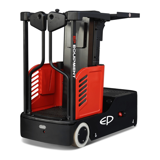
INFORMATION & SPECIFICATIONS 1.2 Introduction Control panel Chassis Storage table Load wheels Lift mast Lift platform Additional storage table Hydraulic pump Drive wheel Flash light Controller Safety Gates Caster Emergency operation area Emergency stop switch Blue light Charger socket Battery Lithium Battery REV. - Page 18 INFORMATION & SPECIFICATIONS Item Control / Display Function Operating information and warning message Display unit display. "Lifting" button Lift the storage table. "Lowering" button Lower the storage table. "Horn" button Activates the horn. "Lifting" button Lift the lift platform. "Lowering" button Lower the lift platform.
- Page 19 INFORMATION & SPECIFICATIONS Item Control / Display Function LED Lamp Display charging status Emergency stop Disconnects the circuit, all electrical functions are switch deactivated. Lower the lift "Lowering" button platform. Cooperate with the under cover,only for service Low control lift and lower button "Lifting"...
-
Page 20: Common Tools
INFORMATION & SPECIFICATIONS This series are electric task support vehicle. Its When the platform is lifted, the door will not important structure is as shown in Figure 50001. open. In the raised position, a pressure- sensitive switch monitors the area between the drive system and the operator platform. -
Page 21: General Tightening Torques
INFORMATION & SPECIFICATIONS 1.4 General Tightening Torques Screws or bolts used on the truck are of 8.8 grade or higher performance level. When you are conducting truck maintenance, you can refer to Table 1.4.1 and Table 1.4.2 to select the suitable screws or bolts for replace- ment. - Page 22 INFORMATION & SPECIFICATIONS Table 1.4.2 Metric Screws/Bolts Tightening Torque Table (n•m) Performance Level 10.9 12.9 Nominal Diameter (mm) Proof Stress (MPa) 10~12 14~17 17~20 16~18 25~30 34~41 41~48 M8×1 17~20 27~32 37~43 43~52 31~36 49~59 68~81 81~96 M10×1 35~41 55~66 76~90 90~106 55~64...
-
Page 23: Maintenance
2. MAINTENANCE... - Page 24 NOTE:...
-
Page 25: Overview
MAINTENANCE 2.1 Overview NOTE Only by performing regular vehicle maintenance Under harsh working conditions: such as, the and repair, can ensure the continuous and external temperature is too high or too low, reliable use of the truck. dusty, or implementing multiple shifts per day, Only specially trained and qualified personnel the maintenance and care interval should be shortened. -
Page 26: Maintenance
MAINTENANCE 2.2 Maintenance Regular inspection and maintenance under harsh conditions of use: 2.2.1 Cleaning Under harsh working conditions, especially: - Dusty environment Do not use flammable liquids to clean the - Corrosive environment truck. - Cold storage environment Before starting to clean, all necessary The maintenance intervals should be shortened security measures must be taken to prevent by half. - Page 27 MAINTENANCE Table 2.1 Inspection & Maintenance List Interval in days/months/years 60 d 90 d Interval in hours 1000 Functions and Control Check the functions of the operation switches and display Check alarm system functions Check foot switch functions Check the emergency stop switch functions Check the cables for damage and if the terminals are secure Check the enable switch of steering wheel functions...
- Page 28 MAINTENANCE Table 2.1 Inspection & Maintenance List (Continued) Interval in days/months/years 60 d 90 d Interval in hours 1000 Power Supply & Drive System Check and lubricate the bearings between drive motor A / L and gearbox Check the drive wheel and load wheel for worn or damage Check the wheel bearings and fixation Check the travel speed...
- Page 29 MAINTENANCE Table 2.1 Inspection & Maintenance List (Continued) Interval in days/months/years 60 d 90 d Interval in hours 1000 Breking System Check the braking functions of electromagnetic brake Check the air gap of electromagnetic brake Check the installation and connection of electromagnetic brake Check the braking distance of electromagnetic brake Lifting System...
- Page 30 MAINTENANCE Table 2.1 Inspection & Maintenance List (Continued) Interval in days/months/years 60 d 90 d Interval in hours 1000 Other Check if the signs are clear and complete Check the chassis for cracks or damages Check the connections of bolts and nuts Checking covering parts for damages Check the casters for wear and cracks Check if the optional features are functioning properly...
-
Page 31: Lubrication
MAINTENANCE 2.2.3 Lubrication Please see Table 2.2 for the lubricants used in this truck. Lubricant CAUTION Improper operations may constitute hazards to the operator's health and life, as well as to The use and disposal of lubricants must be the surrounding environment. carried out in strict accordance with the manufa- cturer's regulations. - Page 32 MAINTENANCE Table 2.2 Lubricants Code Type Specification Amount Position Anti-wear hydraulic oil L-HM46 See the table Hydraulic System Low temperature anti-wear below L-HV32 hydraulic oil (cold storage) Sliding surface Polylub Multi-purpose grease Appropriate amount (See Table 2.4) GA352P Grease (MoS 100 grams Gearbox Table 2.3 Application Amount of...
- Page 33 MAINTENANCE Table 2.4 Sliding Surface Lubrication Table Code Position Steel channel and rollers Steering gear Large chain gear Chains Storage table rollers Caster Load wheels Sliding surface REV. 07/2019...
- Page 34 3. STRUCTURE & FUNCTIONS...
- Page 35 NOTE:...
-
Page 36: Structure & Functions
STRUCTURE & FUNCTIONS 3.1 Structure & Functions 3.1.1 Travel Switch Location: right control assembly; Function: to output travel speed signal to the drive controller; Description: when the vehicle is powered on, the travel switch is at Middle position; Travel Switch Note: Unserviceable. -
Page 37: Storage Table Lowering Switch
STRUCTURE & FUNCTIONS Storage Table Lowering Switch 3.1.5 Storage Table Lowering Switch Location: right control lever; Function: to lower the storage table; Description: the lowering switch is normally- open. When pressing, the switch is on; after re- lease, the switch will automatically reset; Note: Unserviceable. -
Page 38: Tilt Buzzer (Optional)
STRUCTURE & FUNCTIONS 3.1.9 Tilt Buzzer (optional) Location: right side of the hydraulic; Function: when the tilt angle of forklift exceeds the specified value of 4.5 degrees, the buzzer will make sound alarm; Description: 24V operating voltage; Note: Unserviceable. Tilt Buzzer 3.1.10 Tilt Switch (optional) Location: on the chassis bottom plate under rear cover;... -
Page 39: Slack Chain Switch
STRUCTURE & FUNCTIONS 3.1.13 Slack Chain Switch Location: under the front mast cover; Chain Function:Check the chain for looseness; Switch Description: Chain switch is normally closed or opened. When the chain loosens, the switch will be disconnected; Note: Unserviceable. 3.1.14 Lifting Limit Switch Location:Right in front of the mast;... -
Page 40: Dualpmx &Hp Controller (Traction Controller)
STRUCTURE & FUNCTIONS 3.1.17 DUALPMX&HP Controller (Traction Controller) Location: electrical mounting plate; Function: to control the speed of drive motor and pump motor through the signal input by the accelerator; Description: 24V operating voltage, to control the drive motor circuit; &HP DUALPMX Traction Controller... -
Page 41: Pump Motor
STRUCTURE & FUNCTIONS 3.1.21 Pump Motor Location: Under the rear cover; Function: to provide power for gear pump for lifting the loading rack; Pump Motor Description: upon receiving the signal input by control switch, traction controller to control the power transmission of pump motor; Gear Pump Note: Unserviceable. -
Page 42: Accumulator
STRUCTURE & FUNCTIONS 3.1.25 Accumulator Location: Left side of the pump motor; Function: to absorb pressure fluctuations to the hydraulic system from lifting / lowering of platform; Description: working pressure is 3.5 MPa; Note: Unserviceable. Accumulator 3.1.26 Deadman Switch Location: on the pedal cover; Function: when the foot switch is not pressed, you cannot operate the truck;... -
Page 43: Flash Light
STRUCTURE & FUNCTIONS 3.1.28 Flash light Location: Front frame; Function: When the truck is started, the flashing lights keep flashing; Description: 24V operating voltage; Note: Unserviceable. Flash light 3.1.29 Blue light Location: Rear frame; Function: When the truck is started, the Blue lights will show;... -
Page 44: Can Tiller
STRUCTURE & FUNCTIONS 3.1.31 Can Tiller Location: on the rear cover; Function: The function of the Can Tiller board is acquiring analog and digital inputs and sending them to other Can network’s nodes via Can Bus.; Description: 24V operating voltage; Note: Unserviceable. -
Page 45: Chassis System
4. CHASSIS SYSTEM... - Page 46 NOTE:...
-
Page 47: Load Wheel
CHASSIS SYSTEM 4.1 Load Wheel 4.1.1 Removal and Installation Removal Lift the vehicle carefully with lifting equipment (1) through the lifting holes at back; WARNING Make sure the lifting equipment is solid and secure, and the load capacity should be greater than the total weight of the vehicle. -
Page 48: Caster
CHASSIS SYSTEM 4.2 Caster CAUTION 4.2.1 Removal and Installation After long time of use, the drive wheel will wear and tear to certain level, at this time, adjust Removal the height of caster (2) through increasing or decreasing the number of adjustment shims (3) Lift the vehicle carefully with lifting equipment to make the two casters and drive wheel to be through the lifting holes at at front and back;... -
Page 49: Cover
CHASSIS SYSTEM 4.3 Cover 4.3.1 Removal and Installation Removal Press the lift button (2, Figure50107) and low control button (3, Figure50107) to lift mast to proper height; Engage the emergency stop switch and turn off key switch; Unscrew four screws(3), then remove the addtional storage table (2). -
Page 50: Drive System
5. DRIVE SYSTEM... - Page 51 NOTE:...
- Page 52 DRIVE SYSTEM Drive System Name Name Drive Wheel Chain Gear Large Chain gear Steering Motor Chain Speed Encoder Horn Encoder Proximity Switch Electromagnetic brakes Chain gear REV. 07/2019...
-
Page 53: Drive Assembly
DRIVE SYSTEM 5.1 Drive Assembly Unscrew three screws (9), remove the plate (8); 5.1.1 Removal and Installation Remove the steering wheels.(see Section 5.8) Unscrew five screws (7) and then remove the Removal bearings(3) and (2) by order. Remove the drive wheel assy (1) . Lift the vehicle carefully with lifting equipment through the lifting holes at at front and back;... -
Page 54: Electromagnetic Brakes
DRIVE SYSTEM 5.2 Electromagnetic Brakes 5.2.1 Removal and Installation Removal The truck is braked through electromagnetic brake. When the truck is powered off, the The brake is installed on the drive motor. See electromagnetic coil (6) doesn't absorb the Figure 30204 pressure plate (8), the friction force generated between brake pads (2), pressure plate and friction plates (5) will prevent the drive motor... -
Page 55: Faults And Causes
DRIVE SYSTEM After the coil is powered off, the CAUTION Fault pressure plate won't release When installing the brake gear (7), make sure Cause Foreign body blocking the flat key is installed on the shaft of drive motor (8). Fault Abnormal noise after absorption a. -
Page 56: Control Circuit Troubleshooting
DRIVE SYSTEM Air Gap Checks Check if there is foreign body in the air gap that may affect the absorption or bouncing off of the Switch off the truck power connections and pressure plates. pull out the brake connectors; Check the air gap between electromagnetic Spring Checks coil and pressure plate with feeler gauge: measurement method is as shown in Figure... -
Page 57: Drive Wheel
DRIVE SYSTEM 5.3 Drive Wheel - Loosen the six screws (9) with a wrench, and dismantle the large ring gear (10), bearing (11) 5.3.1 Removal and Installation and drive wheel (12) by order. Removal Installation Remove the brake (see Section 5.2.1); - Install according to the reverse order of rem- (See Figure30208) oval. -
Page 58: Drive Motor
DRIVE SYSTEM 5.4 Drive Motor - After replacing carbon brush, running opera- tion must be carried out to the carbon brush: This truck obtains drive force through DC motor. By running the motor with repeated lifting, letting the carbon brush to be fully running, making its surface smooth to fit the rotor. -
Page 59: Checking And Testing
DRIVE SYSTEM Fault Motor smoking or burning smell Testing Stator winding short circuit, motor - Remove the cables on the drive motor; Cause burnt - Carry out ON/OFF test to motor positive and Fault Excessive temperature rise negative electrodes with a multimeter: If connected, the motor is normal;... -
Page 60: Faults And Causes
DRIVE SYSTEM 5.5.2 Faults and Causes Fault Motor does not rotate Cause Speed encoder or its circuit failure On load, motor speed is turning Fault slow Cause Speed encoder or its circuit failure 5.5.3 Checking and Testing Checking - Check if the speed encoder and the appear- ance of cables are in good condition, and if the plug connection is secure;... -
Page 61: Gearbox
DRIVE SYSTEM 5.7 Proximity Switch 5.6 Gearbox 5.7.1 Removal and Installation 5.6.1 Removal and Installation See Section 5.3.1 . Removal Proximity switch is installed on the drive mount- CAUTION ing base. Please add gear oil to the grease nipple on the Pull out the AMP connector on proximity swit- gearbox cover (see Section 2.2.3 for specifica- tion and filling amount) -
Page 62: Faults And Causes
DRIVE SYSTEM 5.7.3 Checking and Testing Adjust the height of Proximity Switch (3,Figure 50220) to make the spacing between proxi- mity switch end face and upper surface of big ring gear to be between 1~2 mm; Turn the key switch on and pull the emergen- cy stop switch, the system will carry out self- test (positioning) to the position of drive wheel;... -
Page 63: Control Circuit Troubleshooting
DRIVE SYSTEM - Check if the inductive distance is normal, if exceeding inductive range, please re-adjust (see 5.5.2). Testing Start the vehicle; Align the inductive surface of proximity switch (2, Figure 50221) to concave of big ring gear, so that it does not sense. Measure if there is 24V voltage between Pin (18#) and Pin (3#) with multimeter. -
Page 64: Steering Motor And Chain
DRIVE SYSTEM 5.8 Steering Motor and chain 5.8.2 Faults and Causes This truck drive small gear to large gear by DC Fault Motor does not rotate steering motor, thus achieving the function of steering. a. Negative electrode cable broken; b. Motor positive and negative electrode with loose terminals;... -
Page 65: Checking And Testing
DRIVE SYSTEM 5.8.3 Checking and Testing Motor with abnormal noise or Fault vibration Checking a. Uneven clearance between - Check if the motor and appearance of stator and rotor; cables are in good condition, and if the plug Cause b. Bearing failures; connection is secure;... -
Page 66: Speed Encoder
DRIVE SYSTEM 5.9 Speed Encoder 5.9.3 Checking and Testing Speed encoder is used to detect the speed Checking of the motor and covert the speed into fixed - Check if the speed encoder and the appear- signals. ance of cables are in good condition, and if the plug connection is secure;... -
Page 67: Control Circuit Troubleshooting
DRIVE SYSTEM 5.9.4 Control Circuit Troubleshooting Control Circuit (Figure 50226) Check if the circuit is broken by using a multi- meter: Set the multimeter to ON-OFF; Check if #90/#93/#94/#95 circuit (circuit between speed encoder and controller) is conducted. REV. 07/2019... -
Page 68: Operating System
6. OPERATING SYSTEM... - Page 69 NOTE:...
-
Page 70: Left Control Assembly
OPERATING SYSTEM 6.1 Left Control Assembly 6.2 Right Control Assembly Removal Removal Left control assembly (5, Figure 50301) is Right control assembly (5,Figure 50302) is mounted on left loading frame. mounted on right loading frame. Unscrew the screw(2) and remove the Unscrew the screws (6), remove the bottom steering wheel (3);... -
Page 71: Button Switch
OPERATING SYSTEM 6.3 Button Switches Testing There are two ways to test it: Push button switches are the switch that make Press the lowering button,if the sixteenth grid the dynamic and static contacts ON or OFF to is not bright,then it indicates the lowering achieve the switching of circuits through push- button or its circuit failure.(see Section 6.9.3) button drive mechanism. -
Page 72: Control Circuit Troubleshooting
OPERATING SYSTEM 6.3.4 Control Circuit Troubleshooting Platform Lifting Button Control Circuit (Figure 50303) Check if the circuit is broken by using a multi- meter: Set the multimeter to ON-OFF; Check if #21 circuit (circuit between lifting button and controller) is conducted; Check if #61 circuit (circuit between lifting button and controller) is conducted;... - Page 73 OPERATING SYSTEM Storage Table Lifting Button Control Circuit (Figure 50306) Check if the circuit is broken by using a multi- meter: Set the multimeter to ON-OFF; Check if #21/#65 circuit (circuit between lower-ing button and controller) is conducted. Storage Table Lowering Button Control Circuit (Figure 50307) Check if the circuit is broken by using a multi-...
- Page 74 OPERATING SYSTEM Horn Button Control Circuit (Figure 50305) Check if the circuit is broken by using a multi- meter: Set the multimeter to ON-OFF; Check if #21/#14 circuit (circuit between lower-ing button and controller) is conducted. Horn Checks Energize the horn with a voltage of 24V: Horn sounds, the horn is working properly;...
-
Page 75: Travel Switch
OPERATING SYSTEM 6.4 Travel Switch 6.4.3 Checking and Testing Travel switch provides forward or backward in- Checking put signals for the vehicle. - Check if the appearance of travel switch and its wiring harness are in good condition, and if the connectors are connected securely. 6.4.1 Removal and Installation Testing See Section 6.2 . -
Page 76: Proximity Switch
OPERATING SYSTEM 6.5 Enable Switch Testing Start the vehicle; 6.5.1 Removal and Installation Measure if there is 24V voltage between Pin (18#) and Pin (3#) with multimeter. If there is See Section 6.1and 6.2 . no voltage, check if the circuit is connected; if Installation there is voltage, move on to the next step. - Page 77 OPERATING SYSTEM Control Circuit Troubleshooting Proximity Switch Control Circuit (Right hand) (Figure 50309) Check if the circuit is broken by using a multi- meter: Set the multimeter to ON-OFF; Check if #3/#107/#18 circuit (circuit between proximity switch and controller) is conducted. REV.
-
Page 78: Stepper Motor
OPERATING SYSTEM 6.6 Stepper Motor Stepper motor provides the vehicle with steering input signals. 6.6.1 Removal and Installation See Section 6.2 . 6.6.2 Faults and Causes Operate the steering wheel, the “STEPPER MOTOR”, turn the steering wheel, vehicle does not respond to the if the voltage display is always "0", it indicates steering signal;... -
Page 79: Key Switch
OPERATING SYSTEM 6.7 Key Switch 6.7.3 Checking and Testing Key switch is used to START / STOP the truck. Checking - Check if the appearance of key switch its wiring harness are in good condition, and if 6.7.1 Removal and Installation the connectors are connected securely. -
Page 80: Emergency Stop Switch
OPERATING SYSTEM 6.8 Emergency Stop Switch Testing Emergency switch is used for emergency cut-off Check if the emergency switch circuit is con- of the power supply to all the control circuits. ducted; 6.8.1 Removal and Installation Carry out ON/OFF test to emergency switch with a multimeter: See Section 6.2 . -
Page 81: Charge Gauge
OPERATING SYSTEM 6.9 Charge Gauge 6.9.3 Checking and Testing Charge gauge is used to display remaining Checking battery power of forklift, working hours (this - Check if the appearance of charge gauge its function is available on the component with wiring harness are in good condition, and if timer function). -
Page 82: Control Circuit Troubleshooting
OPERATING SYSTEM right hand enable switch aux lift switch aux lower switch horn main lift switch forward switch main lower switch Reverse switch 6.9.4 Control Circuit Troubleshooting Charge Gauge Control Circuit (See Electrical Schematic Diagrams ) Check if the circuit is broken by using a multi- meter: Set the multimeter to ON-OFF;... -
Page 83: Hydraulic System
7. HYDRAULIC SYSTEM... - Page 84 NOTE:...
-
Page 85: Overview
HYDRAULIC SYSTEM Hydraulic Oil The system pressure of the entire hydraulic system pressure is provided by hydraulic power Hydraulic oil for truck: unit system, which is used for lifting. While the Specifications: Anti-wear Hydraulic Oil L-HM46. hydraulic power unit is equipped with a relief valve to ensure that the entire system pressure * For cold storage: Low Temperature Anti-wear is always within the safety limits that can lift the... -
Page 86: Hydraulic Schematic Diagram
HYDRAULIC SYSTEM 7.1.1 Hydraulic Schematic Diagram REV. 07/2019... -
Page 87: Pump And Motor Assembly
HYDRAULIC SYSTEM 7.2 Pump and Motor Assembly 7.2.2 Component 7.2.1 Removal and Installation Removal Press the lift button (2, Figure50107) and low control button (3, Figure50107) to lift mast to proper height; Engage the emergency stop switch and turn off key switch; Remove the rear cover(see section 4.3.1);... -
Page 88: Pump Motor
HYDRAULIC SYSTEM 7.3 Pump Motor Adjustment After replacing the motor or carbon brush, 7.3.1 Removal and Installation conduction test must be carried out to the Removal motor (see Section 7.3.3). After replacing carbon brush, running opera- tion must be carried out to the carbon brush: By running the motor with repeated lifting, letting the carbon brush to be fully running, making its surface smooth to fit the rotor. -
Page 89: Checking And Testing
HYDRAULIC SYSTEM 7.3.3 Checking and Testing Motor with abnormal noise or Fault vibration Checking a. Uneven clearance between - Check if the pump motor and appearance of stator and rotor; cables are in good condition, and if the plug Cause b. -
Page 90: Aux Pump Motor
HYDRAULIC SYSTEM 7.4 AUX Pump Motor 7.4.2 Faults and Causes 7.4.1 Removal and Installation Fault Motor does not rotate Removal a. electrode cable broken; Press the lift button (2, Figure50107) and low b. Armature winding with broken control button (3, Figure50107) to lift mast to circuits;... -
Page 91: Checking And Testing
HYDRAULIC SYSTEM 7.4.3 Checking and Testing Checking - Check if the pump motor and appearance of cables are in good condition, and if the plug connection is secure; - Check if the circuit is connected. Testing Check if aux motor pump circuit is conducted; Energize the aux motor pump with a voltage of 24V: Press the lift button and lower button, if the... -
Page 92: Solenoid Valve
HYDRAULIC SYSTEM 7.5 Solenoid Valve Fault Internal leakage When solenoid valve coil is energized (there Damaged seals or spring Cause is voltage between coil end A and B), the deformations electromagnetic coil generates electromagnetic Fault External leakage force, and the spool will move, the valve will open, and the vehicle will be lowered. -
Page 93: Control Circuit Troubleshooting
HYDRAULIC SYSTEM - Remove the solenoid valve, take out the spool and spool sleeve, clean with CCI4 to enhance the flexibility of the moving of spool within the spool sleeve. During disassembly, pay attention to the sequence of assembly and position of external wiring for correct re- assembly and wiring, also check the oil mist spray orifice for blockage and if the lubricant is sufficient. -
Page 94: Reach Cylinder
HYDRAULIC SYSTEM 7.6 Cylinder Upon removal, the damage to cylinder threads, oil port threads, cylinder cap threads, 7.6.1 Cylinder Removal Precautions piston rod surface and inner cylinder wall should be prevented. Before removing the cylinder, be sure to reli- In order to prevent piston rod from bending or eve the hydraulic circuit first, which is to lower deformation, support it wooden block when the lifting mast to the bottom. -
Page 95: Cylinder Installation Precautions
HYDRAULIC SYSTEM CAUTION Cylinder Cap O-ring is quite flexible and easy to install, but it must not be pulled up to the extent of permanent deformation, nor scroll it while installing; Y-ring or X-ring needs to be identified if it is Cylinder Wrenches for shaft or hole to avoid misplacement;... -
Page 96: Accumulator
HYDRAULIC SYSTEM 7.7 Accumulator CAUTION The truck adopts diaphragm-type accumulator. As the accumulator retains some hydraulic It consists of oil and gas section with a gas se- oil, therefore, before removal, please place a als, among which, the oil of accumulator is container or oil cloth underneath it. -
Page 97: Hydraulic Troubleshooting
HYDRAULIC SYSTEM 7.8 Hydraulic Troubleshooting Fault Symptom Failure Causes Troubleshooting Measures a. Insufficient oil; 1. Check the hydraulic oil level. b. High viscosity of oil; 2. Replace the hydraulic oil. c. Oil suction pipe air leak; 3. Check the oil suction pipe. Noisy pump d. -
Page 98: Hydraulic Symbol
HYDRAULIC SYSTEM 7.9 Hydraulic Symbol Symbol Description Symbol Description Tank Pipe end below liquid Explosion-proof valve level Tank Pipe end above liquid Check valve level Cylinder Filter Single-acting direction Service line (Supply line or return Relief valve line) Control line Throttle valve (Drain line) With pressure... -
Page 99: Electrical System
8. ELECTRICAL SYSTEM... - Page 100 NOTE:...
-
Page 101: Controller
ELECTRICAL SYSTEM Main 8.1 Controller Fuse 1 Contactor Relay Controller Functions Electrical control of this truck is mainly driven by traction controller and steering controller. Controller: traction controller: mainly used for the control of drive motor Traction Steering controller: mainly used for the control Controller of steering motor - Other:... -
Page 102: Removal And Installation
ELECTRICAL SYSTEM 8.1.1 Removal and Installation Removal Remove the cover; Remove the wiring harness, cables and copp- er strips on the controller; Unscrew the four screws (4) with a wrench and remove the traction controller (3); - Unscrew the four screws (2) with a wrench and remove the steering controller (1). -
Page 103: Controller Interface Function
ELECTRICAL SYSTEM 8.1.2 Controller Interface Function &HP Traction Controller (DUALPMX A Interface Pin No. Signal Name Description Input of the switch DI0. The input is activated when it is connected to +Batt. With the logic hardware properly configured it can be used to supply the EB and MC positive. - Page 104 ELECTRICAL SYSTEM A Interface Pin No. Signal Name Description Input of the switch DI2. The input is activated when the external switch is opened. The default function is the controller “CUTBACK” input, opening the switch truck speed is reduced. Input of the switch DI6. The input is activated when it is connected to +Batt.
- Page 105 ELECTRICAL SYSTEM A Interface Pin No. Signal Name Description Inching (Backing) function, backward direction input. It A#16 DI10 must be connected to the inching backward switch. Inching (Backing) function, forward direction input. It A#17 DI8 must be connected to the inching forward switch. Input of the switch DI11.
- Page 106 ELECTRICAL SYSTEM A Interface Pin No. Signal Name Description Negative of the protected horn electrovalve driver (driving A#26 HORN to –Batt). A#27 CAN L Low level CAN-BUS voltage I/O A#28 CAN H High level CAN-BUS voltage I/O. Input of the switch DI9. The input is activated when the external switch is opened.
- Page 107 ELECTRICAL SYSTEM Steering Controller (EPS-DC0) A Interface Pin No. Signal Name Description DRIVE SWITCH Traction Travel Demand Input. 2nd Toggle Switch or CCW (Left) Limit Switch (LLS). 1st Toggle Switch or CW (Right) Limit Switch (RLS). Safety Switch Lower Voltage Point. Safety Switch Higher Voltage Point.
- Page 108 ELECTRICAL SYSTEM B Interface Pin No. Signal Name Description NPOT FB POT Negative Supply. PPOT FB POT Positive Supply. THMOT Motor Thermal Sensor (KTY84-130) Input. +5VDC Encoder Positive Supply. PPOC Twin SP POT Positive Supply (5 Vdc). CPOT FB POT Wiper. Encoder Channel B.
- Page 109 ELECTRICAL SYSTEM CAN-TILLER-ING A Interface Pin No. Signal Name Description First digital input. Second digital input. Third digital input. Fourth digital input. Fifth digital input. Sixth digital input. Seventh digital input. Eighth digital input. PPOT Positive of AI1, AI2, AI3, AI4, AI5, AI6. A#10 Second analog input.
- Page 110 ELECTRICAL SYSTEM B Interface Pin No. Signal Name Description CAN LOW Low level CAN-BUS voltage I/O. -BATT -Batt. +KEY Key input. CAN HIGH High level CAN-BUS voltage I/O. +BATT +Batt, short circuit to CNA#14. Internal connected to DI1 with a 100 Ω resistance. C Interface Pin No.
-
Page 111: Fuse 2
ELECTRICAL SYSTEM 8.2 Fuse The entire vehicle is installed with three fuses altogether. When there is fuse failure, the truck may not be able to run properly due to that. Status Function Fuse 1 Fuse 2 Fuse 3 Fuse 1 350A ×... -
Page 112: Checking And Testing
ELECTRICAL SYSTEM 8.2.2 Checking and Testing Checking - Check the fuses for damage, check the connectors at terminal lugs for loosening or poor connection of leads. Testing Turn the key switch to "OFF", remove key; pull out the battery plug and disconnect the power supply. -
Page 113: Main Contactor
ELECTRICAL SYSTEM 8.3 Main Contactor This truck is using dual contactors with norm- ally-opened contacts. And the ON/OFF of the contactors is controlled through controller, thus to achieve the control of ON/OFF of the vehicle. When the contactor coil is energized, the coil current will create a magnetic field, making the After the replacement, re-install in reverse static stator core produce a steady magnetic... -
Page 114: Checking And Testing
ELECTRICAL SYSTEM 8.3.3 Checking and Testing Visual Inspection Check the surface and appearance of contac- tor; Visually check the surface of contactor for scratches, damages and stains; If any of the above case is found, please replace with new contactor. Coil Checks Disconnect the cables on the contactor;... -
Page 115: Limit Switch
ELECTRICAL SYSTEM 8.4 Iimit Switch Remove the left control lever and right control lever( see Section 6.1) Limit switch is variable roller lever type. By Disconnect the connection between door safety function: switch and connecting harness(22); - Slack Chain Switch - Lifting Limit Switch Unscrew the nut (25) and screw(23), and - Speed Reduction Switch... -
Page 116: Faults And Causes
ELECTRICAL SYSTEM Switch Slack Chain Lifting Limit Switch Normally-closed (NC): Fault Lifting mechanism cannot lift Terminal (1) and Terminal (3) for connection of a. Lifting limit switch is disconnect- wiring harness connector to switch base Cause b. Lifting limit switch with broken Normally-closed (NO): circuit. -
Page 117: Checking And Testing
ELECTRICAL SYSTEM 8.4.3 Checking and Testing Checking Check if the appearance of these switches and its wiring harness are in good condition, and if the connectors are connected securely; Repeatedly press the these switches to che- ck if it can reset properly. Testing Enter TESTER Menu to check the status of the switch;... - Page 118 ELECTRICAL SYSTEM Control Circuit Slack Chain Switch (Figure 50517) Check if the circuit is broken by using a multi- meter: Set the multimeter to ON-OFF; Check if #3/#84/#85 circuit (circuit between Slack chain switch and controller) is conducted. emergency key switch stop switch Lifting Limit Switch and speed reduction Switch Control Circuit (Figure 50518)
- Page 119 ELECTRICAL SYSTEM Door Safety Switch Control Circuit (Figure 50519) Check if the circuit is broken by using a multi- meter: Set the multimeter to ON-OFF; Check if #3/#126/#108 circuit (circuit between switches and controller) is conducted. emergency key switch stop switch REV.
-
Page 120: Deadman Switch
ELECTRICAL SYSTEM 8.5 Deadman Switch 8.5.1 Removal and Installation Removal See Section 3.1 for mounting position of foot switch. -Press the lift button (2, Figure50107) and low control button (3, Figure50107) to lift mast to proper height; - Engage the emergency stop switch and turn off key switch;... -
Page 121: Checking And Testing
ELECTRICAL SYSTEM 8.5.3 Checking and Testing Checking Check if the appearance of foot switch and its wiring harness are in good condition, and if the connectors are connected securely; Repeatedly press the foot switch to check if it can reset properly. Testing Enter TESTER Menu to check the status of the switch: “HANDLE/SEAT SW.”, press the... -
Page 122: Tilt Switch
ELECTRICAL SYSTEM 8.6 Tilt Switch(Optional) 8.6.2 Faults and Causes This forklift is equipped with a level sensor, Under lifting state, travel on the namely, tilt switch. When the tilt angle exceeds Fault ramp greater than 4.5 degrees, no 4.5 degrees, the cabin will be lifted, and the tilt alarm sound is heard buzzer will emit continuous alarm. -
Page 123: Blue Light
ELECTRICAL SYSTEM 8.7 Blue Light 8.7.2 Faults and Causes This truck has two lights mounted the frame. When the vehicle starts, the warn- Fault When the vehicle starts, the blue lights will be lit ing light won't light up up, the flash light will be flash. a. -
Page 124: Flash Light
ELECTRICAL SYSTEM 8.8 Flash Light 8.8.2 Faults and Causes When the vehicle starts, the flash 8.8.1 Removal and Installation Fault light won't flash Removal a. Flash light failure; Cause b. Flash light circuit not condu- Remove the addtional storage table(see cted. -
Page 125: Pressure-Sensitive Switch
ELECTRICAL SYSTEM 8.9 Pressure-sensitive switch 8.9.2 Faults and Causes In the raised position, a pressure -sensitive In the lifting state, there are switch monitors the area between the drive Fault objects under the vehicle that can system and the operator platform. If the area is be lowered occupied(e.g by an objectorperson) lowering is stopped. -
Page 126: Button Switch
ELECTRICAL SYSTEM 8.10 Button Switch 8.10.2 Faults and Causes Push button switch are the switch that makes Button enable switch control the dynamic and static contacts ON or OFF to achieve the switching of circuits through push- Operate the push button switch, button drive mechanism. -
Page 127: Checking And Testing
ELECTRICAL SYSTEM 8.10.3 Checking and Testing Check if the push button switch circuit is connected; Checking Carry out ON/OFF test to the push button - Check if the push button switch and the switch with a multimeter: appearance of cables are in good condition, push button switch at original position, broken and if the plug connection is secure. - Page 128 ELECTRICAL SYSTEM Platform Lifting Button Control Circuit (Figure 50530) Check if the circuit is broken by using a multi- meter: Set the multimeter to ON-OFF; Check if #115 circuit (circuit between lifting button and controller) is conducted; Check if #124/#18 circuit (circuit between lifting button and GND) is conducted;...
-
Page 129: Led Charging Indicator
ELECTRICAL SYSTEM 8.11 LED Charging Indicator 8.11.2 Faults and Causes LED charging indicator is used to display Fault No display from indicator charge status, which can display in three colors: a. Indicator failure; red, yellow and green. Cause b. Indicator circuit not connected; c. - Page 130 ELECTRICAL SYSTEM operational REV. 07/2019...
-
Page 131: Tester Menu
ELECTRICAL SYSTEM 8.12 TESTER Menu The parameters in TESTER Menu are real- time presentation of the running status of the equipment. Traction Controller (DUALPMX&HP) Parameters Description Remark Key voltage value measured in real time KEY VOLTAGE Display the current voltage ( V ) (pin A10). - Page 132 ELECTRICAL SYSTEM Parameters Description Remark TAI4 POT NONE Display the current voltage Display the current voltage ( TAI3 POT NONE Display the current voltage ( TAI2 LIFT LOW POT NONE Display the current voltage ( TAI1 POT NONE Display the current voltage ( CPOT3 POT NONE Display the current voltage (...
- Page 133 ELECTRICAL SYSTEM Parameters Description Remark It is the status of safety switch on tiller TDI1 SAFETY SW ON +VB controller DI14 SW NONE OFF GND DI13 SW NONE OFF +VB DI12 ADD LOW SW It is the status of addtional lower switch OFF +VB DI13 ADD LIFT SW It is the status of addtional lift switch...
- Page 134 ELECTRICAL SYSTEM Parameters Description Remark Display the current angle ( ° STEER ANGLE Current steered wheel angle ENCODERCNT LEFT NONE ENCODERCNT NONE RIGHT ENCODER LEFT NONE This is the speed of the traction motor ENCODER Right measured with the encoder FREQUENCY LEFT NONE This is the traction frequency of the sine...
- Page 135 ELECTRICAL SYSTEM Steering Controller (EPS-DC0) Parameters Description Remark STEPPER MOTOR Check the voltage of stepper motor Display the current voltage ( V ) READ FBPT AT SW1 SET POINT POT. TRUCK SPEED SLOPE PEAK TRUCK MOVING SM ALARM SWITCH MM ALARM SWITCH ACW LIMIT LEVEL CW LIMIT LEVEL ENDSTROKE ACW...
- Page 136 ELECTRICAL SYSTEM 8.13- Handheld Unit (Optional) 8.14.2 Handheld Unit Menu Options Handheld unit must be used together with con- Start troller, if necessary, it can be purchased from 启 动 our company or dealer. * CONS AFG ZP100 * RS232 CONSOLE CAN CONSOLE AUTOSCAN CAN Display...
- Page 137 ELECTRICAL SYSTEM Previous Page * MAIN MENU * PARAMETER CHANGE TESTER ALAARMS PROGRAM VACC SAVE PARAMETERS RESTORE PARAMETERS SET MODEL With Navigator keys (Figure 80513), you can carry out menu switching; “OK”, select ENTER the menu. PARAMETER CHANGE : parameter change TESTER : vehicle running test ALARMS...
-
Page 138: A Handheld Unit (Optional)
ELECTRICAL SYSTEM 8.13-B Handheld Unit (Optional) • The number of times that each alarm occurs con- secutively. A Zapi Handset is available that is designed specifi- • The Hour Meter reading (value) when the latest cally for use with the Zapi controller. It serves multiple event of every alarm occurred. -
Page 139: Settings And Adjustments
ELECTRICAL SYSTEM 8.13.3 Settings and Adjustments 8.13.3.1. Set Options To set options proceed as follows and refer to Table 4- 1. Connect the Zapi Handset, refer to paragraph 8.13.1.1. 2. Press the ROLL up button (1, Figure 90535) and the SET up button (5) at the same time to enter the CONFIG MENU. -
Page 140: Parameter Change
ELECTRICAL SYSTEM 8.13.5 Parameter Change To change a parameter proceed as follows and refer to Table 4-4: 1. Connect the Zapi Handset, refer to paragraph 8.13.1.1. 2 . Press the ENTER button (3) t o f i n d PA R A M E T E RCHANGE display. -
Page 141: Traction Controller
ELECTRICAL SYSTEM 8.14 Controller Error Message code (see Chapter 9 - Troubleshooting); while the when the components failures which may Electrical faults are mainly caused by electrical affect the ON/OFF of control circuit occur to components failure or electrical circuit failure. the electrical circuit, the controller will alarm for Wherein, when some components failures error, and fault information will be displayed on... - Page 142 ELECTRICAL SYSTEM Error Message Possible cause Fault elimination Error text Error "A) If the problem occurs at start up (the LC does not close at all), check: - Motor internal connections; - Motor power cables connections; - If the motor connection are OK, the problem is inside the controller.
-
Page 143: Controller Error Message
ELECTRICAL SYSTEM Error Message Possible cause Fault elimination Error text Error "A If the problem occurs at start-up (the LC does not "Before switching the LC on, the close), check: software checks the power bridge: - motor internal connections it turns on alternatively the low-side (ohmic continuity);... - Page 144 ELECTRICAL SYSTEM Error Message Possible cause Fault elimination Error text Error "1-Check if an external load in parallel to the capacitor bank, which sinks current from the capacitors-charging circuit, thus preventing the caps When the key is switched on, from charging well. Check if a the inverter tries to charge lamp or a dc/dc converter or the power capacitors through...
- Page 145 ELECTRICAL SYSTEM Error Message Possible cause Fault elimination Error text Error "It is necessary to improve the controller cooling. To realize an adequate cooling in case of finned heat sink important factors are the air flux and cooling-air temperature. If the The temperature of the controller thermal dissipation is realized by base plate is above 85 °C.
- Page 146 ELECTRICAL SYSTEM Error Message Possible cause Fault elimination Error text Error CURRENT SENS. KO "1- Check if there is a short or a low impedance pull-down between NMC The driver of the LC coil is (A12) and -B. DRIVER SHORTED shorted.
- Page 147 ELECTRICAL SYSTEM Error Message Possible cause Fault elimination Error text Error "1- Check wirings. 2- Check microswitches for "Incorrect starting sequence. failures. Possible reasons for this alarm are: 3- Through the TESTER 1- A travel demand active at key- INCORRECT START function, check the states of the inputs are coherent with 2- Man-presence sensor active at...
- Page 148 ELECTRICAL SYSTEM Error Message Possible cause Fault elimination Error text Error "1-check the battery charge if the battery charge level is to level EP BMS MC OPEN low,the BMS require the main 2-check if the battery is ok contactor open,this alarm occurs 3-replace the BMS"...
- Page 149 ELECTRICAL SYSTEM Error Message Possible cause Fault elimination Error text Error "1- Check the electrical and the mechanical functionality of the encoder and the wires crimping. 2- Check the mechanical installation of the encoder, if This fault occurs when the the encoder slips frequency supplied to the motor is inside its housing it will raise...
- Page 150 ELECTRICAL SYSTEM Error Message Possible cause Fault elimination Error text Error "If the alarm condition occurs again, ask for assistance to a EP The motor current has overcome technician. OVERLOAD the limit fixed by hardware. The fault condition could be affected by wrong adjustments of motor parameters."...
- Page 151 ELECTRICAL SYSTEM Error Message Possible cause Fault elimination Error text Error "1-It is suggested to repeat the acquiring procedure of MIN LIFT and PUMP VACC The minimum voltage of the lift MAX LIFT NOT OK potentiometer is not correctly set. 2-check the wiring of the lift pot 3-check if it's the lift pot fault"...
- Page 152 ELECTRICAL SYSTEM Error Message Possible cause Fault elimination Error text Error "For the versions where the smart driver is not installed (36/48V and 80V), it is possible to decide where the positive supply for pin A2 comes from by choosing a dedicated hardware configuration.
- Page 153 ELECTRICAL SYSTEM Error Message Possible cause Fault elimination Error text Error Wrong software version on supervisor Upload the correct software WRONG SLAVE VER. version At start-up there is a mismatch in the parameter checksum between Restore and save again the M/S PAR CHK MISM the master and the supervisor parameters list.
- Page 154 ELECTRICAL SYSTEM Error Message Possible cause Fault elimination Error text Error "This fault is displayed when the controller detects an overvoltage condition. Overvoltage threshold depends on the nominal voltage of the controller. Nominal voltage 24V 36/48V 72/80V 96V Overvoltage threshold 35V 65V 115V 130V "If the alarm happens during As soon as the fault occurs,...
- Page 155 ELECTRICAL SYSTEM Error Message Possible cause Fault elimination Error text Error This type of fault is related to the connection of the EEPROM EEPROM KO internal components. Replace is not ok the logic board. The controller has restored the "1- A travel demand or a pump default settings.
- Page 156 ELECTRICAL SYSTEM Error Message Possible cause Fault elimination Error text Error "1- Check the EVP condition. No load is connected between 2- Check the EVP wiring. EVP COIL OPEN the EVP output (A24) and the 3- If the problem is not electrovalve positive terminal.
- Page 157 ELECTRICAL SYSTEM Error Message Possible cause Fault elimination Error text Error "1- Check if the resistance of the sensor is what expected measuring The output of the motor thermal its resistance. SENS MOT TEMP KO sensor is out of range. 2- Check the wiring.
- Page 158 ELECTRICAL SYSTEM Error Message Possible cause Fault elimination Error text Error "The controller receives from the CAN bus the message that another controller in the net is in fault condition; as a consequence the Check if any other device on the WAITING FOR NODE controller itself cannot enter into an CAN bus is in fault condition.
- Page 159 ELECTRICAL SYSTEM 8.14.2 Steering Controller (EPS-ACO) Error Message Possible cause Fault elimination Error text Error M a i n u C a n d S l a v e u C communicate via a local serial interface. This alarm occurs when It is necessary to replace SERIAL ERR #1 the slave uC does not receive the...
- Page 160 ELECTRICAL SYSTEM Error Message Possible cause Fault elimination Error text Error This alarm occurs two ways: 1) In the initial rest state after key on, if the outputs of the current amplifiers are not comprised in the It is necessary to replace STBY I HIGH window 2.2 to 2.8 Vdc.
-
Page 161: Steering Controller (Eps-Aco)
ELECTRICAL SYSTEM Error Message Possible cause Fault elimination Error text Error Check the power fuse is OK. Check the battery positive This alarm occurs when the current arrives to the controller. in the phase W of the motor is zero Check the continuity of POWER FAILURE #1 and the motor is commanded for... - Page 162 ELECTRICAL SYSTEM Error Message Possible cause Fault elimination Error text Error AUTOC.MALFUNC. —— —— This alarm occurs if the frequency and the amplitude of the voltages from the stepper motor lines are mismatched in between In normal It is necessary to replace STEPPER MOTOR MISM condition when the amplitude of the controller.
- Page 163 ELECTRICAL SYSTEM Error Message Possible cause Fault elimination Error text Error This alarm occurs if the feedback potentiometer (CPOT on CNB#6) changes with a jerk larger than 0.3 C h a n g e t h e f e e d b a c k JERKING FB POT V in 16 msec.
- Page 164 ELECTRICAL SYSTEM Error Message Possible cause Fault elimination Error text Error Check the potentiometer connected to CNB#6 is right working. If toggle switches are connected to CNA#2 and CNA#3, verify they are right working and the setting AUX FUNCTION 11 is correct. Verify also This alarm occurs for an error in the sensor bearing in the POSITION ERROR...
- Page 165 ELECTRICAL SYSTEM Error Message Possible cause Fault elimination Error text Error Check the continuity of the This alarm occurs when the mean stepper motor connections. voltage on the Quadrature line In particular the resistance of the stepper motor (connection between CNA#8 and the Q LINE SENSOR KO CNA#8) is not null: the voltage on minus battery (with the...
- Page 166 ELECTRICAL SYSTEM Error Message Possible cause Fault elimination Error text Error This alarm occurs only when the setting CAN BUS is PRESENT. C h e c k t h e C A N B u s Then the eps-ac0 must receive the communication system and CAN BUS KO event messages from the traction...
- Page 167 ELECTRICAL SYSTEM Error Message Possible cause Fault elimination Error text Error This alarm occurs if the connection CNA#5 (K1) is around a voltage of 12 Vdc when switching on the key. This alarm occurs at key on if the In fact, when the safety slave uC detects the safety contact, KM CLOSED contacts are open, K1 is...
-
Page 168: Cable Wiring Diagrams
ELECTRICAL SYSTEM 8.15 Cable Wiring Diagrams Name Name Lithium battery EPS Cable+ B Cable+ EPS Cable- B Cable- Steering Motor Cable V Pump Power Cable + Steering Motor Cable W Pump Power Cable - Controller + EPS Controller Cable E-F Cable REV. -
Page 169: Electrical Schematic Diagrams
ELECTRICAL SYSTEM 8.16 Electrical Schematic Diagrams REV. 07/2019... - Page 170 ELECTRICAL SYSTEM REV. 07/2019...
-
Page 171: Wiring Harness And Connectors
ELECTRICAL SYSTEM 8.17 Wiring Harness and Connectors TO Handheld unit communication cable REV. 07/2019... - Page 172 ELECTRICAL SYSTEM REV. 07/2019...
- Page 173 9. TROUBLESHOOTING...
- Page 174 NOTE:...
-
Page 175: Troubleshooting
TROUBLESHOOTING 9.1 Troubleshooting Solutions of Common Faults Table 9.1 lists the common faults that may occur and handling methods. Mainly consists of the following items: Table 9.1 Troubleshooting of Common Faults Fault Fault Symptom Troubleshooting Order * Troubleshooting Measures Power supply 1. - Page 176 TROUBLESHOOTING Table 9.1 Troubleshooting of Common Faults (continued) Fault Fault Symptom Troubleshooting Order * Troubleshooting Measures Hydraulic 1. The platform cannot 1. Pump motor does not work: 1. Pump motor does not work: Failure lift a. Foot switch and door safety 1) Check if the foot switch and switch or its circuit connection door safety switch or the con-...
- Page 177 TROUBLESHOOTING Table 9.1 Troubleshooting of Common Faults (continued) Fault Fault Symptom Troubleshooting Order * Troubleshooting Measures 3. The paltform cannot a. Solenoid valve or its circuit (see Section 7.6) connection failure 4) Clean or replace the valve; be lowered (see Section 7.8); b.
-
Page 178: Troubleshooting Solutions Of Common Faults
TROUBLESHOOTING Table 9.1 Troubleshooting of Common Faults (continued) Fault Fault Symptom Troubleshooting Order * Troubleshooting Measures Steering Fault 1. The vehicle cannot a. Stepper motor or its circuit Controller failure error, carry out connection failure troubleshooting according to the be steered (the fault code information on the vehicle can travel) b. -
Page 179: Appendix
APPENDIX... - Page 180 NOTE:...
- Page 181 A SERVICE MANUAL - MAST...
- Page 182 NOTE:...
- Page 183 SERVICE MANUAL - MAST A1 Three-stage Mast A1-1.1 Chain Adjustment A1-1.2 Chain 1 Replacement Press the lift button (2, Figure50107) and low control button (3, Figure50107) to lift mast to proper height;(see section 4.3.1) Outer Mast Engage the emergency stop switch and turn off key switch;...
- Page 184 SERVICE MANUAL - MAST A1-1.3 Chain 2 Replacement Press the lift button (2, Figure50107) and low control button (3, Figure50107) to lift mast to proper height;(see section 4.3.1) Engage the emergency stop switch and turn off key switch; Unscrew the twenty fastening screws (3,Figure 50602) and remove the back cover(1,Figure 50602) and side cover(4,...
- Page 185 SERVICE MANUAL - MAST REV. 07/2019...
-
Page 186: A1-1.2 Chain 2 Replacement
SERVICE MANUAL - MAST A1-2.1 Drag Chain Replacement A1-2.2 Drag Chain harness Replacement A1-2.2.1 Left Drag Chain harness A1-2.1.1 Left Drag Chain Replacement Replacement -Press the lift button (2, Figure50107) and low -Press the lift button (2, Figure50107) and low control button (3, Figure50107) to lift mast to control button (3, Figure50107) to lift mast to proper height;(see section 4.3.1) - Page 187 SERVICE MANUAL - MAST REV. 07/2019...
-
Page 188: A1-3 Cylinder
SERVICE MANUAL - MAST A1-3 Cylinder A1-3.1 Cylinder Removal - Press the lift button (2, Figure50107) and low control button (3, Figure50107) to lift mast to proper height;(see section 4.3.1) -Engage the emergency stop switch; - Remove the upper cover (6) (see Section 4.3.1);... -
Page 189: A1-3.2 Cylinder Maintenance
SERVICE MANUAL - MAST A1-3.2 Cylinder Maintenance CAUTION Use suitable hose clamps to avoid cylinder deformation caused by severely tight hose clamp. Carry out the maintenance work in a clean environment to prevent impurities from entering into cylinder, causing cylinder damage. -
Page 190: B Service Manual - Battery
B SERVICE MANUAL - BATTERY... - Page 191 NOTE:...
-
Page 192: B1 Lead-Acid Battery
SERVICE MANUAL - BATTERY B1 Lead-acid Battery As for failure to comply with instructions for use, maintenance without using original parts, user B1-1 Safety and Warnings corruption, or viola-tion of provisions when adding electrolyte and other circumstances, the quality When operating on battery, you must wear assurance will automatically void. -
Page 193: B1-2.3 Charging
SERVICE MANUAL - BATTERY B1-2.3 Charging B1-3 Maintenance & Care B1-3.1 Daily Maintenance When charging, only DC can be used. Connect the battery with proper charger for Charge the discharged battery; specification and size to avoid overload of circuit and interface, and to avoid electrolyte Visual inspection for excessive dirtiness and foaming or overflow from the cell;... -
Page 194: B1-3.3 Monthly Maintenance
SERVICE MANUAL - BATTERY - As for a group of normal batteries, when the WARNING battery is discharged for 80% (the instrument alarms and prompts low battery, you should Add only distilled water. recharge in a timely manner), the open circuit Before adding distilled water, check if the voltage should be around 1.93V, specific buoy can move up and down properly to... -
Page 195: B1-4 Storage
SERVICE MANUAL - BATTERY B1-4 Storage 3. Make sure that the "+" and "-" output termin- als are not sulfated (with white salt). When the battery is not used for a long time, Slight sulfation: clean top of the element with the battery should be filled up and stored in a a damp cloth. - Page 196 SERVICE MANUAL - BATTERY Battery Fault Analysis Fault Negative Phenomena Cause Handling Methods Electrode 1. Battery capacity drops 1. Insufficient initial charge 1. Over-discharge method during normal discharge 2. Long time of storage under 2. Repeated charging plate sulfation 2. Density drops to be lower the state of discharge method than normal value...
- Page 197 SERVICE MANUAL - BATTERY Battery Fault Analysis Fault Negative Phenomena Cause Handling Methods Battery Short 1. Low static voltage below 2V 1. Electrode plate deformed and Battery needs to be replaced 2. Electrolyte density is too low short circuit Circuit 3.
-
Page 198: B2 Maintenance-Free Battery
SERVICE MANUAL - BATTERY B2 Maintenance-free Battery B2-2 Use of Battery B2-2.1 Pre-use Checks B2-1 Safety and Warnings Check if the fixing bolts on the bracket for the The battery should be away from heat source battery are tightened, insecure installation and the place that is easy to produce sparks, may cause damage to the case due to the the safety distance should be greater than... -
Page 199: B2-2.3 Charging
SERVICE MANUAL - BATTERY B2-2.3 Charging B2-3 Maintenance & Care When charging, only DC can be used. Con- - Compared to lead-acid batteries, mainten- nect the battery with proper charger for ance-free battery eliminates the maintenance specification and size to avoid overload of to electrolyte. - Page 200 SERVICE MANUAL - BATTERY B3 Lithium Battery(operational) Do not bump or strike the lithium battery during use, If leakage is found on the battery, B3-1 Safety and Warnings stop using it right away, pull out all the plugs connected to it, place it in open and well- DO NOT short-circuit battery.
-
Page 201: B3-2.1 Pre-Use Checks
SERVICE MANUAL - BATTERY B3-2 Use of Battery B2-3.3 Charging B3-2.1 Pre-use Checks This battery can only be charged with the vehicle-specific charger, other chargers may Do not check the capacity of battery through cause battery damage. direct ignition (short circuit test), such method The normal charging temperature range of may damage the battery;... -
Page 202: B3-3 Maintenance & Care
SERVICE MANUAL - BATTERY Regular maintenance CAUTION Check the nodes such as the conductive strips The normal charging temperature range of and voltage collection terminals for looseness, the battery is: 0°C~45°C. shedding, rusting or deformation, etc., to The voltage difference between the maximum ensure that the series-parallel harness used and minimum cell voltages during charging is in the battery pack is firm and reliable (once a... -
Page 203: B3-4 Common Problems And Solutions
SERVICE MANUAL - BATTERY B3-4 Common problems and solutions During the use and maintenance of the lithium-ion battery, the battery or battery system may have one or more of the following abnormal conditions, please organize the professional engineers and technicians to perform the necessary processing according to the instructions in this manual;... -
Page 204: C Schedule
C SCHEDULE... - Page 205 NOTE:...
- Page 206 Operator's Daily Checklist Date Operator Truck No. Department Runtime Meter Reading Daily Check Items O.K.( √ ) Remark Drive Wheel Load wheel / casters Horn / blue light/ flash light Platform lifting / lowering control functions Storage table lifting / Lowering control functions Hand enable functions Safety devices( blue light, flash light lowering flash light,etc)
Need help?
Do you have a question about the JX0 and is the answer not in the manual?
Questions and answers