Table of Contents
Advertisement
Quick Links
Advertisement
Table of Contents
Troubleshooting

Subscribe to Our Youtube Channel
Related Manuals for EP Equipment HPL152


Summary of Contents for EP Equipment HPL152
- Page 1 Service Manual HPL152/HPL152Z Electric Pallet Truck...
- Page 2 Service Manual HPL152/HPL152Z Electric Pallet Truck...
- Page 3 Please refer to the corresponding version of the service manual against the purchase time of your vehicle. If you need the latest versions of the manual, please contact our service department or dealer to obtain. This manual applies to: Model Specifications HPL152 1,500 kg Capacity...
- Page 4 Please strictly adhere to these safety instructions to avoid personal injury. Please pay attention to the important safety instructions. Instructions. Copyright Copyright of Service Manual belongs to EP Equipment Co., Ltd. EP Equipment Co., Ltd. EP Industrial Park, Xiaquan Village, Dipu Town, Anji County, Zhejiang Province, P.R.China www.ep-ep.com...
-
Page 5: Table Of Contents
TABLE OF CONTENTS TABLE OF CONTENTS SECTION PAGE 1. INFORMATION & SPECIFICATIONS ......1.1 After-sales Service Platform ......... 1.2 Introduction ..............1.3 Common Tools .............. 1.4 General Tightening Torques ......... 2. MAINTENANCE ............... 2.1 Overview..............2.2 Maintenance ............... 2.2.1 Cleaning ................12 2.2.2 Inspection ..............12 2.2.3 Lubrication ..............16 3. - Page 6 TABLE OF CONTENTS TABLE OF CONTENTS SECTION PAGE 5. DRIVE SYSTEM ............. 5.1 Drive Assembly ............5.1.1 Removal and Installation ..........38 5.2 Electromagnetic Brakes..........5.2.1 Removal and Installation ..........39 5.2.2 Faults and Causes............40 5.2.3 Checking and Testing ............40 5.2.4 Control Circuit Troubleshooting ........41 5.3 Drive Wheel ..............
- Page 7 TABLE OF CONTENTS TABLE OF CONTENTS SECTION PAGE 7.3.2 Cylinder Installation Precautions ........63 7.3.3 Removal and Installation ..........63 7.4 Hydraulic Troubleshooting .......... 7.5 Hydraulic Symbol............8. ELECTRICAL SYSTEM ..........8.1 Controller ..............8.1.1 Removal and Installation ..........69 8.1.2 Controller Interface Function .........70 8.2 Fuse................
- Page 8 TABLE OF CONTENTS TABLE OF CONTENTS SECTION PAGE 9. TROUBLESHOOTING ........... 9.1 Preparation Before Troubleshooting ......9.1.1 Check the Voltage of Battery .........93 9.2 Troubleshooting Solutions of Common Faults .... APPENDIX ..............B SERVICE MANUAL - BATTERY ........B1 Lithium Battery ............B1-1 Safety and Warnings ..........
- Page 9 SAFETY WARNING For your own safety and that of others, please observe the following safety instructions: Thorough and normative maintenance is one of the most important prerequisites to ensure stable and reliable operation of truck. Neglecting regular maintenance could easily lead to the truck malfunction and failure, and potential threats to staff and operational safety.
-
Page 11: Information & Specifications
1. INFORMATION & SPECIFICATIONS... - Page 12 NOTE:...
-
Page 13: After-Sales Service Platform
INFORMATION & SPECIFICATIONS 1.1 After-sales Service Platform Claims/Replacement Parts Service Platform: After-sales Maintenance Service Platform: NOTE In order to provide you with a fast and efficient after-sales service, when you claim / order spare parts or after-sales service upon maintenance, please provide accurate truck model, vehicle body serial number and part number. -
Page 14: Introduction
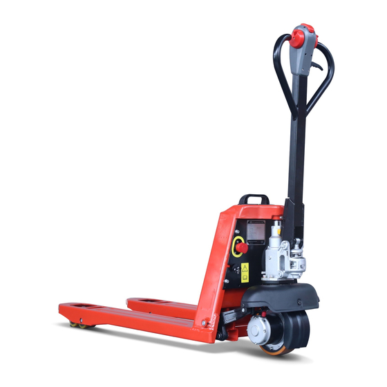
INFORMATION & SPECIFICATIONS 1.2 Introduction Name Name Control Lever Drive Motor Manual Lowering Lever Load wheel Hydraulic Station Charger Connector Drive Wheel Emergency Stop Switch Battery Plug REV. 08/2020... -
Page 15: Common Tools
INFORMATION & SPECIFICATIONS This series are electric pallet trucks. Its import- ant structure is as shown in Fig1128-00003SM. WARNING - Please refer to the nameplate for rated load capacity of the vehicle. - The vehicle can only be used on the level gro- und indoors, never use it on mezzanine or balcony area. -
Page 16: General Tightening Torques
INFORMATION & SPECIFICATIONS 1.4 General Tightening Torques Screws or bolts used on the truck are of 8.6 grade or higher performance level. When you are conducting truck maintenance, you can refer to Table 1.4.1 and Table 1.4.2 to select the suitable screws or bolts for replace- ment. - Page 17 INFORMATION & SPECIFICATIONS Table 1.4.2 Metric Screws/Bolts Tightening Torque Table (n•m) Performance Level 10.9 12.9 Nominal Diameter (mm) Proof Stress (MPa) 10~12 14~17 17~20 16~18 25~30 34~41 41~48 M8×1 17~20 27~32 37~43 43~52 31~36 49~59 68~81 81~96 M10×1 35~41 55~66 76~90 90~106 55~64...
- Page 18 INFORMATION & SPECIFICATIONS REV. 08/2020...
-
Page 19: Maintenance
2. MAINTENANCE... - Page 20 NOTE:...
-
Page 21: Overview
MAINTENANCE 2.1 Overview NOTE Only by performing regular vehicle maintenance Under harsh working conditions: such as, the and repair, can ensure the continuous and external temperature is too high or too low, reliable use of the truck. dusty, or implementing multiple shifts per day, Only specially trained and qualified personnel the maintenance and care interval should be shortened. -
Page 22: Maintenance
MAINTENANCE 2.2 Maintenance Regular inspection and maintenance under harsh conditions of use: 2.2.1 Cleaning Under harsh working conditions, especially: - Dusty environment Do not use flammable liquids to clean the - Corrosive environment truck. - Cold storage environment Before starting to clean, all necessary The maintenance intervals should be shortened security measures must be taken to prevent by half. - Page 23 MAINTENANCE Table 2.1 Inspection & Maintenance List Interval in days/months/years 60 d 90 d Interval in hours 1000 2000 Functions and Control Check the functions of the operation switches and display Check alarm system functions Check interlock switch functions Check the emergency switch functions Check the cables for damage and if the terminals are secure Check the lifting limit switch functions...
- Page 24 MAINTENANCE Table 2.1 Inspection & Maintenance List (Continued) Interval in days/months/years 60 d 90 d Interval in hours 1000 2000 Power Supply & Drive System Check the bearing bridge for damage or crack Check the travel speed Hydraulic System Check the functions of hydraulic system Check if the hoses, pipes and interfaces are fastened or sealed securely, and check if there is damage Check the cylinders for leaks...
- Page 25 MAINTENANCE Table 2.1 Inspection & Maintenance List (Continued) Interval in days/months/years 60 d 90 d Interval in hours 1000 2000 Lifting Mechanism Check and lubricate the moving parts of connecting A / L rod mechanism Check the lifting and lowering speed Other Check if the signs are clear and complete Check the chassis for cracks or damages...
-
Page 26: Lubrication
MAINTENANCE 2.2.3 Lubrication Please see Table 2.2 for the lubricants used in this truck. Lubricant CAUTION Improper operations may constitute hazards to the operator's health and life, as well as to The use and disposal of lubricants must be the surrounding environment. carried out in strict accordance with the manufa- cturer's regulations. - Page 27 MAINTENANCE Table 2.2 Lubricants Code Type Specification Amount Position Anti-wear hydraulic oil L-HM32 Hydraulic 180-200 mL Low temperature anti-wear System L-HV32 hydraulic oil (cold storage) Sliding surface Multi-purpose grease Polylub GA352P Appropriate amount (See Table 2.3) Grease 3#(MoS 110grams Gearbox Table 2.3 Sliding Surface Lubrication Table Code...
- Page 28 MAINTENANCE REV. 08/2020...
-
Page 29: Structure & Functions
3. STRUCTURE & FUNCTIONS... - Page 30 NOTE:...
-
Page 31: Structure & Functions
STRUCTURE & FUNCTIONS 3.1 Structure & Functions 3.1.1 Travel Switch Location: control handle; Function: to output travel speed signal to the drive controller; Description: when the vehicle is powered on, the travel switch is at Middle position; Note: Unserviceable. Horn Switch Key Switch Travel Switch 3.1.2 Horn Switch... -
Page 32: Crawl Speed Switch
STRUCTURE & FUNCTIONS 3.1.5 Crawl Speed Switch Location: control handle; Function: press the button and rotate the travel switch, the vehicle will travel at a very slow Crawl Speed speed; Emergency Reverse Switch Switch Description: the crawl speed switch is normally-open. -
Page 33: Led Lights
STRUCTURE & FUNCTIONS 3.1.8 LED Lights Charging Indicator Location: right of the chassis; Function: charging indicator displays the state of the charge; fault indicator shows the failure state of the truck; Description: under normal circumstances, fault indicator remain green; Note: Unserviceable. Fault Indicator 3.1.9 Charger Location: near the battery box;... -
Page 34: Fuse
STRUCTURE & FUNCTIONS 3.1.12 Fuse Location: main wiring harness; Function: overcurrent protection; Description: fusing current is 5A; Note: Unserviceable. Fuse 3.1.13 Interlock Switch Location: at handle joint; Function: the truck cannot be operated if the Interlock Switch interlock switch is not closed; Description: to prevent misuse of truck;... - Page 35 STRUCTURE & FUNCTIONS REV. 08/2020...
- Page 36 STRUCTURE & FUNCTIONS REV. 08/2020...
-
Page 37: Chassis System
4. CHASSIS SYSTEM... - Page 38 NOTE:...
-
Page 39: Load Wheel
CHASSIS SYSTEM 4.1 Load Wheel 4.1.1 Removal and Installation Removal Lift the forks of the vehicle carefully with lifting equipment; WARNING Make sure the lifting equipment is solid and secure, and the load capacity should be greater than the total weight of the vehicle. Single Wheel (see Fig1154-10003SM) Remove the coiled elastic cylindrical pin (1) within the wheel bracket with an ejector pin;... -
Page 40: Faults And Causes
CHASSIS SYSTEM 4.2 Cover CAUTION 4.2.1 Removal and Installation When installing, please apply appropriate amount of grease on the axle first. Removal (See Section 2.2.3 for specifications) Quality of tyres directly affects the stability and - Unscrew the three screws (1) and the screw driving performance of the device. -
Page 41: Lifting Mechanism
CHASSIS SYSTEM 4.3 Lifting Mechanism 4.3.1 Fork Inspection Lower the forks completely down: Lift the forks completely: The truck is equipped with batteries, the height The truck is equipped with batteries, the height from fork surface at center of load wheel to the from fork surface at center of load wheel to the ground (h1): ground (h2):... -
Page 42: Connecting Rod Adjustment
CHASSIS SYSTEM 4.3.2 Connecting Rod Adjustment 4.3.3 Removal and Installation Removal (See Fig1128-10004SM ) Fully lower the forks and switch off the power supply; - Fully lower the forks and switch off the power Lift the vehicle carefully with lifting equipment; supply;... - Page 43 CHASSIS SYSTEM CAUTION When replacing the long connecting rod, the connecting rod must be adjusted so that the fork surface height can reach the specified value. Installation - Install according to the reverse order of rem- oval. REV. 08/2020...
- Page 44 CHASSIS SYSTEM REV. 08/2020...
-
Page 45: Drive System
5. DRIVE SYSTEM... - Page 46 NOTE:...
-
Page 47: Drive Assembly
DRIVE SYSTEM 5.1 Drive Assembly Name Drive Assembly Electromagnetic Brakes Drive Motor Gear Case Gear Shaft Gear Gear Cover Driving Wheel Carbon Brush REV. 08/2020... -
Page 48: Removal And Installation
DRIVE SYSTEM 5.1.1 Removal and Installation - Unscrew the four screws (3) and the screw (4), then remove the assembly (5) from the Removal chassis; - Lower the chassis completely down, then cut - Unscrew the five screws (6) and remove the down the battery;... -
Page 49: Electromagnetic Brakes
DRIVE SYSTEM 5.2 Electromagnetic Brakes Remove the three mounting screws (1) with wrench. Remove the electromagnetic coil (2) and the dust cover (3); The truck is braked through electromagnetic brake. When the truck is powered off, the Remove the brake pads (4) and friction plates electromagnetic coil doesn't absorb the (5) by order;... -
Page 50: Faults And Causes
DRIVE SYSTEM 5.2.2 Faults and Causes - Identify if the electromagnetic coil is normal according to the readings of resistance on the multimeter. After the coil is energized, the Fault As shown in the following table: pressure plate does not absorb Resistance a. -
Page 51: Control Circuit Troubleshooting
DRIVE SYSTEM Mounting Screws Checks NOTE Three mounting screws in the brake may affect After a period of time of use, the springs may the normal absorption of pressure plates. be deformed due to the effect of radial force, Check if the mounting screws are bending due such case may result in abnormal air gap of the to a colliosion. -
Page 52: Drive Wheel
DRIVE SYSTEM 5.3 Drive Wheel - Knock out the drive motor (1, Fig1154-20008SM) of the assembly (2, Fig1128-20006SM); 5.3.1 Removal and Installation - Unscrew the nine screws (2,Fig1154- Removal 20008SM) with a wrench and remove the plate (3); Remove the drive assembiy (see Section - Knock out the oil seal (4) and gear ring (5);... -
Page 53: Drive Motor
DRIVE SYSTEM 5.4 Drive Motor - After replacing carbon brush, running opera- tion must be carried out to the carbon brush: This truck obtains drive force through DC motor. By running the motor with repeated lifting, letting the carbon brush to be fully running, making its surface smooth to fit the rotor. -
Page 54: Checking And Testing
DRIVE SYSTEM Circuit of drive motor Fault Motor smoking or burning smell Stator winding short circuit, motor Cause burnt Fault Excessive temperature rise a. Stator winding short circuit; b. Motor positive and negative electrodes with surface Cause oxidation, resistance increases and results in heating;... -
Page 55: Gearbox
DRIVE SYSTEM 5.5 Gearbox CAUTION 5.5.1 Removal and Installation Please add gear oil to the grease nipple on the gearbox cover (see Section 2.2.3 for specifica- The gearbox is installed under the drive tion and filling amount) mounting base. Remove the drive assembly from the gearbox 5.5.2 Faults and Causes (see Section 5.3.1);... - Page 56 DRIVE SYSTEM REV. 08/2020...
-
Page 57: Operating System
6. OPERATING SYSTEM... - Page 58 NOTE:...
-
Page 59: Control Lever
OPERATING SYSTEM 6.1 Control Lever Control lever is used to control the travel, emergency reverse switch (12) from the lower lifting, lowering, horn, crawl speed mode and cover (2); emergency reverse of the vehicle. - Disconnect the connection between the crawl speed switch (13) and elbow harness (4), Removal then remove the crawl speed switch from the... -
Page 60: Button Switch
OPERATING SYSTEM 6.2 Button Switch Testing Push button switch is the switch that makes Check if the push button switch circuit is the dynamic and static contacts ON or OFF to connected; achieve the switching of circuits through push- button drive mechanism. In the electrical control Carry out ON/OFF test to the push button circuits of this truck, the push button switch is switch with a multimeter:... - Page 61 OPERATING SYSTEM Emergency Reverse Switch (See Fig1128-30003SM) - Carry out ON/OFF test to the circuit between 1# and 13# with a multimeter: push button switch at original position, broken circuit; press the button , the circuit is conducted. Crawl Speed Switch (See Fig1128-30008SM) - Carry out ON/OFF test to the circuit between 1# and 90# with a multimeter:...
-
Page 62: Control Circuit Troubleshooting
OPERATING SYSTEM 6.2.4 Control Circuit Troubleshooting Horn Switch Control Circuit Start-stop Switch Control Circuit (Fig1128-30004SM) (Fig1128-30004SM) Check if the circuit is broken by using a multi- Check if the circuit is broken by using a multi- meter: meter: Set the multimeter to ON-OFF; Set the multimeter to ON-OFF;... - Page 63 OPERATING SYSTEM Crawl Speed Switch Control Circuit (Fig1128-30009SM) Check if the circuit is broken by using a multi- meter: Set the multimeter to ON-OFF; Check if #1 circuit (circuit between crawl speed switch and key) is conducted; Check if #8/#24/#90 circuit (circuit between emergency reverse switch and controller) is conducted.
-
Page 64: Travel Switch
OPERATING SYSTEM 6.3 Travel Switch Travel switch provides forward or backward in- put signals for the vehicle. 6.3.1 Removal and Installation See Section 6.1. 6.3.2 Faults and Causes Operate travel switch, the vehicle Fault cannot go forward or backward a. Travel switch failure; Cause b. -
Page 65: Control Circuit Troubleshooting
OPERATING SYSTEM 6.3.4 Control Circuit Troubleshooting Travel Switch Control Circuit (Fig1128-30007SM) Check if the circuit is broken by using a multi- meter: - Set the multimeter to ON-OFF; - Check if #1circuit (circuit between travel switch and controller) is conducted; - Check if #9/#10/#11 circuit (circuit between travel switch and controller) is conducted. - Page 66 OPERATING SYSTEM REV. 08/2020...
-
Page 67: Hydraulic System
7. HYDRAULIC SYSTEM... - Page 68 NOTE:...
-
Page 69: Overview
HYDRAULIC SYSTEM Hydraulic Oil The system pressure of the entire hydraulic system pressure is provided by hydraulic power Hydraulic oil for truck: unit system, which is used for lifting. While the Specifications: Anti-wear Hydraulic Oil L-HM32. hydraulic power unit is equipped with a relief valve to ensure that the entire system pressure * For cold storage: Low Temperature Anti-wear is always within the safety limits that can lift the... -
Page 70: Hydraulic Schematic Diagram
HYDRAULIC SYSTEM 7.1.1 Hydraulic Schematic Diagram REV. 08/2020... -
Page 71: Hydraulic Station
HYDRAULIC SYSTEM 7.2 Hydraulic Station 7.2.2 Component 7.2.1 Removal and Installation Removal - Remove the hydraulic station & control lever assembly; (See section 5.1.1) - Lower the manual lowering lever to the lowest position, then press the pressure release lever (1); - Remove the pull rod (2) from the pressure release lever (1);... -
Page 72: Cylinder
HYDRAULIC SYSTEM 7.3 Cylinder Upon removal, the damage to cylinder threads, oil port threads, cylinder cap threads, 7.3.1 Cylinder Removal Precautions piston rod surface and inner cylinder wall should be prevented. Before removing the cylinder, be sure to reli- In order to prevent piston rod from bending or eve the hydraulic circuit first, which is to lower deformation, support it wooden block when the lifting mast to the bottom. -
Page 73: Cylinder Installation Precautions
HYDRAULIC SYSTEM 7.3.2 Cylinder Installation Precautions 7.3.3 Removal and Installation All parts should be cleaned up before asse- See Section 7.2.1 mbly, then to be assembled after being dried;(during assembly, apply appropriate amount of hydraulic oil for lubrication) CAUTION The tools used to install the seals must Hydraulic oil may damage truck parts and cont- be made of soft metal or suitable plastic, aminate the environment. - Page 74 HYDRAULIC SYSTEM CAUTION If the piston rode or cylinder tube is damaged, please replace the entire cylinder. If the seals are aged or damaged, please replace the complete set of seals. REV. 08/2020...
-
Page 75: Hydraulic Troubleshooting
HYDRAULIC SYSTEM 7.4 Hydraulic Troubleshooting Fault Symptom Failure Causes Troubleshooting Measures a. Insufficient oil; 1. Check the hydraulic oil level. Noisy pump b. High viscosity of oil; 2. Replace the hydraulic oil. c. Hydraulic oil with foam; 3. See Fault 2. 1. -
Page 76: Hydraulic Symbol
HYDRAULIC SYSTEM 7.5 Hydraulic Symbol Symbol Description Symbol Description Tank Pipe end below liquid Check valve level Tank Cylinder Pipe end above liquid level Single-acting direction Manual Cylinder Filter Single-acting direction Service line (Supply line or return Manual Valve line) Two-way two-pass Control line (Drain line) -
Page 77: Electrical System
8. ELECTRICAL SYSTEM... - Page 78 NOTE:...
-
Page 79: Controller
ELECTRICAL SYSYTEM 8.1 Controller - Unscrew the two screws (3) with a wrench and remove the controller (4) and finning (5) from the plate. Installation - Apply appropriate amount of thermal grease on the back of controller; - Then install according to the reverse order of removal. -
Page 80: Controller Interface Function
ELECTRICAL SYSYTEM 8.1.2 Controller Interface Function J1 Interface - Continued Traction Controller (1212P) Pin No. Description J1-9 Lift Lockout J1-10 J1-11 J1-12 Backward J1-13 J1-14 Belly Switch J2 Interface (Handheld unit communication interface) J1 Interface J2 Interface J1 Interface Pin No. Description Pin No. - Page 81 ELECTRICAL SYSYTEM J3 Interface J3 Interface Pin No. Description Positive of electromechanical brake J3-1 coil. Negative of electromechanical brake J3-2 coil. Terminal stud Terminal stud Pin No. Description Negative of the motor. Positive of the motor. - Batt. +Batt. REV. 08/2020...
-
Page 82: Fuse
ELECTRICAL SYSYTEM 8.2 Fuse The entire vehicle is installed with two fuses altogether. When there is fuse failure, the truck may not be able to run properly due to that. Status Function Fuse 1 Fuse 2 Fuse 1 × Ο Fuse 2 100A Ο... -
Page 83: Checking And Testing
ELECTRICAL SYSYTEM 8.3 Emergency Stop Switch 8.2.2 Checking and Testing Emergency switch is used for emergency cut-off Checking of the power supply to all the control circuits. - Check the fuses for damage, check the connectors at terminal lugs for loosening or poor connection of leads. -
Page 84: Checking And Testing
ELECTRICAL SYSYTEM 8.3.3 Checking and Testing 8.4 Interlock Switch Checking 8.4.1 Removal and Installation - Check if the appearance of emergency switch its wiring harness are in good condition, and if the connectors are connected securely. Testing Check if the emergency switch circuit is con- ducted;... -
Page 85: Checking And Testing
ELECTRICAL SYSYTEM 8.4.3 Checking and Testing Checking - Check if the appearance of interlock switch and its wiring harness are in good condition, and if the connectors are connected securely; Testing - Check the status of the switch via the instru- ment;... -
Page 86: Battery
ELECTRICAL SYSYTEM 8.5 Battery 8.5.1 Removal and Installation - Unscrew the set screw (5) in the socket (9) Removal and remove the B+ cable and B- cable from the pin (7). - Turn off the power supply and lift the battery from the holder;... -
Page 87: Checking And Testing
ELECTRICAL SYSYTEM 8.5.3 Checking and Testing Checking - Check if the appearance of battery and battery holder are in good condition, and if the connectors are connected securely; Testing Check if the circuit of battery and battery holder is conducted; Short the port #80 and #81, measure the voltage between port #B- and #B+ with a multimeter: (see Fig1128-50006SM) -
Page 88: Led Lights
ELECTRICAL SYSYTEM 8.6 LED Lights 8.6.1 Removal and Installation Removal The entire vehicle is installed with three LED Lights including battery level indicator, charging - Remove the electrical mounting plate; (See indicator and fault indicator. Section 8.1.1) Battery level indicator shows battery residual - Disconnect the LED charging indicator con- capacity:... -
Page 89: Checking And Testing
ELECTRICAL SYSYTEM 8.6.3 Checking and Testing Checking - Check if the appearance of LED indicator its wiring harness are in good condition, and if the connectors are connected securely. Testing Check if LED indicator circuit is conducted; Energize the LED indicator with a voltage of 24V: If the light is on, then it is normal;... -
Page 90: Handheld Unit (Optional)
ELECTRICAL SYSYTEM 8.7 Handheld Unit (Optional) Turn on the key switch, pull out emergency stop switch, the display of handheld Handheld unit must be used together with con- unit will displays the Main Menu, but the troller, if necessary, it can be purchased from PROGRAMMER Menu is unselectable;... -
Page 91: Parameter Settings
ELECTRICAL SYSYTEM 8.7.3 Parameter Settings THROTTLE MENU CAUTION Paramete Setting Without the written permission of equipment Type manufacturer or its agent, it is strictly prohibit- ed to change any of the parameters in "PARA- PotHigh METERS". PotLow Traction Controller Parameter Settings Neutral Deadband Throttle Max DRIVE MENU... - Page 92 ELECTRICAL SYSYTEM HORN MENU COMPENSATION MENU Paramete Setting Paramete Setting Fault Beep IR Comp Reverse Beep Anti-Rollback Comp Beep Constant MISCELLANEOUS MENU Paramete Setting MOTOR MENU Sleep Paramete Setting Fault Code Type System Resistance Reset Drive Time Resistance Auto Comp Auto Comp Current Limit Speed Scaler Current Rating...
-
Page 93: Tester Menu
ELECTRICAL SYSYTEM 8.7.4 Monitor Menu The parameters in Monitor Menu are real- time presentation of the running status of the equipment. Traction Controller (1212P) Parameters Description Remark Temp Check the temperature of controller Display the current temperature ( ℃ ) Battery Voltage Check the voltage of storage battery Display the current voltage ( V ) -
Page 94: Controller Error Message
ELECTRICAL SYSYTEM 8.8 Controller Error Message to the vehicle, LED will twinkle and indicate the fault code; LED won’t restore to the extinguish- The error message can be obtained in two ways: ing state until the fault is eliminated. 1) By reading the appropriate display on the LED indicates two digit codes: for example, digit handheld unit ;... - Page 95 ELECTRICAL SYSYTEM Error Message BLINKS BLINKS EXPLANATION Possible cause Error text digit 1 digit 2 1. Battery voltage >31 volts. 2. Vehicle operating with OVERVOLTAGE battery voltage too high charger attached. FAULT 3.Intermittent battery connection. main contactor driver Off 1.Main contactor driver failed MAIN OFF FAULT fault open.
- Page 96 ELECTRICAL SYSYTEM Error Message BLINKS BLINKS EXPLANATION Possible cause Error text digit 1 digit 2 1.Motor voltage does not correspond to throttle request. HARDWARE motor voltage out of 2.Short in motor or in motor FAILSAFE range wiring. 3. Controller failure. ★ EE CHECKSUM EEPROM fault 1.
-
Page 97: Electrical Schematic Diagrams
ELECTRICAL SYSYTEM 8.9 Electrical Schematic Diagrams REV. 08/2020... -
Page 98: Cable Wiring Diagrams
ELECTRICAL SYSYTEM 8.10 Cable Wiring Diagrams Name Name Power Cable+ M2 Cable Controller + M1 Cable Controller - M2 Cable Fuse to Switch Cable Power Cable- M1 Cable REV. 08/2020... -
Page 99: Wiring Harness And Connectors
ELECTRICAL SYSYTEM 8.11 Wiring Harness and Connectors REV. 08/2020... - Page 100 ELECTRICAL SYSYTEM REV. 08/2020...
-
Page 101: Troubleshooting
9. TROUBLESHOOTING... - Page 102 NOTE:...
-
Page 103: Preparation Before Troubleshooting
TROUBLESHOOTING 9.1 Preparation Before Troubleshooting Park the truck on level ground and block the wheels with wooden wedges; Fully lower the fork and press the emergency stop switch. Turn off the key switch; Open the cover and check the controller. CAUTION Even if key switch is turned off, the controllers are still energized. -
Page 104: Troubleshooting Solutions Of Common Faults
TROUBLESHOOTING 9.2 Troubleshooting Solutions of Common Faults Table 9.1 lists the common faults that may occur and handling methods. Mainly consists of the following items: Table 9.1 Troubleshooting of Common Faults Fault Fault Symptom Troubleshooting Order * Troubleshooting Measures Power supply 1. - Page 105 TROUBLESHOOTING Table 9.1 Troubleshooting of Common Faults (continued) Fault Fault Symptom Troubleshooting Order * Troubleshooting Measures Hydraulic 1. The vehicle cannot a. Insufficient hydraulic oil 1) Lower the mast to the bottom, Failure lift check if the amount of oil in the b.
- Page 106 TROUBLESHOOTING REV. 08/2020...
-
Page 107: Appendix
APPENDIX... - Page 108 NOTE:...
-
Page 109: B Service Manual - Battery
B SERVICE MANUAL - BATTERY... - Page 110 NOTE:...
-
Page 111: B1 Lithium Battery
SERVICE MANUAL - BATTERY B1 Lithium-ion Battery B1-2 Use of Battery B1-2.1 Pre-use Checks B1-1 Safety and Warnings Check if the plug is tight. Unplugged may Do not short the positive and negative cause the output to be disconnected or the terminals of the battery. -
Page 112: B1-2.3 Charging
SERVICE MANUAL - BATTERY B1-2.3 Charging B1-3 Maintenance & Care Daily Maintenance When charging, only DC can be used. Con- nect the battery with proper charger for Charge the discharged battery; specification and size to avoid overload of circuit and interface. Check the appearance of batter for damage or leaks after the charging. - Page 113 SERVICE MANUAL - BATTERY Battery Fault Information If the controller detects a battery failure, flashes of LED battery level indicator represent battery failure information until the failure is remedied. Details of failure information are shown as below: Battery Fault LED Status The green light repeats in a cycle of flashing once in 1 Under-voltage of single cell second, pausing for 2 seconds and then flashing twice,...
- Page 114 SERVICE MANUAL - BATTERY REV. 08/2020...
-
Page 115: C Schedule
C SCHEDULE... - Page 116 NOTE:...
- Page 117 Operator's Daily Checklist Date Operator Truck No. Department Runtime Meter Reading Daily Check Items O.K.( √ ) Remark Drive Wheel Load Wheel Horn Lifting / Lowering Control Functions Optional Features Forward / Reverse Control Functions Steering control functions Braking Functions Check hydraulic system for leaks: cylinders, fittings, tubings, oil tank, etc.
Need help?
Do you have a question about the HPL152 and is the answer not in the manual?
Questions and answers