Table of Contents
Advertisement
Quick Links
Advertisement
Table of Contents
Troubleshooting

Subscribe to Our Youtube Channel
Related Manuals for EP Equipment CQD15SD


Summary of Contents for EP Equipment CQD15SD
- Page 1 CQD15SD Reach truck Operation Manual Original Instruction V1 03/2024...
- Page 2 Fig0000-00011OM EP EQUIPMENT CO.,LTD. is one of the world’s With business all over the world, EP has leading companies manufacture, design material thousands of employees and hundreds of agents handling equipment and provide related service. worldwide to provide our global customers with With over 100,000 square metres plant it produces prompt local service.
-
Page 3: All Rights Reserved
Foreword The present operation manual is designed to provide sufficient instructions for the safe operation of the industrial truck. The information is provided clearly and concisely. Our trucks are under ongoing development. EP reserves the right to alter the design, equipment and technical features of the system. - Page 4 Legal requirements for marketing Declaration EP EQUIPMENT CO., LTD. Address: No.1 Xiaquan Village, Lingfeng Street, Anji, Huzhou, Zhejiang We declare that the Industrial truck: according to this operation manual Type: according to this operation manual complies with the most recent version of Machinery Directive 2006/42/EC.
-
Page 5: Table Of Contents
Table of contents A Introduction...........................A1 1.1 Intended use ........................A2 1.2 Improper use ........................A3 1.3 Reach trucktruck handover ....................A3 B Truck description ........................B1 1.1 Application ..........................B1 1.2 Truck Assemblies .......................B2 1.2.1 Controls and Displays .....................B3 1.2.2 Instrument........................B5 1.2.3 Components ........................B10 1.3 Standard version specifications ..................B15 1.3.1Performance data for standard truck ................B15 1.3.2 Dimensions ........................B25 1.4 Identification points ......................B27... - Page 6 Table of contents 1.4.2 Open the cover ....................G13 Decommissioning the trucks................G18 1.5.1 Prior to decommissioning ..................G18 1.5.2 Restoring the truck to operation after decommissioning ........G18 1.6 Final decommissioning, disposal ................G18 Troubleshooting ......................H1 Appendix ..........................I1 Lead-acid battery operating instructions ................I2 1.1 Safety and warning ....................I2 1.2 Use of Battery ......................I3 1.2.1 Pre-use Checks ....................I3...
-
Page 7: A Introduction
Introduction The fork lift truck is designed to pick up and move materials. The basic lift truck has a lift mechanism with forks on the front to engage the load. The lift mechanism lifts the load so that it can be moved and stacked. In order to understand how the lift truck can pick up a load, you must first know some basic things about the lift truck. -
Page 8: Safety Devices And Warning Labels
It must be used, operated and maintained according to the information in this operation manual. Any other uses are outside the design envelope and can lead to injury to persons or damage to equipment and property. Above all, overloading caused by excessively heavy or unbalanced loads must be avoided. -
Page 9: Intended Use
Intended use • The industrial truck is used for moving and lifting the loads indicated on the load capability chart. • Damages and other defects to industrial trucks or to attachments must be reported to the supervisor immediately. Industrial trucks and attachments which are not safe to operate may not be used until they have been properly repaired. -
Page 10: B Truck Description
B Truck Description Application It is an battery-powered truck. With maximum economic efficiency, safety and driving comfort. The series is a three wheel electric side seat, clear view reach truck. It is designed for internal and external use to lift and transport goods. Open bottom pallets or pallets with transverse boards can be lifted inside or outside the area of the load wheels or roll cage. -
Page 11: Truck Assemblies
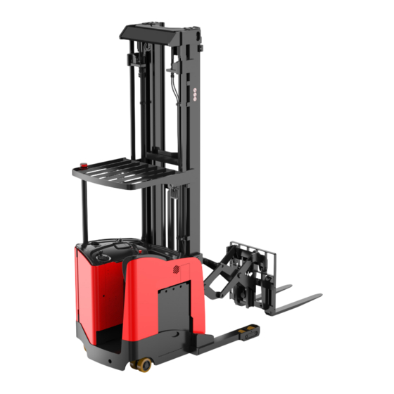
Truck Assemblies Fig3316-00001OM Caster Mast Headlight Drive wheel Forks Operator's compartment Warning light Load backest Overhead guard Reach Mechanism Basearms Rearview mirror Load wheels Battery Chassis REV. 03/2024... -
Page 12: Controls And Displays
1.2.1 Controls and Displays Component Function Item Switches control current on and off. Removing Key switch the key prevents the truck from being switched on by unauthorized personnel. Handbrake switch Apply and release the truck This switch controls the optional work lights when Headlight switch installed. - Page 13 Sideshift Lower Forward Tilt Reach/Retract Horn Lift Backward Item Component Function Travel is activated by moving the control handle in the direction of travel. Pushing the control handle away from operator provides Forward Travel. Pulling the control handle toward operator provides Reverse Travel. The travel speed, for both forward and reverse directions, is proportional to the distance the handle is moved;...
-
Page 14: Instrument
1.2.2 Instrument (2)KEYBOARD BUTTON:ROLL DOWN (1)KEYBOARD BUTTON:ROLL UP (4)KEYBOARD BUTTON:SET DOWN (*)KEYBOARD BUTTON:ENTER (3)KEYBOARD BUTTON:SET UP (5)KEYBOARD BUTTON:OUT Main interface displays instructions: Speed display Number is the speed value, and the speed unit is shown below. Km/h or MPH can be selected by parameters. Parameter position is: DISPLAY xxx---Parameter Set---Speed Unit Battery status indicator... - Page 15 Running time display Fig0000-00257OM Fork height display Fig0000-00254OM Accelerator output >> >> >> >> Fig0000-00258OM Fault display area 1 fault code 2 failure node 3 troubleshoot ERROR START-UP ORDER Fig0000-00255OM When there is a fault at the same time, the meter has a buzzer to alert, and the corresponding failure icon indicates, if the truck failure, the failure icon is displayed next to the vehicle, if the lithium battery failure, the failure icon shows the power bar, the icon.Such as graphic: Fig0000-00259OM...
- Page 16 Proportional lift indication >> >> >> >> Fig0000-00256OM Red pedal(CAN brake)indicates [display only with this configuration] Fig0000-00279OM Fig0000-00280OM Fig0000-00281OM Fig0000-00282OM Gray: no output Green: low output Orange: medium output Red: high output Where, if there is a fault or interruption of CAN message on the red pedal, the icon will flash to remind Lithium battery related instructions [only for lithium battery truck] Fig0000-00278OM...
- Page 17 Drivability Settings Low Speed mode Medium speed High speed mode mode Fig0000-00272OM Fig0000-00274OM Fig0000-00276OM Slow acceleration Adding rate Fast rate acceleration rat Fig0000-00275OM Fig0000-00277OM Fig0000-00273OM Which can be set through the instrument parameters, gear selection: DISPLAY xxx----Parameter Set----SPE Mode Option) 0(default):Press 1 to switch the speed and acceleration rate at the same time.
- Page 18 Current controller failure display When the controller has a failure, enter the corresponding controller node, the top index column display 1.Current controller node 2.Current controller fault interpretation Fig0000-00267OM No failure, menu index display When the controller is trouble-free, enter the corresponding controller node and the top index column will be displayed 1.
-
Page 19: Components
1.2.3 Components Overhead guard The overhead guard protects the operator against injury from falling objects. It must Overhead guard Headlights have sufficient impact strength. Its gap is used to lift battery. Do not use the forklift without the overhead guard. Chassis The chassis, in conjunction with the counterweight, forms the supporting base... -
Page 20: Operating Attachments
Warning light Press the caution light button, the caution light will flash. WARNING When start the truck, you must press the warning light button to keep the caution light on. Warning light Cushion position witch Pull the switch to adjust the cushion up and Cushion down position switch... -
Page 21: Standard Version Specifications
1.3 Standard Version Specifications Technical specification details in accordance with VDI2198. Technical modifications and additions reserved. 1.3.1 Performance data for standard truck Distinguishing mark Manufacturer Model designation CQD15SD Drive unit Electric Operator type Standing rated capacity Load center distance Load distance, centre of... - Page 22 3.3.1 Tyre size, steering mm Φ127× 98 wheels Tyre size, caster mm Φ178×73 wheels(diameter×width) 3.5.1 Wheels, number driving/ mm 1×,2/4 steering (x=drive wheels) 3.6.1 Track width, front,driving side mm 721.5 3.7.1 Track width,rear,loading side mm 1006 Dimensions Ti l t o f m a s t / f o r k c a r r i a g e α/ β...
- Page 23 4.31 Ground clearance, laden, below mast 4.32 The minimum ground clearance of frame 4.34.1 Aisle width for pallets 1000 3125 (Table 3) × 1200 crossways 4.34.2 Aisle width for pallets 800 × 3195 (Table 3) 1200 lengthways 4.35 Turning radius 1945 4.37 Length across wheel arms...
- Page 24 Performance data Travel speed, laden/ unladen km/h 11/12 Lifting speed, laden/ unladen m/ s 0.45/0.5 Lowering speed, laden/ m/ s 0.5/0.5 unladen Reaching speed, laden / m/ s 0.2/0.23 unladen Max. gradeability, laden/ 10/12 unladen 5.10 Service brake type Electromagnetic Park brake type Electromagnetic Electric-engine...
- Page 25 Table 1 Mast Type Lift height(mm.) Service weight (with battery)kg. 6500 4390 6860 4425 7000 4440 3-stage 7500 4490 7600 4500 8000 4540 8150 4555 8500 4590 8660 4305 9000 4640 9300 4670 9500 4690 10000 4740 10160 4755 10500 4790 10700 4810...
- Page 26 Table 2 Lift height(mm.) Height, mast Free lift (mm.) Height, mast lowered(mm.) extended(mm.) h2(*) h4(*) 6500 2965 1900 1900 7465 7465 6860 3085 2020 2020 7825 7825 7000 3130 2070 2070 7960 7960 7500 3295 2240 2240 8260 8260 7600 3330 2270 2270...
- Page 27 Table 3 pallet dimensions Width of the Recommended right-angle stacking aisle Recommended mm (L× W) right-angle fork length( width utilizing shelf space fork length( mm) stacking aisle Ast2(mm) Ast1 (mm) 1200 × 1200 3090 1200 2920 1070 1200 × 1100 3060 2920 1200 ×...
-
Page 28: Dimensions
1.3.2 Dimensions REV. 03/2024... -
Page 29: Identification Points
1.4 Identification points 左视图 后视图 右视图 Left Back Right Q (kg) VEHICLE NAME Q (kg) MODEL NO. SERIES NO. DATE OF BUILD TRUCK WEIGHT WITH BATTERY LOAD CAPACITY LOAD CENTER TRUCK WEIGHT WITHOUT BATTERY VOLTAGE DRIVE OUTPUT MAX BATTERY WEIGHT MIN BATTERY WEIGHT ALT CAPACITY MAX CAPACITY... - Page 30 Truck data plate For queries regarding the truck or ordering spare parts please quote the truck serial number. Item Description Item Description PRODUCT NAME RATED CAPACITY MODEL TYPE LOAD CENTER SERIAL NO. MAX BATTERY WEIGHT MANUFACTURE DATE MIN BATTERY WEIGHT UNLADEN MASS UNLADEN MASS WITHOUT BATTERY BATTERY VOLTAGE...
- Page 31 The load capability chart The capacity plate gives the capacity (Q) of the truck in kg for a vertical mast. The maximum capacity is shown as a table with a given load centre of gravity D (in mm) and the required lift height H (in mm). The capacity plate of the truck indicates the truck's capacity with the forks as originally supplied.
-
Page 32: C Safety
C Safety Before Operation Before using the truck, inspect the work area. It should be neat, well lit, adequately ventilated, and free from hazardous material. Aisles and roadways should be unobstructed and well ma- rked. Operators must know the classification for the truck and use the truck only in permissible areas. - Page 33 4.Stop using the reach truck when it malfunctions Whenever malfunctions arise, you must stop using forklift, hang a sign of “danger” or “malfunction” and take off the key, then report the malfunction immediately. only after the malfunction is eliminated, you may use the forklift. 5.
- Page 34 11. Prohibit sudden stops, starts or sharp turns Operate the controls smoothly. Avoid sudden stops, starts or sharp turns. It is dangerous to make a sudden brake. for it may cause the truck to overturn. 12.Focus on the travelling route· Pay attention to the route of the truck, be sure to keep a clear view of it and look in the direction of travelling.
- Page 35 20. Use proper attachments We afford all types of attachments, such as rotating roll clamp, bale clamp, side shifter, and crane jib. You should refit the truck under ours license if you want(Modifications to the truck must be authorized by the manufacturer). Only specialists are permitted to fit the attachments and connect the energy supply for power-driven attachments.
- Page 36 26.Don’t tilt the mast with load high Use minimum forward and backward tilt when stacking and unstacking loads. Never tilt forward if load is over stack or at low lift height. When stacking loads on a high place, once make the mast vertical at a height of 15 to 20 cm above the ground and then lift the load farther.
- Page 37 In the case of tip-over The stability of your truck is ensured if used properly and as intended. But once it tips over during unapproved applications or incorrect operation, always follow the instructions below: • Stay buckled up; • Don’t jump; •...
- Page 38 Small loads should be carried on a pallet and not placed directly on the forks. 35.Avoid lifting loads on a grade Never lift loads with the truck inclined. Avoid loading and unloading on a grade. 36. Never lift a load over anyone Never permit anyone to stand on or walk under upraised forks or other attachments if equipped.
- Page 39 41.Residual risks In spite of careful work and compliance with all applicable and regulations, the possibility of other dangers when using the industrial truck cannot be entirely excluded. Residual dangers can include: Escape of consumables due to leakages or the rupture of lines, hoses or containers; •...
-
Page 40: Battery Safety
The design and manufacture of electrical element comply with the low voltage standard 2006/95/EC. Noise emission level CQD15SD:75dB(A) Noise will be according with EN12053:2001 and 2000/14/EC. Sound pressure level on the operator’s position is lower than 75dB(A), measurement uncertainty is 1.5dB(A). -
Page 41: Emc (Electromagnetic Compatibility)
EMC-Electromagnetic compatibility Electromagnetic compatibility (EMC) is a key quality feature of the truck. • EMC involves limiting the emission of electromagnetic interference to a level that ensures the troublefree operation of other equipment in the environment. Ensuring sufficient resistance to external electromagnetic interference so as to guarantee •... -
Page 42: D Transport And Commissioning
D Transport and Commissioning Transport The truck must be securely fastened when transported on a lorry or a trailer. The lorry / trailer must have fastening rings. • To fasten the truck pull the tensioning belt (3) through the guide on the overhead guard brace and attach it to the fastening rings. -
Page 43: The Structure And Stability Of Truck
• Reach the mast fully back.; • Fix two double loop slings around the mast upper cross membe; • Protect the truck parts in contact with the slings. CAUTION • After hanging the sling on the lifting hook, the safety lock must be fastened. •... - Page 44 The stability of the lift truck is determined by the location of its CG, or if the truck is loaded, the combined CG. The lift truck has moving parts and therefore has a CG that moves. The CG moves forward and back as the forks are extended or retracted.
-
Page 45: Using The Truck For The First Time
1.4 Using the truck for the first time Packaging During delivery of the truck, certain parts are packaged to provide protection during transport. This packaging must be removed completely prior to initial start.up. NOTE The packaging material must be disposed of properly after delivery of the truck. Only operate the trucks with battery current. -
Page 46: E Operation
E Operation Run the truck Checks and operations to be performed before starting daily work. • Visually inspect the entire truck (in particular wheels) for obvious damage. • Visually inspect the battery attachment and cable connections. • Check the mast , load backrest and forks for visible damage such as cracks. •... - Page 47 Steering Use Steering Disk to steer the truck in the required direction.The drive wheel position is indicated in the driver’s display. WARNING Travel slowly when turning. Lift trucks can tip over even at very slow speeds. The combination of speed and the sharpness of a turn can cause a tipover. A lift truck is less stable when the forks are raised, with or without a load.
-
Page 48: Loading
• With the reversing brake While the truck is travelling press the travel switch (4). It switches to the opposite travel direction and the truck decelerates through the traction current controller until it starts to move in the opposite direction. •... - Page 49 If the weight of the load is not centered between the forks, the load can fall from the forks when you turn a corner or hit a bump. An off center load will increase the possibility of the truck tipping over to the side.
- Page 50 WARNING Keep yourself and all others clear of the lift and reach mechanisms. Never allow anyone under or on the forks. NEVER put hands, arms, head or legs through the mast or near the carriage or lift chains. This warning applies not only to the operator, but also a helper.
- Page 51 How to Engage and Disengage a Load 1. Avoid fast starts. Sudden movement can cause the lift truck to tip. People can be hurt or killed and material can be damaged. Approach the load carefully. Make sure that the truck is perpendicular to the load.
- Page 52 3. Put the load on the floor. If the lift truck is equipped with a tilt function tilt the carriage forward to permit smooth removal of the forks. Carefully move the lift truck backward to remove the forks from under the load. 4.
- Page 53 5. To put the load on a stack, align the lift truck with the stack. Lift the load to eye level and then tilt the load forward until it is level. Raise the load higher than the point where it will be placed. Do not raise the load to a point below where the load is to be placed and jog the load up into position.
-
Page 54: Manual Lowering
Stopping Stop the lift truck as gradually as possible. Hard braking and wheel sliding can cause the load to fall off of the forks and damage the load or hurt someone. Gradually stop the lift truck using plugging. Manual Lowering DANGER Always verify that no one is under or near the lift mechanism or load during the manual lowering procedure. -
Page 55: Operating The Truck Without Its Own Drive System
Operating the truck without its own drive system If the truck has to be moved after a failure has rendered it immobile, proceed as follows: • Set the emergency stop switch “OFF”. • Set the key switch “OFF” and remove the key. -
Page 56: Definition Of Direction Of Travel
DANGER Do not raise the truck more than necessary. Only raise the drive wheel just clear of the floor. One person should be on the truck being towed to operate the brakes if necessary. Definition of direction of travel This manual defines the direction of travel as follows: (A) = Travel with forks trailing (B) = Travel with forks leading... -
Page 57: Operator Daily Checklist
1.9 Operator daily checklist Operator's Daily Checklist Daily Check Items O.K.(√) Remark Check the truck free from accumulation of grease, dirt, and other possibly combustible materials Check the condition of caster,load wheels Check chassis, bodywork,Dash Display, Horn, Lights, Fuses and fittings Check the condition and function of the cushion. -
Page 58: F Battery Maintenance & Charging & Replacement
Battery Maintenance & Charging & Replacement Battery type & dimension Battery type & dimension as follow: Dimension Battery Voltage/ rated Charging Tuck type Charger type capacity (mm) time(h) Lead-acid 100A CQD15SD 48V/700AH 1025*500*710 battery lithium-ion 150A CQD15SD 48V/405Ah 1025*500*710 battery lithium-ion 200A CQD15SD 48V/560Ah 1025*500*710... -
Page 59: Charging The Battery
Charging the battery Normal working conditions • No rain or snow, no conductive dust, no explosion hazard; • The altitude does not exceed 1000 meters; • The relative humidity of the air is not more than 95% (when the medium temperature is 20±5°C);... - Page 60 WARNING The battery charging station should be plugged into a standard 380V, 3-phase, 50/60Hz walloutlet.The battery plug and socket may only be withdrawn or connected when the main switch and the charging equipment are switched off. Maximum input power is 13.3KW. Please strictly implement the above data to prevent equipment damage and accidental risks such as fire.
-
Page 61: Battery Removal And Installation
Battery removal and installation • Parking the trcuk securely(see chapter E section1.4) ; • Unplug the battery plug (2) • Place the battery plug or the battery cable in such a way that they will not get caught on the truck when the battery is removed. -
Page 62: G Truck Maintenance
Truck Maintenance Operational safety and environmental protection The servicing and inspection operations contained in this chapter must be performed in • accordance with the intervals indicated in the service checklists. Only use original spare parts that have been certified by our quality assurance. •... -
Page 63: Servicing And Inspection
Settings When repairing or replacing hydraulic, electric or electronic components or assemblies, always note the truck specific settings. Servicing and inspection Thorough and expert servicing is one of the most important requirements for the safe operation of the industrial truck. Failure to perform regular servicing can lead to truck failure and poses a potential hazard to personnel and equipment. -
Page 64: 1Maintenance Checklist
1.3.1 Maintenance Checklist ● Maintenance interval Clean the reach truck if necessary. Check the time and date settings on the display Before unit; adjust if necessary. starting Check for error codes on diagnostic software and maintenance delete. work: Check battery state of charge ●... - Page 65 ● Maintenance interval ● Chassis, tilt cylinders and reach cylinders : Check fastening. ● Check the counterweight, motors, chassis, speed Frame and reduction gearbox, overhead guard and steering axle installation fastenings. ● Lubricate the overhead guard pin shaft. ● Check and lubricate the other pins and swivel points. ●...
- Page 66 ● Maintenance interval ● Check the cylinders for leaks. ● Check the hydraulic hoses and pipes for damage ● Check the hydraulic oil level. Hydraulics ● Clean or replace the hydraulic oil. ● Replace the air, pressure and suction filters. ●...
-
Page 67: Lubrication Points
1.3.2 Lubrication Points Lubricant Improper operations may pose hazards to the operator's health and life, as well as to the surrounding environment. When storing or adding lubricant, use clean containers. It is strictly forbidden to mix different types and specifications of lubricants (except for those can be mixed under clear statement). CAUTION The use and disposal of lubricants must be carried out in strict accordance with the manufacturer's regulations. - Page 68 Table 2.2 Lubricants Code Type Specification Amount Position Anti-wear hydraulic oil L-HM32 Hydraulic See Table 2.3 Low temperature anti-wear System L-HV32 hydraulic oil (cold storage) Sliding surface Multi-purpose grease Polylub GA352P Appropriate amount (See Table 2.4) Heavy duty gear oil 80W-90 GL-5 3.5L (Align with oiling port) Gearbox Table 2.3 Application Amount of...
- Page 69 Table 2.4 Sliding Surface Lubrication Table Code Position Steering gear Caster Fork carriage Scissors assembly Steel channel and rollers REV. 03/2024...
-
Page 70: Maintenance Instructions
Maintenance Instructions How to Raise the Load Wheels 1.4.1 1.Release the brake pedal to apply the brake. Put blocks on both sides (front and back) of the drive/steer tire and the caster wheels to prevent movement of the lift truck. 2.Use an overhead crane and web sling under the base arms at the mast to raise the load wheels. -
Page 71: Installation And Commissioning
WARNING Make sure the lifting equipment is solid and secure, and the load capacity should be greater than the total weight of the vehicle. WARNING When replacing wheels, be sure that the truck won't tilt. Installation and Commissioning Install according to the reverse order of removal; Turn the wheel to see if it is rotating smoothly, and if there is blocking or not;... -
Page 72: Installation
Caster Removal Unscrew three bolt (1), remove the cover (2), Loosen the nut (19) knock out the snap ring (18) and remove the caster(14). Installation Install according to the reverse order of removal; WARNING Changes in steering and traction responses must be reported to a supervisor immediately. As drive tires wear from normal use, the caster assembly will periodically need to be adjusted to maintain proper support. - Page 73 Drive Wheel Removal and Installation Removal Lift the vehicle carefully with lifting equipment through the lifting holes at at front and back; WARNING Make sure the lifting equipment is solid and secure, and the load capacity should be greater than the total weight of the vehicle.Lifting height of not more than 300mm, to prevent the hazards to the maintenance personnel working under the...
-
Page 74: Open The Cover
1.4.2 Romove the cover • Unscrew the Star-shaped handle (1) and open the side cover(2). • Unscrew the screw and remove the steering disk(3). • Unscrew the six screws(4) and remove the Upper cover(5). Check the hydraulic oil level NOTE Open the drive unit compartment door and inspect the hydraulic system for leaks and damaged or loose components. - Page 75 Visually check the hydraulic oil level when the oil is at operating temperature, the carriage is lowered, the reach mechanism retracted and the key switch is in the OFF position. Add hydraulic oil only as needed. Be careful not to over fill. •...
-
Page 76: Fork Removal
Adjust and replace forks Adjust fork distance In order to guarantee safe operation of picking loads, before operation, adjust the fork distance to proper position according to the tray dimension. Procedures – Pull the fork locating pin upward (1), and rotate180°... - Page 77 Lift Chain Inspection and Lubrication During normal operating conditions, inspect and lubricate the lift chains every 450 to 500 hours. If operating in corrosive or extreme working conditions, inspect more frequently. When inspecting, check for: rust and corrosion, cracked plates, raised or turned pins, tight joints, excessive wear, and worn pins and holes.
-
Page 78: Check Transmission Oil Level
Check the electrical fuses • Prepare the truck for maintenance and repairs. • Open the battery hood. • Check condition and rating of the fuse(2) in accordance with your parts manual or service manual. WARNING When replacing for a new fuse, please choose the fuse of same capacity as the old one. -
Page 79: Decommissioning The Trucks
Decommissioning the trucks If the reach truck is to be used for over 2 months, it must be parked in a frost-free, clean and dry location. On decommissioning the truck must be jacked up so that all the wheels are clear of the ground. -
Page 80: H Troubleshooting
H Troubleshooting This chapter is designed to help the user identify and rectify basic faults or the results of incorrect operation. When locating a fault, proceed in the order shown in the table. If the fault cannot be rectified after carrying out the remedial procedure, notify the manufacturer ’ s service department ,as any further troubleshooting can only be performed by specially trained and qualified service personnel.The manufacturer has a customer service department specially trained for these tasks. - Page 81 Fault Fault Symptom Troubleshooting Order * Troubleshooting Measures Hydraulic 1. The vehicle 1. Pump motor does not work: 1. Pump motor does not work: Failure cannot lift a.The foot switch don't depress for 1)Check whether the foot switch is CQD12R/RF depressed.
- Page 82 Fault Fault Symptom Troubleshooting Order * Troubleshooting Measures Lift Failure 3. Slow Lifting of a. Overload 1) Refer to the rated capacity Vehicle marked on the nameplate; b. Hydraulic pipeline leakage 2) Check the pipe and hydraulic c. Valve failure: components for oil leaks;...
- Page 83 Fault Fault Symptom Troubleshooting Order * Troubleshooting Measures Other Failures 1. Lights do not light a. Light failure or circuit not 1) Check the light and its circuit conducted connection; 2. Horn does not a. Horn switch or its circuit 1) Check the horn button and its sound connection failure...
-
Page 84: Appendix
APPENDIX REV. 03/2024... -
Page 85: Lead-Acid Battery Operating Instructions
1 Lead-acid battery operating instructions 1.1 Safety and Warnings When operating on battery, you must wear protective glasses and protective clothing! Electrolyte contains sulfuric acid and is highly corrosive. If it accidentally comes into contact with the skin, wash immediately with plenty of water, if the situation is serious, immediately seek medical advice. -
Page 86: Use Of Battery
1.2 Use of Battery 1.2.1 Pre-use Checks Check if the battery status is normal and also check for mechanical failures; Connect the battery connectors, make sure the contact is solid, the electrodes are connected properly, otherwise may cause damage to the battery, truck or charger; Check if the electrode bolt of each battery interface is tightened;... -
Page 87: Temperature
1.2.4 Temperature Rated temperature of electrolyte is 30 °C. If the temperature is too high, it will reduce the service life of the battery; too low may reduce the battery capacity. When the temperature reaches the limit temperature of 55 ° C, it is prohibited to run the battery. 1.3 Maintenance &... -
Page 88: Monthly Maintenance
There are two types of battery filler proper electrolyte cap used on battery cell: 合适的电 liquid leveL 解液液位 1) Filler cap with buoy Battery Add distilled water, red buoy will 电瓶 float until while rod appears under the red scale. WARNING Batteries can be hazardous when being handled and maintained. - Page 89 CAUTION After being fully charged, if the voltage of battery cell is lower than 1.85V or the specific gravity of electrolyte is less than 1.05, then that battery cell has been damaged and needs to be replaced. As for a group of normal batteries, when the battery is discharged for 80% (the instrument alarms and prompts low battery, you should recharge in a timely manner), the open circuit voltage should be around 1.93V, specific gravity of electrolyte (under 30°C) should be around 1.14.
-
Page 90: Care
1.3.4 Care 1. Keep it clean Battery surface should be clean and dry to prevent the occurrence of leakage currents; Battery cables, terminals and connectors mu-st be tightened and clean, a small amount of special grease should also be applied. WARNING •Do not use a dry cloth or fabric to clean the surface of the battery, so that to prevent the occurrence of static electricity, resulting in explosion;... - Page 91 Battery Fault Analysis Fault Negative Phenomena Cause Handling Methods Insufficient 1. Low static voltage 1. Charger voltage and 1. Adjust and repair the Battery 2. Low density, cannot meet current charger Charge the requirements after are set too low 2. Battery supplemental being 2.
- Page 92 Battery Fault Analysis Fault Negative Phenomena Cause Handling Methods Electrode 1. Battery capacity drops 1. Insufficient initial charge 1. Over-discharge method plate during normal discharge 2. Long time of storage under 2. Repeated charging sulfation 2. Density drops to be lower the state of discharge method than normal value...
- Page 93 Battery Fault Analysis Fault Negative Phenomena Cause Handling Methods Battery 1. Low static voltage below 2V 1. Electrode plate deformed and Battery needs to be replaced 2. Electrolyte density is too low short circuit Short 3. High temperature during 2. Spacer missing or broken Circuit charging during assembly...
-
Page 94: Appendix
APPENDIX J Lithium battery operating instructions REV. 03/2024... -
Page 95: Lithium Battery Use And Maintenance Manual
Lithium Battery Use and Maintenance Manual Information on the conformity of lithium-ion batteries The manufacturer of the lithium-ion battery and EP group provider declares that: the lithium- ion battery conforms with the provisions of the following EU directive 2014/30/EU in accordance with EN12895. This declaration of conformity with EU directives applies only to battery use that conforms to the recommendations described in the operating instructions. -
Page 96: Safety And Warning
Accessories Do not use a charger that is not released by your manufacturer for lithium-ion battery. BMS (Battery Management System) The battery is permanently monitored by the BMS (Battery Management System). This provides the communication with the truck. The BMS continually monitors items such as the cell temperature, the voltage and the charge status of the cells. - Page 97 •Explosion or fire disaster is likely to occur; avoid short circuit! •Keep the battery away from all fire sources, heat sources and flammable or explosive materials. Fig0000-00004OM •Don’t knock over the storage battery! •Using lifting and delivery devices as specified. Prevent the storage battery cell, interface and connection cable from being damaged by the lifting hook! •If the materials leak out, do not inhale the fumes.
-
Page 98: Hazard Of Faulty Or Discarded Battery
1.3 Hazard of faulty or discarded battery Please monitor the battery status when in use and in storage. If you find any broken batteries, electrolyte leakage, abnormal expansion or pungent odors due to shipping damage or abnormal vibration, please stop use immediately and keep at least a 5 meter perimeter around the effected batteries. -
Page 99: Instructions
Instructions Before the first use, charge battery completely with original charger. • The lithium battery should be used at an ambient temperature of 0 ~ 40°C, do not use or • store the battery near a fire source/heat source where the temperature exceeds the safety range;... - Page 100 Name Description When all 10 cells are on, it indicates that the battery is full; When the first cell and the second flash alternately, it Energy display indicates that the battery is low and must be charged. The battery remaining charge is displayed; “100%” indicates that the battery is fully charged.
-
Page 101: Lithium Battery Nameplate
Name Description Maximum cell Maximum value of cell voltage voltage No. of cell Identification No. of the cell with maximum voltage. Minimum cell Minimum value of cell voltage voltage Cell No. of minimum cell Identification No. of the cell with minimum voltage. voltage 1.4.2 Lithium Battery Nameplate... -
Page 102: Charging
1.4.3 Charging • This battery can only be charged with the vehicle-specific charger, other chargers may cause battery damage. • The normal charging temperature range of the battery is: 5°C ~ 40°C, please do not charge in the environment beyond the normal temperature range; •... -
Page 103: Storage
Storage Try to ensure that the battery or battery pack's power is ≥50% before long-term storage as the • battery has the function of self-discharge, be sure to charge the battery once every 2 months to ensure the battery power is ≥50%; The battery should be stored in a temperature environment of 0°C~40°C;... -
Page 104: Instructions For Disposal
NOTE It is recommended that the original packaging is kept for any subsequent dispatch. A lithium-ion battery is a special product. Special precautions should be taken when: Transporting a truck equipped with a lithium-ion battery • Transporting only the lithium battery •... -
Page 105: Common Problems And Solutions
WARNING Don't bump, handle gently. Used cells and batteries are recyclable economic goods. In accordance with the mark showing a crossed rubbish bin, these batteries may not be disposed of as domestic waste. Return and / or recycling must be ensured as required by the Batteries Act (Act regarding the commissioning, return and environmentally responsible disposal of batteries and accumulators). -
Page 106: Service
1.9.Service Daily Maintenance No. Maintenance content Method of operation Note Frequency Check if battery capacity Check instrumentation Make sure the battery is Everyday is too low SOC display not stored without charge for a long time. If the battery system needs to be put on hold for a long time, it is best to keep the battery in half power state... - Page 107 No. Maintenance content Method of operation Note Frequency Whether the external Perform a visual Make the wiring harness weekly wiring harness has worn, inspection fixed well imprint, creases and exposed line core Check that the surface of No dust, no water, no Clean surface if you found weekly lithium-ion battery looks...
Need help?
Do you have a question about the CQD15SD and is the answer not in the manual?
Questions and answers