
Subscribe to Our Youtube Channel
Related Manuals for EP Equipment EPT20-15ET


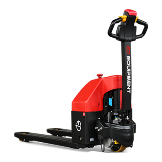
Summary of Contents for EP Equipment EPT20-15ET
- Page 1 Operation Manual EPT20-15ET EPT20-18EA EPT20-15ETL EPT20-15EHJ EPT20-15ET2 EPT18-EHJ EPT20-ET Original Instruction Part No.508000004646 V4 07/2020...
- Page 2 Fig0000-00011OM EP EQUIPMENT CO.,LTD. is one of the world’s With business all over the world, EP has leading companies manufacture, design thousands of employees and hundreds material handling equipment and provide related of agents worldwide to provide our global service. With over 100,000 square metres plant customers with prompt local service.
- Page 3 Preface Thank you for buying our products. The manual will show you the way of correctly using the truck as well as relevant preventive maintenance and safety operation. The truck should be operated only by well-trained professionals and by no means by non-working personnel. Operators are supposed to read through the manual before actually operating the truck.
- Page 4 Technical description • These trucks are electrical low-lift pallet trucks pallet trucks for EPT20-15ET2 / EPT20-ET/ EPT20-15ET / EPT20-18EA. • EPT15-EHJ and EPT18-EHJ are semi-electrical hand pallect truck with electrically powered drive wheels. • These trucks consists of robust steel chassis and is driving on a traction wheel and 2 load wheels.
- Page 5 Obligations and responsibilities of equipment user In the manual, “equipment user” refers to any natural person or legal person directly using or appointing or authorizing others to use the carrier. In such special situations as renting or sales, the “equipment user” represents the interested parties supposed to bear operation obligations as specified by the contractual terms concluded between equipment owner and corresponding users.
- Page 6 Legal requirements for marketing Declaration EP EQUIPMENT CO., LTD. Address: No.1 Xiaquan Village, Lingfeng Street, Anji, Huzhou, Zhejiang We declare that the machine Industrial truck: according to this operation manual Type: according to this operation manual complies with the most recent version of Machinery Directive 2006/42/EC.
-
Page 7: Table Of Contents
Table of contents A Identification points and data plates ..................A1 B Operation ..........................B1 2.1Utilization safety specification....................B1 2.1.1 EN standards ........................B2 2.1.2 Conditions for application .....................B3 2.1.3 Stability ..........................B3 2.2 Display and manipulation ....................B4 2.2.1 Control handle ........................B4 2.2.2 Key switch ..........................B5 2.2.3 Display instrument .......................B5 2.3 Truck use and operation .......................B7... -
Page 8: A Identification Points And Data Plates
Identification points and data plates Have the nameplates of a truck fixed its main body and alarming and funciton labels pasted on its outer cover or frame. Should any nameplate or labels lose or be damaged, please conduct replacement immediately or contact with the sales department or corresponding agent of our company when necessary. - Page 9 EPT20-15ET EPT20-15ET2 Emergency stop switch Emergency stop switch EPT15-EHJ EPT18-EHJ Operator notice:“on/off” Emergency stop switch EPT15-EHJ/EPT18-EHJ Operator notice:“lift/lower” REV. 07/2020...
- Page 10 Nameplate Item Description PRODUCT NAME MODEL TYPE SERIAL NO. MANUFACTURE DATE LIFT HEIGHT UNLADEN MASS UNLADEN MASS WITHOUT BATTERY BATTERY VOLTAGE RATED DRIVE POWER MAX BATTERY WEIGHT MIN BATTERY WEIGHT Fig0000-00015OM RATED CAPACITY LOAD CENTER Hoisting Remove the load before hoisting the pallet truck. Disconnect the power supply.
- Page 11 Fig1122-00047OM Fig1114-00046OM EPT15-EHJ/EPT18-EHJ EPT20-15ET2 Fig1115-00045OM Fig1116-00044OM EPT20-15ET EPT20-ET EPT20-18EA Fig1118-00043OM REV. 07/2020...
-
Page 12: B Operation
Operation 2.1Utilization safety specification Fig0000-00120OM Applicable environment Don’t use the truck in Don’t use the truck in non- temperature: 5 °C - 40 °C rainwater. position. NOTE Industrial trucks must be specially equipped and approved for continuous use in environments with temperatures below 5 °C or in cold stores respectively with extreme temperatures or humidity changes. -
Page 13: Standards
Fig1115-00122OM Don’t leave the truck before Don’t use the truck when any Don’t place any part of it is parked as regulated. non-working personnel is in the your body in any moving dangerous area. part of the truck to avoid Don’t be distracted when using the being clamped. -
Page 14: Conditions For Application
2.1.2 Conditions for application Working condition requirements: • The truck's maximum operation altitude is up to 2000m. • Trucks can only be operated in adequately illuminated working areas to avoid injuries. In case of insufficient light, an additional lighting equipment is needed to ensure that the driver can see properly. -
Page 15: Display And Manipulation
Controls travel direction and speed (see page B11) Horn button Send out sound warning signals Through touching the button, truck drives away from Emergency reverse button operator. Fig1115-00005OM EPT20-15ET2 / EPT20-ET/ Fig1122-00006OM EPT20-15EHJ / EPT18-EHJ EPT20-15ET / EPT20-18EA REV. 07/2020... -
Page 16: Key Switch
LCD (2) displays the residual electric charge of the battery; LCD (1) displays the residual electric charge of the battery; (EPT20-15ET /EPT20-18EA) Fig1115-00006OM with hour meter Without hour meter LCD (2) displays the total operation time of the truck;... - Page 17 The LCD display (2) show battery residual capacity. When the truck has been released via the key switch, the battery charge status is displayed. The colour of the LCD (2) represent the following conditions: Component LCD colour residual capacity Green 70-100% Standard battery residual capacity Orange...
-
Page 18: Truck Use And Operation
2.3 Truck use and operation 2.3.1 Preparation for use WARNING The following are inspection and preparation operations that must be implemented before the truck is put into daily use. Daily Check Items O.K.(√) Remark Check for Fluid Leakage Check operation switch, display equipment and component functions. -
Page 19: Comissioning
2.3.2 Comissioning The truck must only be operated on battery current! To prepare the truck for operation after delivery or transportation, the following operations must be performed: • Check the equipment for completeness. • If necessary, install the battery. Make sure that the battery cable is not damaged. •... -
Page 20: Truck Starting
2.3.3 Truck starting 1. Release the emergency stop switch. (Insert the emergency disconnect for EPT15-EHJ) EPT20-15ET EPT-18EA Fig1115-00007OM Fig1118-00008OM EPT-18EHJ EPT20-15ET2 Fig1114-00009OM EPT-15EHJ Fig1122-00010OM EPT20-ET Fig1116-00011OM REV. 07/2020... - Page 21 2.Open the key switch to start the truck EPT20-15ET2/EPT20-ET EPT-15EHJ/EPT-18EHJ Fig1114-00012OM Fig1122-00014OM EPT20-18EA EPT20-15ET Fig1118-00014OM Fig1115-00013OM REV. 07/2020...
-
Page 22: Runing, Swerving And Braking
2.3.4 Running, swerving and braking 1.Running Running area Tilt the control shaft into the running area (M) and control the running direction and speed of the using the drive switch(1). (the lager the turning angle, the faster corresponding speed) NOTE When using the truck on a ramp or a uneven road, please lift the forks to prevent its bottom from colliding with the... - Page 23 2.Steering Turn the operation hand shank leftward or rightward as required. EPT20-15ET2/EPT20-15ET EPT-15EHJ/EPT-18EHJ /EPT-18EA/EPT20-ET Rightward Rightward Leftward Leftward Fig1114-00016OM Fig1118-00015OM 3.Braking Mechanical operating brake The truck is braked when the operating handle is released. The mechanical brake engages when the tiller is positioned in Braking area.
- Page 24 Energency reverse switch To protect the driver from any risk of being trapped between an obstacle and the machine,the end of the tiller is fitted with a safety reverser. Once the safety reverser is triggered, the equipment will stop immediately, then slowly move back in the direction of the fork.
- Page 25 Press the emergency stop switch, and then all the electrically propelled functions will be interrupted. Pull the emergency disconnect up out of its socket (for EPT-15EHJ). All electrical funcitions are deactivated. The truck brakes to halt. EPT20-15ET EPT-18EA Fig1115-00020OM Fig1118-00021OM...
- Page 26 2.3.5 Goods picking 1.Lifting EPT20-15EHJ / EPT18-EHJ Press lowering lever(2) to the bottom. Lift the forks by moving the control shaft (1) up and down until the desired lifting height is achieved. Reset the lowering lever(2). 2.Lowering Set forks to the lowest position by pulling lowering lever(2) upward.
- Page 27 EPT20-15ET2 / EPT20-ET/EPT20- Keep pressing the lifting button until 15ET/EPT20-18EA reaching the required lifting height Fig1115-00024OM Lower the pallet forks to the bottom through pressing the lowering button. Fig1115-00025OM REV. 07/2020...
-
Page 28: Parking The Truck Securely
2.3.6 Parking the truck securely Lower the forks to the bottom; Fig0000-00071OM EPT-15EHJ/EPT-18EHJ Turn off the key switch or pull out the key; Fig1122-00014OM EPT20-15ET2/EPT20-ET Fig1114-00012OM REV. 07/2020... -
Page 29: Drive Directions
The trucks are not allowed to park on the slopes .If this is absolutely necessary, make sure it is safely secured using chocks. Fig1118-00014OM EPT20-15ET Fig1115-00013OM 2.3.7 Drive directions The drive directions of the truck are forward (1) and reverse (2). -
Page 30: Loading
2.3.8 Loading • Approach the load carefully. • Adjust the height of the forks until they can be easily inserted into the pallet. Insert the forks under the load. • If the load is shorter than the forks, position the forks so that the front of the load overhangs them by a few centimeters, to avoid interference with the load immediately ahead. -
Page 31: Using The Truck On A Slope
2.3.9 Using the truck on a slope NOTE Incorrect use of the truck on slopes places stress on the traction motor, brakes and battery. Be particularly careful near slopes: Never attempt a slope with a gradient greater than that specified in the truck’s data sheet. -
Page 32: Operating The Truck Without Its Own Drive System
NOTE Incorrect use of the truck on slopes places stress on the traction motor, brakes and battery. NOTE Please observe the maximum gradients defined as suitable for laden and unladen transport. 2.3.10 Operating the truck without its own drive system If the truck has to be moved after a failure has rendered it immobile, proceed as follows:... -
Page 33: Transporting The Truck
2.3.11 Transporting the truck Place the truck on a wooden pallet. Fix the truck to the pallet to prevent loosening. NOTE Only use haulage equipment with sufficient load capacity. •The load weight includes the net weight of the truck(including battery weight) and the wooden pallet. -
Page 34: Control Handle Installation
2.3.12 Control handle installation For EPT20-15ET2/EPT20-ET/EPT20- 15ET/EPT20-18EA Unscrew the four fastening M5×20 screws (1) on the back of Control Handle (3), and remove the Upper Cover (2). Pull wire harness out through the hole of Control handle (3). Connect the connectors of Control handle to the wire harness. - Page 35 Feed the chain and nut first back inside the handle through the handle pin's center hole. Release the up/down lever to its lowest position to make the process easier. Once the chain is in the proper position, check to see that it moves freely and that it is not obstructed.
- Page 36 Test all the features of the semi-electric pallet truck before this step. The handle should be pumped with full strokes to prime and eliminate air in the system. The up/down lever should be checked at the handle’s lowest position for this puts the most tension on the chain.
-
Page 37: C Battery Use And Maintenance
Battery use and maintenance 3.1 Safety and warning 3.1.1 Safety regulations for handling acid batteries The truck must be parked and rendered safe before any operations on batteries are under taken. -These trucks are equipped with maintenance-free batteries. No distilled water can beadded to this battery type.The cell covers are fixed tight and must not be opened. - Page 38 • Dangerous voltage! • No smoke and fire! • Avoid hot plugging! • Avoid the existence of • Notice: the metal part of open fire, fiery metal wire the storage battery cell is or sparks around the electrified, so don’t place any storage battery, otherwise external object or tool on the explosion or fire disaster...
-
Page 39: Battery Charging
166W for EPT20-15EHJ and EPT18-EHJ Other models maximum input Fig0000-00351OM power 333W. Please strictly implement the above data to prevent equipment damage and EPT20-15ET accidental risks such as fire. NOTE To battery Charging Light indicator label show the light postion. - Page 40 WARNING where the truck is parked for charging, there must be no inflammable material or consumables capable of creating sparks within a 2.5 m area of the truck. WARNING • Prior to connecting and disconnecting the battery connector (1) and charging cable2) of the battery charging station you must switch off the truck and the charger.
- Page 41 EPT20-18EA NOTE These trucks can only be used with 30Ah (for EPT20-15EHJ/EPT18-EHJ/EPT20-ET) , 85AH(for EPT20-15ET/EPT20-18EA), 65AH(for EPT20-15ET2) batteries. WARNING Do not use a charger that is not released by EP for Lead-acid battery. These batteries can only be uesd with the internal charger or model 24V 10A 110-220V/50- 60HZ external charger(for EPT20-15ET).
-
Page 42: Battery Removal And Installation
WARNING Before removing the battery, make sure the vehicle is completely powered off. Battery removal and installation steps: for EPT20-15ET • Remove two screws (1), take off the cover. Fig1115-00026OM • Remove four screws (2). Fig1115-00027OM... - Page 43 • Remove battery cable (3) as shown in figure. Fig1115-00028OM • Rotate control handle (4) to the extreme position. • Pull electrical panel (5) a little out. • Turn the electrical panel (5) to the direction as shown in picture until it does not cover battery at all.
- Page 44 • Loosen the screws of battery clamp. Remove battery (6). Fig1115-00030OM for EPT20-15ET2 • Remove four screws(1), take out the cover(2). • Remove wire harness,battery cable. Take out the battery(3). Fig1114-00031OM REV. 07/2020...
- Page 45 for EPT20-ET a: Unscrew one screw(1 ), open the battery cover; b: then unscrew four screws (2) on the electrical plate, remove the electrical plate to see the battery; c: Unscrew the screws (3) on the battery bracket,remove the sleeves(4) and cables on the battery. d: Pull up and raise both side of the battery.
- Page 46 EPT20-18EA • Remove two screws(1), take out the cover(2). Fig1118-00033OM • Remove hose and wire harness(3)battery cable(2) . Remove four screws(3), take out the controller board (4). • Put battery in or remove battery. Fig1118-00034OM REV. 07/2020...
- Page 47 EPT20-15EHJ /EPT18-EHJ • Lift the forks by moving the control shaft (1) up and down to the highest.And Rotate the control shaft (1) a few degrees to the left or right. • Remove two screws(2), take out the cover(3). • Remove wire harness, battery cable. Take out the battery(4). EPT18-EHJ EPT15-EHJ Fig1122-00035OM...
-
Page 48: D Maintenance
Maintenance 4.1 Truck maintenance Only through regularly implementing truck maintenance work can the sustainable and reliable use of the forklift be ensured. Only those receiving professional training and approved as qualified can be competent in various equipment care maintenance operations. If you intend to independently implement maintenance, you are recommended to have your maintenance personnel receive on-site training from the service representative of the equipment supplier. -
Page 49: Maintenance Table
EPT20- Inspect or add the gear grease or 15ET2 /EPT20-15ET /EPT20-15EHJ / EPT18-EHJ/EPT20-ET (see Table 1 Lubricants) 1000-hour/6-month maintenance After operating for 1000 hours in total, the truck should also be maintained according to the... - Page 50 1000-hour/6-month maintenance After operating for 1000 hours in total, the truck should also be maintained according to the following procedures in addition to the 50-hour maintenance, 250-hour maintenance and 500- hour maintenance mentioned above Inspect the running, lifting and lowering speed, braking distance and other operation performances of the truck Inspect and add gearbox lubrication grease heavy duty gear oil for EPT18-EA (see Table 1...
- Page 51 EPT20-ET EPT18-EA Hydraulic oil injection nozzle EPT20-15ET2 /EPT20-15ET / Geat oil EPT20-15EHJ / EPT18-EHJ injection nozzle Fig1115-00036OM Table 1 Lubricants Code Type Specification Amount Position Anti-wear hydraulic oil L-HM32 Hydraulic 0.65 L Low temperature anti-wear System L-HV32 hydraulic oil (cold storage)
- Page 52 Add hydraulic oil till you can't hear explosion sound during lifting any more. Contact surface Fig1115-00037OM Table 2 Sliding Surface Lubrication Table Code Position Model Steering Bearing For EPT20-15ET Drive Wheel Mounting Shaft Long Shaft Steering Bearing For EPT20-15ET2 (1) Pin Roll For EPT20-ET (2) Long Shaft For EPT20-ET...
- Page 53 Troubleshooting If the fault cannot be rectified after carrying out the remedial procedure, notify the Manfacture's se- vice department, as any further troubleshooting can only be performed by specially trained and qualified service personnel. Fault Probable Cause Action Truck does –Battery connector not plugged –Check the battery connector and not start.
-
Page 54: E Technical Data
Technical data Standard Version Specifications Technical specification details in accordance with VDI 2198. Technical modifications and rmance data for standard trucks additions reserved. Distinguishing mark Manufacturer Model designation EPT20-15ET EPT18-EHJ EPT20-15EHJ Drive unit Electrics Electrics Electrics Operator type Pedestrian Pedestrian... - Page 55 3.2.1 Tyre size, driving Ф210x70 Ф210x70 Ф210x70 wheels(diameter×width) 3.3.1 Tyre size, loading Ф80x61 2×Ф80x60 2×Ф80x60 wheels(diameter×width) (Ф74×88) (Ф74×88) (Ф74×88) Tyre size, caster Ф74x48 wheels(diameter×width) Wheels, number driving, 1×,-/4 1x,/4(1x,/2) 1x,/4(1x,/2) caster/loading (x=drive wheels) Track width, front,driving side b10 mm Track width,rear,loading side b11 410(535) 410(535) 410(535)
- Page 56 Lowering speed, laden/ m/ s 0.034 / 0.023 controlable manual unladen lowering Max. gradeability, laden/ 5 / 16 5 / 10 5 / 10 unladen 5.10 Service brake type Electrom Electrom Electrom agnetic agnetic agnetic Electric-engine Drive motor rating S2 60 min hp kW 0.65 0.65 0.65...
- Page 57 Distinguishing mark Manufacturer Model EPT20-ET EPT20-15ET2 EPT20-18EA designation Drive unit Electrics Electrics Electrics Operator type Pedestrian Pedestrian Pedestrian rated capacity 2000 1500 1800 Load center mm 600 distance Load distance mm 874/962 883/946 Wheelbase mm 1248/1336 1202/1261 1270 Weight Service weight (include battery) Axle loading, 722/1498...
- Page 58 3.2.1 Tyre size, driving Ф230x74 Ф210x70 Ф230x75 wheels(diameter×width) 3.3.1 Tyre size, loading Ф78x60 Ф80x61 (Ф80×60) wheels(diameter×width) Tyre size, caster Ф74x30 Ф85x48 wheels(diameter×width) Wheels, number driving, 1×,2/4 1x,/4 1x,+2/4 caster/loading (x=drive wheels) 3.6.1 Track width, front,driving side b10 mm 3.7.1 Track width,rear,loading side b11 410(535) 410(535) 390/495/535...
- Page 59 Lowering speed, laden/ m/ s 0.032 / 0.038 0.059 / 0.039 0.032 / 0.039 unladen Max. gradeability, laden/ 8 / 16 5 / 16 6 / 16 unladen 5.10 Service brake type Electrom Electrom Electrom agnetic agnetic agnetic Electric-engine Drive motor rating S2 60 min hp kW 0.75 0.75 Lift motor rating at S3 15%...
- Page 60 Dimensions Fig1115-00038OM EPT20-15ET REV. 07/2020...
- Page 61 Fig1114-00039OM EPT20-15ET2 REV. 07/2020...
- Page 62 EPT20-ET Fig1116-00040OM REV. 07/2020...
- Page 63 EPT20-18EA Fig1118-00041OM REV. 07/2020...
- Page 64 Fig1122-00042OM EPT20-15EHJ /EPT18-EHJ REV. 07/2020...
Need help?
Do you have a question about the EPT20-15ET and is the answer not in the manual?
Questions and answers