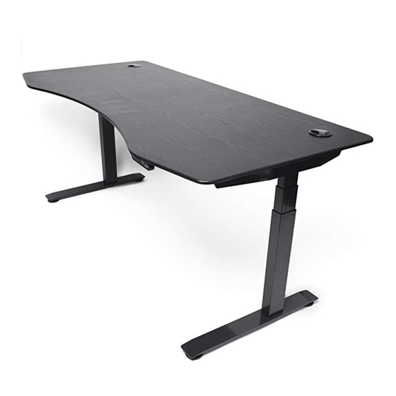
ApexDesk Elite Series Assembly Manual
Electric height-adjusted sit to stand desk
Hide thumbs
Also See for Elite Series:
- Assembly manual (11 pages) ,
- Assembly manual (12 pages) ,
- Assembly manual (20 pages)
Advertisement
Advertisement

Summary of Contents for ApexDesk Elite Series
- Page 1 ELECTRIC HEIGHT-ADJUSTED SIT TO STAND DESK Elite Series Assembly Guide 8/12/2017...
-
Page 2: Table Of Contents
CAUTION, USE & LIABILITY .......................... 3 PARTS & HARDWARE LIST ........................... 4 PARTS / COMPONENT DIAGRAMS ......................5 ASSEMBLY INSTRUCTIONS ........................6 TROUBLESHOOTING ........................... 11 CABLE MANAGEMENT TRAY INSTALLATION ................. 113 WARRANTY INFORMATION ........................155 Elite Series Assembly Guide P a g e... -
Page 3: Caution, Use & Liability
The desk height is adjustable so that it can be positioned at the most suitable height. Any other use is at user’s risk. Under no circumstances does the manufacturer accept warranty claims or liability claims for damages caused from improper use or handling of the desk. Elite Series Assembly Guide P a g e... -
Page 4: Parts & Hardware List
Allen wrench 5mm x 1 HARDWARE INCLUDED 14PCS 4PCS 3PCS 4PCS φ8×135mm M6×16 M5×10 M6×16 HARDWARE LIST M6x16mm hexagon screw L-shaped locking lever M5x10mm hexagon screw M6x16mm hexagon screw ST4.8x7mm pan-head screw Elite Series Assembly Guide P a g e... -
Page 5: Parts / Component Diagrams
PARTS / COMPONENT DIAGRAMS PARTS / COMPONENT LIST Desk top Foot Lifting column Top support bracket Beam Control box Controller Elite Series Assembly Guide P a g e... -
Page 6: Assembly Instructions
Use 5mm Allen wrench to secure foot to column with four Screw A (M6x16mm) on each side. STEP 2 Use 4mm Allen wrench to secure top support bracket to beam with two Screw D (M6x16mm) on each side. Elite Series Assembly Guide P a g e... -
Page 7: Lifting Column
Each locking lever consists of axle (shorter end) and handle (longer end). Insert axle into the hole on the right side first, and then the hole on the left. Please make sure the handle is on your LEFT side when facing the lifting column. Elite Series Assembly Guide P a g e... - Page 8 If you want controller to be installed on the left hand, simply reverse the control box. Please note that two mounting holes for controller are only pre-drilled on the right-hand side not on the left-hand side of the desk top. Elite Series Assembly Guide P a g e...
- Page 9 The buttons are not designed to be super-sensitive. You will need to press HARD in the center of the buttons. Your desk is ready to use once this process is completed. Elite Series Assembly Guide P a g e...
- Page 10 Screw A (M6x16mm). Use a Philips screwdriver to secure controller to the pre-drilled holes on the bottom of the top with two Screw E (ST4.8x7mm). Adjust leveling studs on the feet. Make sure the stubs make solid contact with the floor. Elite Series Assembly Guide 10 | P a g e...
-
Page 11: Troubleshooting
UP and DOWN arrow buttons for 3 seconds, and then release both buttons. The desk will first go to the lowest position, then the highest position and finally stops in between. Elite Series Assembly Guide 11 | P a g e... - Page 12 Reset desk. If problem persists, switch motor cables at control box or replace controller and attempt another reset. Height record error. Unplug power and re-plug after 10 seconds. Reset desk. Overheat. Stop using desk for 10 minutes and let it cool down. Elite Series Assembly Guide 12 | P a g e...
- Page 13 INSTALLING CABLE MANAGEMENT TRAY (SOLD SEPARATELY) Step 1: Locate two screw holes on the backside of the beam and mount the tray as illustrated below with two wing screws and washers Elite Series Assembly Guide 13 | P a g e...
- Page 14 Step 2: If adjustment is needed, loosen the screws below, slide the tray to the left or right and tighten the screws. Step 3: Insert two cable clamps Elite Series Assembly Guide 14 | P a g e...
-
Page 15: Warranty Information
ApexDesk’s obligation under this warranty is limited to the repair or replacement, at ApexDesk’s sole option, of the parts or products the defect of which are reported to ApexDesk within the applicable warranty period and which, upon examination by ApexDesk, prove to be defective.


Need help?
Do you have a question about the Elite Series and is the answer not in the manual?
Questions and answers