
Related Manuals for Mira Vier


Summary of Contents for Mira Vier
- Page 1 Mira Vier These instructions must be left with the user Installation Guide 1144486-W2-K...
-
Page 2: Table Of Contents
If you experience any difficulty with the installation or operation of your new shower, then please refer to the Fault Diagnosis section, before contacting Kohler Mira Ltd. Our telephone and fax numbers can be found in the back of this guide. -
Page 3: Introduction
Having done so, keep it handy for future reference. The Mira Vier Mixer Valve is designed to be used with the Mira Vier showerhead and fittings. Products Covered by this Guide Mira Vier Digital Mixer - High Pressure/Combi Valve Mira Vier Digital Mixer - Pumped Valve. -
Page 4: Important Safety Information
1. THIS APPLIANCE MUST BE EARTHED. ENSURE SUPPLEMENTARY BONDING COMPLIES WITH THE “REQUIREMENTS FOR ELECTRICAL INSTALLATIONS”. The Mira Digital Mixer Valve is intended to be permanently connected to the fixed electrical wiring of the mains system. A means for electrical isolation of the appliance shall be provided in the fixed wiring in accordance with local wiring regulations. - Page 5 Caution! 1. Read all of these instructions and retain this guide for later use. 2. The electrical installation must comply to “BS 7671 - Requirements for Electrical Installations” commonly referred to as the IEE Wiring Regulations, or any particular regulations and practices, specified by the local electricity supply company.
-
Page 6: Pack Contents
PACK CONTENTS Tick the appropriate boxes to familiarise yourself with the part names and to confirm that the parts are included. Documentation 1 x Wireless Controller User Guide 1 x Showerhead User Guide 1 x Customer Support Brochure Digital Mixer Valve Digital Mixer - Digital Mixer - Pumped Valve High Pressure/Combi Valve... - Page 7 Ceiling Fed Fittings 1 x Plastic Pipe 1 x Ceiling Plate 2 x Spacers 1 x Showerhead 1 x Elbow Kit 1 x Extension 2 x Brackets 1 x Slide Bar Assembly 2 x Hex Screws 1 x Hose 2 x Wall Plugs 2 x Rubber Washers 2 x 45mm Screws 2 x 70mm Screws...
- Page 8 Rear Fed Fittings 2 x End Plugs 2 x Brackets 1 x Showerhead 1 x Hose 1 x Slide Bar Assembly 2 x Rubber Washers 1 x Right Angle Connector (RAC) Kit 1 x Right Angle Connector Shroud 2 x Hex Screws 2 x Wall Plugs 2 x 45mm Screws 1 x Installation Template...
-
Page 9: Specifications
SPECIFICATIONS Standards and Approvals The Mira Vier complies with all relevant directives for CE marking. The Mira Vier is a type 1 electronic, independently mounted control for surface mounting. The Mira Vier is in compliance with the essential requirements of the R&TTE directive 1999/5/EC. - Page 10 Mira Digital Mixer Valve Pumped Pressures Maximum Static Pressure 100 kPa (1 bar) = 10 m max. total head Maximum Maintained Pressure 100 kPa (1 bar) = 10 m max. total head Minimum Maintained Pressure 1 kPa (0.01 bar) = 0.1 m min. total head...
-
Page 11: Dimensions
MIN. SUPPLY PRESSURE: 50 kPa (0.5 bar) MAX. WORKING PRESSURE: 500 kPa (5 bar) MAX. STATIC PRESSURE: 1000 kPa (10 bar) (WRAS) MAX. SUPPLY WATER TEMP: 65 °C MOUNTING POSITION VERTICAL HORIZONTAL KOHLER MIRA LTD. CHELTENHAM GL52 5EP TEL: (+44) 0870 241 0888 www.mirashowers.co.uk COLD F8624... -
Page 12: Installation
• Interference from other radio signals can dramatically reduce the ability of the Vier Wireless Controller / digital mixer to register or communicate. This may include; mobile phones, radio control boiler thermostats, wireless broadband routers, radio control toys, cordless phones, remote outdoor weather stations, wireless doorbells etc. - Page 13 Typical Suitable Installations: 1. Instantaneous Multipoint Water Heaters and Combination Boilers Caution! Risk of product damage. Do not fit the Mira Digital Mixer - PUMPED VALVE with Instantaneous Multipoint Water Heaters or Combination Boilers. Combination Boiler Key to Symbols warm...
- Page 14 The Mira Dual outlet digital mixing valves do not have a factory fitted hot inlet flow regulator. These are supplied in the component pack. The table indicates which flow regulator should be fitted in the hot water inlet of the Mira Digital Mixer Valve if installing to a combination boiler system.
- Page 15 2. Mains Pressurised Instantaneous Hot Water Shower, Heated from a Thermal Store Caution! Risk of product damage. Do not fit the Mira Digital Mixer - PUMPED VALVE with Mains Pressurised Systems. Digital Mixer...
- Page 16 3. Gravity Fed Showers Caution! Risk of product damage. Do not fit the Mira Digital Mixer - HIGH PRESSURE/COMBI VALVE with Gravity Fed Systems. 100 mm from the lowest level of water in the tank Cistern Digital Mixer Minimum 230 litres...
- Page 17 Typical Examples of Poor Plumbing and Installation Practices DO NOT: • Install the Digital Mixer Valve where it can become frozen • Install the Digital Mixer Valve where it can be subjected to ambient tempera- tures in excess of 40ºC •...
-
Page 18: Installation Schematic
3 amp switched fused spur. Easily Accessible Mira Vier Shower Fittings & Wireless Controller A separate, permanently connected supply must be taken from the ring main to the appliance through a 3 amp double pole switched fuse spur providing a minimum 3mm contact separation gap in each pole. - Page 19 Long inlet pipework (dead-legs) should be kept to a minimum to avoid temperature fluctuations. Supply pipework layout must be arranged to minimize the effect of other outlet usage upon the dynamic pressures at the Digital Mixer Valve inlets. To eliminate pipe debris it is essential that supply pipes are thoroughly flushed through before connection to the Digital Mixer Valve.
-
Page 20: Position And Signal Test
Digital Mixer Valve Position and Signal Test ISOLATE MAINS ELECTRICITY BEFORE REMOVING COVER! DIGITAL MIXER 2 WIRELESS MIRA DM2 WIRELESS HP/COMBI 1666.009 N85A MANUFACTURED POWER: 230 V AC 20 W PROTECTION: IP24 MIN. SUPPLY PRESSURE: 50 kPa (0.5 bar) MAX. WORKING PRESSURE: 500 kPa (5 bar) MAX. - Page 21 The ambient temperature of Digital Mixer Valve site (loft space, airing cupboard etc...) can have an effect on showering temperature. Insulate all pipework as required, particularly from the Digital Mixer Valve to the Shower Fitting. The temperature indicated on the wireless controller display is measured inside the digital mixing valve and due to site conditions is not necessarily the temperature delivered at the shower outlet.
- Page 22 Drill and plug the fixing holes. Note! Installers may wish to use alternative cavity fixings, when installing onto a dry lined, stud partition, shower cubicle or laminated panel wall structures. However, these methods of fixing are beyond the scope of this guide. Secure the Digital Mixer Valve in position with the fixing screws (supplied).
-
Page 23: Shower Fittings - Ceiling Fed
Shower Fittings - Ceiling Fed Suitable for solid, dry-lined, stud partition, shower cubicle or laminated panel walls. The Slide Bar should be fixed to the wall at a convenient height for all the family. It should be positioned so that water sprays down the centre of the bath, or away from the opening of a shower cubicle. - Page 24 Drill and plug Slide Bar Assembly fixing holes. Insert fixing screws through holes in Wall Brackets and fix to wall. Do not fully tighten. Use template to set correct distances between Wall Brackets. Fully tighten screws. Use longer fixing screws if using spacers supplied.
- Page 25 Fit Slide Bar Assembly over Wall Brackets and secure with screws supplied. (Do not overtighten.) Connect ceiling extension tube. Feed plastic pipe up through the slide bar and extension into ceiling. Do not allow any debris to block the plastic pipe. Note! If plastic pipe requires shortening, make sure there is enough length to fit elbow (supplied) or alternative push-...
-
Page 26: Shower Fittings - Rear Fed
Place first washer in end of hose, then attach to pipe end. Do not fit showerhead until after pipework has been fully flushed through. See section “Commissioning”. Shower Fittings - Rear Fed Suitable for solid, dry-lined, stud partition, shower cubicle or laminated panel walls. The Slide Bar should be fixed to the wall at a convenient height for all the family. - Page 27 Insert fixing screws through holes in Wall Brackets and fix to wall. Do not fully tighten at this stage. Use template to set correct distances between Wall Brackets. Fully tighten screws. Note! Slots in Wall Brackets allow for adjustment. Use one horizontal slot and one vertical slot.
- Page 28 The pipe work must protrude through the wall between 20 - 23 mm from the finished surface of the wall. If the pipe protrudes further than 23 mm, it will prevent the backplate nut from engaging with the backplate. If necessary cut the pipe to the correct length and remove any burrs.
- Page 29 Place the backplate over the outlet Backplate pipe with the arrow pointing vertically up and tighten the two backplate screws. Make sure that the foam seal Copper Pipe abuts the finished wall surface. Fit the olive and the backplate nut over the outlet pipe, do not tighten the nut 2 x Screws fully at this point.
-
Page 30: Wireless Controller
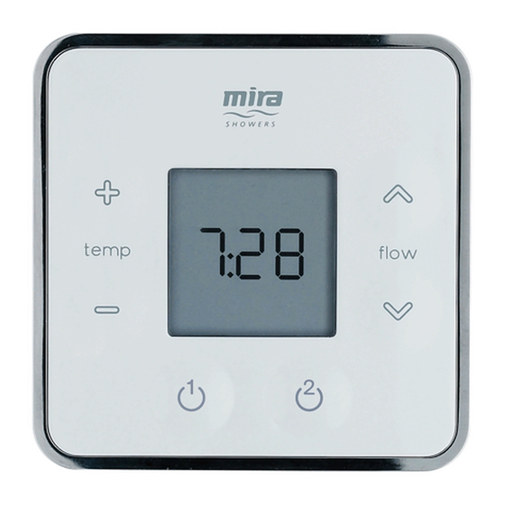
Wireless Controller Suitable for solid, dry-lined, stud partition, shower cubicle or laminated panel walls. The Wireless Controller should be fixed to the wall at a convenient height for all the family. It should be positioned so that water does not spray over it when the Showerhead is held on the Slide Bar. -
Page 31: Commissioning
COMMISSIONING Turn on electrical supply to Digital Mixer Valve. Make sure the end of the hose is in either the bath, shower tray or other water catchment area. Press “ ” button and reduce temperature to full cold “CLd”. Press “... - Page 32 Run cold water through (approximately 2 minutes) and check entire installation for water leaks. Press “ ” to turn shower off. Fit the second hose washer and showerhead. Press “ ” to turn shower on. Test operation of shower by increasing/decreasing both temperature and flow controls.
-
Page 33: Connecting A Second Wireless Controller
CONNECTING A SECOND WIRELESS CONTROLLER The following procedure details how to assign the Wireless Controller to the Digital Mixer Valve and test the remote signal strength. Note! Other radio signals from sources such as mobile phones, radio controlled boiler thermostats, wireless broadband etc. can dramatically reduce the ability of the digital mixer valve to register. -
Page 34: Re-Registering
RE-REGISTERING The wireless controller has previously been registered to the digital mixer at the factory, if communication problems are encountered, a re-registering of the wireless controller may be required. A re-registering of the wireless controller must also be performed should the control PCB in the Digital Mixer Valve be replaced. -
Page 35: Fault Diagnosis
“Position and Signal Test” Wireless controller lost Re-register the wireless controller, refer to “Re- registration. Registering”. Digital Mixer valve box or Contact Kohler Mira Ltd. Wireless Controller failure 1144486-W2-K... - Page 36 Batteries” in the Wireless fitted. Controller User Guide. Wireless controller failure. Contact Kohler Mira Ltd. No water flow / will not turn on HP/Combi valve fitted to a HP/Combi valves are not suitable Pumped Gravity water system...
- Page 37 “Typical Suitable Installations” No product fault. Appliance not suitable for negative Digital Mixer valve box installed head installation, refer to above cold water storage cistern “Installation” (Pumped valve only) Contact Kohler Mira Ltd Digital Mixer valve box failure 1144486-W2-K...
- Page 38 “Typical Suitable Installations” Contact Kohler Mira Ltd Digital Mixer valve box or Wireless Controller failure Refer to “Loss of / or poor radio Temperature and flow control Loss of / or poor radio...
- Page 39 Refer to “Use of Flow and out (HP/Combi valve only) Regulators” for correct operation Outlet pipe run is too long Ensure outlet pipe work is thermally lagged. Digital Mixer valve box or Contact Kohler Mira Ltd Wireless Controller failure 1144486-W2-K...
- Page 40 Disable the ‘warm-up’ feature, used with a combi boiler (HP/ refer to ‘Changing Functions’ Combi valve only) refer to ‘Use in the Wireless Controller User of Warm-up’ Guide Digital Mixer valve box or Contact Kohler Mira Ltd Wireless Controller failure 1144486-W2-K...
- Page 41 “Typical Suitable Installations” Reversed inlet supplies Check and remedy Digital Mixer valve box failure Contact Kohler Mira Ltd Internal Leaking Pumped Gravity LP valve Pumped Gravity LP valves fitted to a HP/Combi water are not suitable for connection...
- Page 42 Refer to “Loss of / or poor radio communications” communications (out of range symbol maybe illuminated on section above wireless controller). Contact Kohler Mira Ltd Digital Mixer valve box failure Noise Digital Mixing valve air locking Check for correct installation practices, repeat...
-
Page 43: Maintenance
MAINTENANCE General Read the section “Important Safety Information” first. Before replacing any parts ensure that the underlying cause of the malfunction has been resolved. If the shower is dismantled during installation or servicing then upon completion the product must be inspected to ensure there are no leaks. Warning! There are no user serviceable components beneath the cover of the appliance. -
Page 44: Spare Parts
SPARE PARTS Digital Mixer - High Pressure/Combi Valve 1742.062 1742.060 Wall Plate Wireless Controller (x 7) 1666.223 Aerial 1742.061 Battery Cover 1666.191 Control PCB 1666.189 1666.210 Mixing Valve Assembly Thermistor Includes: 1666.199 (x3) 1666.209 (x2) 1666.210 (x1) 1666.209 1666.211 Inlet Cartridge Mains Cable + Filter (x1) 1666.199... - Page 45 Digital Mixer - Pumped Valve (x 7) 1666.221 Mains Cable 1666.224 Aerial 1666.192 Mixing Valve 1666.193 Assembly 1666.210 Control PCB Includes: Thermistor 1666.119 (x3) 1666.209 (x2) 1666.194 1666.210 (x1) Transfer Tube A, C 1666.209 Inlet Cartridge + Filter (x1) 1666.198 Outlet Tube 1666.196 1666.199...
- Page 46 Shower Fittings 1799.015 1688.194 Ceiling Plate Chrome 1688.195 Supply Tube Supply Tube 1688.205 360M Showerhead 1688.162 1688.191 Storm Assembly Upper Support 1688.166 Burst Assembly 1688.187 Slide Bar Support 1688.196 Pipe 1688.164 Connection 1688.185 1688.193 Cloud Pack Clamp Assembly Slide Bar Bracket 1688.160 Rain Assembly...
-
Page 47: Disposal And Recycling
DISPOSAL AND RECYCLING End of Product Life When this appliance has reached the end of its serviceable life, it should be disposed of in a safe manner, in accordance with current local authority recycling, or waste disposal policy. Batteries Spent batteries should not be disposed of with normal household waste. Contact your local authority for information on waste disposal and recycling. -
Page 48: Customer Service
Servicing must only be undertaken by us or our Spares and Accessories appointed representative. We hold the largest stocks of genuine Mira Note! If a service visit is required the product must spares and accessories.Contact us for a be fully installed and connected to services.
Need help?
Do you have a question about the Vier and is the answer not in the manual?
Questions and answers