
Related Manuals for Mira Vier


Summary of Contents for Mira Vier
- Page 1 Mira Vier Wireless Controller These instructions must be left with the user User Guide...
- Page 2 CONTENTS Introduction ..................... 3 General ....................3 Guarantee .................... 3 Safety Information ................... 3 Control Layout ..................4 Display Symbols ..................5 Using the Shower ..................6 Switch On ..................... 6 Adjust Temperature ................7 Adjust Flow ................... 7 Switch Off ..................... 8 Functions ....................
-
Page 3: Introduction
INTRODUCTION General Thank you for purchasing a quality Mira product. To enjoy the full potential of your new product, please take the time to read this guide thoroughly and keep it handy for future reference. The Mira Vier Wireless Controller is a remote user interface and controls the following functions: •... -
Page 4: Control Layout
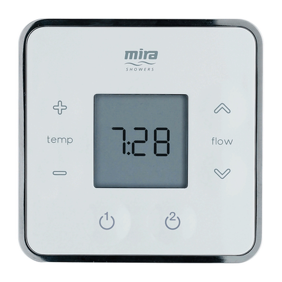
CONTROL LAYOUT Increase Increase Flow Temperature Decrease Temperature Decrease Flow Start/Stop Display... -
Page 5: Display Symbols
DISPLAY SYMBOLS Low Battery Eco Mode Display Temperature Flow Rate Control Out Of Range 12hr Clock... -
Page 6: Using The Shower
USING THE SHOWER Switch On Press “ ” to start shower. Temperature and flow settings will be same as when last used. After a short period, display will dim to help extend battery life. Shower will not run continuously for more than 30 minutes before stopping automatically (5 minutes when “ECO”... -
Page 7: Adjust Temperature
Adjust Temperature Adjust Temperature The temperature shown on the display is in degree Celsius (°C) and indicates the user requested temperature. Note: This temperature is measured inside the mixing valve and therefore will differ from that actually being delivered at the outlet. The amount the temperature differs by will depend on site conditions, ambient room temperatures and length of outlet pipe runs. -
Page 8: Switch Off
Switch Off Press “ ” to stop shower. After the shower has stopped, the display will turn off automatically. Note: It is normal for all shower outlets to continue to expel water for a short period of time after use. It is not uncommon for larger deluge shower heads, particularly those connected to long outlet pipe runs and therefore holding large volumes of water, to drain down water several hours after use due to the changes in the ambient temperature. -
Page 9: Functions
FUNCTIONS The following functions can be altered individually to adjust how the shower operates: Maximum Water Temperature. Factory Default: 45°C. This is the temperature the shower cannot go beyond when in use. ( U s e r A d j u s t a b l e Note: This temperature is measured inside the mixing Range between valve and therefore will differ from that actually being... -
Page 10: Function Menu
FUNCTION MENU To change any function, enter the function menu. Press “+” “ ” buttons simultaneously and hold until “End” appears. Note: This may take several seconds. Use “ ” or “ ” buttons to cycle through functions and press “ ” to enter setting. (See following sections in this guide for details on each function and how to alter their settings.) Note! If signal... -
Page 11: Changing Functions/Settings
CHANGING FUNCTIONS/SETTINGS F1 - Maximum Water Temperature Factory default “45°C”. This is the temperature the shower cannot go beyond when in use. This temperature is measured inside the mixing valve and therefore will differ from that actually being delivered at the outlet. The amount the temperature differs by will depend on site conditions, ambient room temperatures and length of outlet pipe runs. - Page 12 Press “ ” to set. Press “ ” to exit back to Function Menu. Cycle menu to “End” and press “ ” to exit the Function Menu.
- Page 13 F2 - Eco Factory default “off”. Switching Eco “on” will limit the showering duration to 5 minutes and also reduce the achievable flow rate. The flow display cannot be altered past half its maximum position on the display and the word “Eco” symbol will be permanently illuminated. Enter the Function Menu.
- Page 14 Press “ ” to set. Press “ ” to exit back to Function Menu. Cycle menu to “End” and press “ ” to exit the Function Menu.
-
Page 15: F3 - Warm-Up
F3 - Warm-Up Factory default “off”. Note: Not recomended for use with Combination Boilers. Switching Warm-Up “on” allows the shower to warm-up or flush through any cold water dead legs in your water system prior to showering. After pressing the on/ off button there will be a 5 second delay before water is flushed through. - Page 16 Press “ ” to set. Press “ ” to exit back to Function Menu.
-
Page 17: F4 - Clock Setting
F4 - Clock Setting Factory default “10:00” (4:00 unregistered, see “Connecting a Second Wireless Controller” when the batteries are connected) Note: The clock is 12hr and does not indicate am or pm. Enter the Function Menu. Cycle menu to “F 4” and press “ ”. Press “... -
Page 18: F5 - Clock Display
F5 - Clock Display Factory default “on”. Note: Leaving the clock display switched “on” allows the clock to be seen briefly after any temperature or flow rate user alteration. Enter the Function Menu. Cycle menu to “F 5” and press “ ”. Press “... - Page 19 Press “ ” to set. Press “ ” to exit back to Function Menu. Cycle menu to “End” and press “ ” to exit the Function Menu.
-
Page 20: F6 - Flow Range
F6 - Flow Range For use with High Pressure/Combi valve only. Factory default “1 - 99”. Allows the water flow rate to be adjusted to within desired range. Note: This function is only to be used during maintenance and commissioning. Accidental use may result in poor flow rate being set. - Page 21 Water begins to flow and the lower limit is displayed, e.g. “L 1”. Adjust flow to desired lower limit using “ ” & “ ”. Note! If hot water is supplied from a combination boiler, make sure the lower limit is sufficient to activate the boiler.
- Page 22 Press “ ” to set higher limit. Water flow stops. Press “ ” to set and exit back to Function Menu. Cycle menu to “End” and press “ ” to exit the Function Menu.
-
Page 23: F7 - Control Frequency
F7 - Control Frequency Factory default “1”. Note: Allows you to alter the Control Frequency setting if you are experiencing unreliable radio communications such as the shower cutting out or poor temperature and flow control response. For more information on unreliable radio communications refer to the “Fault Diagnosis”... - Page 24 Press “ ” to set. Press “ ” to exit back to Function Menu. Cycle menu to “End” and press “ ” to exit the Function Menu.
-
Page 25: Replacing The Batteries
REPLACING THE BATTERIES Change the batteries when the low battery symbol is displayed. To access the batteries, the controller must be removed from the wall. Press button to release and remove the controller from the wall. Make sure the controller is dry before removing the battery cover. -
Page 26: Fault Diagnosis
FAULT DIAGNOSIS Error Codes A specific problem relating to the electronic function of the shower will result in an error code being displayed on the control. The display will briefly flash “Err” followed by error code number and the shower will safely turn off. As with most electronic equipment resetting the mixing valve by powering it down at the mains, waiting a few seconds and powering it up again can often cure any issues. - Page 27 3. Run the shower for a few minutes. If the Error Code returns, make a note of the error code and contact our Customer Services Team. For more information see the Installation Guide Fault Diagnosis Section. Control Sensor or PCB Relay Error (E36) 1.
- Page 28 2. Run the shower for a few minutes. If the Error Code returns, replace the Digital Mixer Main Control PCB. (To be performed by competent tradesperson only!) 3. Run the shower for a few minutes. If the Error Code returns, make a note of the error code and contact our Customer Services Team.
-
Page 29: Connecting A Second Wireless Controller
CONNECTING A SECOND WIRELESS CONTROLLER The following procedure details how to assign the Wireless Controller to the Digital Mixer Valve and test the remote signal strength. Note! Other radio signals from sources such as mobile phones, radio controlled boiler thermostats, wireless broadband etc. can dramatically reduce the ability of the digital mixer valve to register. -
Page 30: Re-Registering
Place wireless controller in approximate final position (no more than 10 m (free air) from digital mixer valve) and test wireless signal by pressing “ ”, and adjusting the temperature. If temperature display remains unchanged and “out of range” symbol is Out of Range displayed, units are unable to communicate with each other. -
Page 31: Cleaning
CLEANING Many household cleaners contain abrasives and chemical substances, and should not be used for cleaning chrome plated or plastic parts. These finishes should be cleaned with a mild washing up detergent or soap solution, and then wiped dry using a soft cloth. DISPOSAL AND RECYCLING End of Product Life Electrical and electronic devices contain a range of materials that can be separated... -
Page 32: Customer Service
Servicing must only be undertaken by us or our Spares and Accessories appointed representative. We hold the largest stocks of genuine Mira Note! If a service visit is required the product must spares and accessories.Contact us for a be fully installed and connected to services.
Need help?
Do you have a question about the Vier and is the answer not in the manual?
Questions and answers
only one shower head working. The overhead shower - Number 2 on the control panel has stopped working