Table of Contents
Advertisement
Quick Links
Thank you for purchasing our product. Before installing/operating the product, read the instructions carefully and retain them
for future reference.
Attention!
● For installation, follow the steps described. Any damage caused by wrong installation shall be imputed to the users.
● To avoid a short circuit from occuring do not pull or modify the wires during installation.
● Do not disassemble or change any parts. Opening and dissassembling this unit will void any warranty.
● Maintenance and repairs should be executed by our professionals only.
Symbol description:
NOTE
Some procedures must be followed to avoid damages to the instrument.
WARNING!
Certain procedures must be followed to avoid damages to yourself, to the vehicle or to others.
1-1
Accessories
1
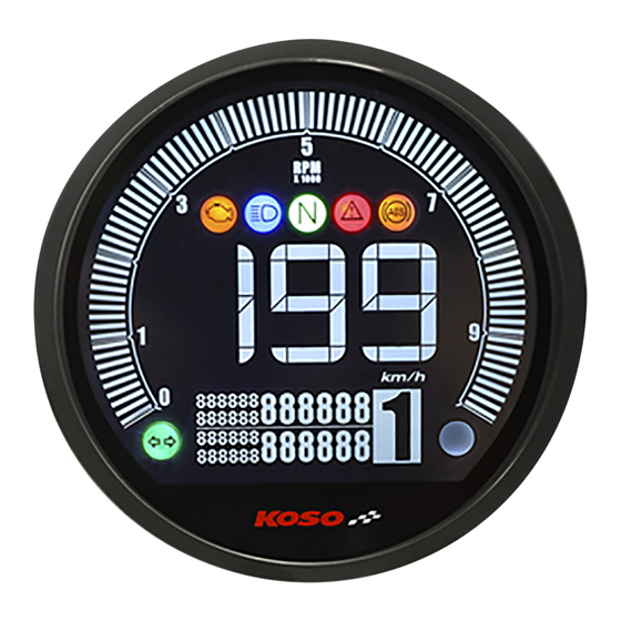
LCD Meter X1
5
RPM wire set
(TYPE B) X1
9
Rubber strip X1
13
2.5 mm Allen key X 1
17
M5x16L mm Screw X1
21
M8 x 30L Allen screw X2
25
M8 Bushing X2
2
Main wiring harness X1
6
Extension wire X1
10
M8 / S type speed
sensor bracket X 1
14
3 mm Allen key X1
18
M5x12L mm Screw X2
22
M6 Bushing X2
3
Active speed sensor X1
7
Temperature sensor X1
M10 / S type speed
11
sensor bracket X 1
15
Meter bracket X1
19
M5 washer X3
23
M8 Bushing X2
Flash
Light on
Hold the
Hold the
Button
Button
1 second
3 seconds
4
RPM wire (Type A) X1
8
External switch
(Dual button type) X1
M5x5xP0.8
12
Hexagon screw X 2
16
Bracket sleeve X1
20
M6 x 35L Allen screw X2
24
M6 Bushing X2
wh077ba07a(P15-1)
Advertisement
Table of Contents

Subscribe to Our Youtube Channel
Related Manuals for Koso DL-04


Summary of Contents for Koso DL-04
- Page 1 Thank you for purchasing our product. Before installing/operating the product, read the instructions carefully and retain them for future reference. Attention! ● For installation, follow the steps described. Any damage caused by wrong installation shall be imputed to the users. ●...
-
Page 2: Optinal Accessories
Optinal accessories L type speed sensor Water temp sensor Oil temp sensor adapter bracket adapter M12 X P1.5 X 15L M14 X P1.25 X 15L M14 X P1.5 X 15L M16 X P1.5 X 15L M18 X P1.5 X 15L M16. -
Page 3: Installation Instructions
Installation instructions Follow the steps below during installation. 1. M6 or M8 Allen screw X2 (Accessory20,21) 2. M6 or M8 Bushing X2 (Accessory22,23) 3. Meter bracket (Accessory15) 4. M6 or M8 Bushing X2 (Accessory24,25) 5. Handle bar bracket NOTE You can also install it (meter bracket) on the original meter bracket. -
Page 4: Meter Size
The active speed sensor could be facing the metal parts to detect the speed. EX. 1 The disc screw. EX. 2 The disc to detect the disc gap. (Make sure the distances between the gaps are the same in advance to avoid wrong speed signal.) EX. -
Page 5: Specifications
Specifications ●Speedometer ○ Overheat warning Display range : 0 ~ 360 km/h (0 ~ 225 MPH) Setting range : 60~250 °C(140~482 °F), When setting Display unit : 1 km/h (MPH) Switchable exceeding the set warning value, the value flickers, ○ Speeding warning Setting range : 30~360 km/h (19~225 MPH),When and the warning signal will be lit according to the setting. - Page 6 Main Menu Switching Description (including the warning screen)-Up button ●In the total mileage screen, press the Up button ●In the TRIP O screen, press the button to enter the TRIP A screen. to enter the Max. record screen. ●In the total mileage screen, press the Up button ●Press the button for 8 seconds for 3 seconds to enter the setting screen.
- Page 7 Setting Screen Switching Description ●Press the Up button for 3 seconds on the main screen(ODO) to switch to the setting screen. ●Press the Up button or Down button to select ❶Clock ❷Unit(Speed/Temperature) ❸Backlight(Brightness) ❹Tire circumference,Sensor point ❺Gear ❻RPM input pulse, Signal impulse,RPM range ❼Fuel resistance ❽Speeding warning ❾Shift light warning ❿Overheat warning ⓫Fuel warning ⓬Voltage warning⓭Motor oil maintenance ⓮Warning light warning ⓯ABS warning ⓰Internal and External ODO ⓱Exit NOTE...
-
Page 8: Clock Setting
Clock Setting ●Press the Down button to move to the ●The Clock screen, press the Down digit you want to set. button for 3 seconds to enter the ●Example : To set clock(minute) as Clock setting. 10 minutes. Now the setting value is flashing. -
Page 9: Backlight(Brightness) Setting
Backlight(Brightness) Setting ●EX : The backlight brightness setting is ●The backlight screen, press the Down changed from 3/5 (60%) to 2/5 (40%). button for 3 seconds to enter the ●Press the Down button to go back to backlight setting. the backlight screen. ●Example : To set the backlight ●The backlight screen... - Page 10 Gear Setting ●The gear screen, press the Down button for 3 seconds to enter the gear setting. P .S. ●During actual gear level learning, select road that is wide and has more straight distance with no traffic lights for more accurate settings and traffic safety.
- Page 11 ●The RPM input pulse & signal impulse ●Example : To set RPM range to & RPM range screen. 15,000 RPM. ●Press the Up button to choose the setting options. Now the setting value is flashing. NOTE Setting range : 10,000RPM/ 15,000 RPM.
- Page 12 5-7-1 油量表阻抗值(Ω)操作設定 5-7-3 Fuel Gauge Resistance Setting (Auto Detection) ●Press the Down button to enter the fuel gauge resistance setting(auto detection). The highest position CAUTION! ●If the fuel surface sensor float in the ●Before detection, ensure that your highest position then press the Up current fuel level is in the lowest position button, it will detect the resistance that you would like to have.
- Page 13 5-10 Overheat Warning Setting ●EX : Set overheat warning value from ●The overheat warning screen, press the 90 ˚C to 120 ˚C. Down button for 3 seconds to enter the overheat warning setting. ●Press the Down button to go back to the overheat warning setting.
- Page 14 ●Example : To set mileage maintenance ●EX : The motor oil maintenance setting value to 12,000. is changed from 500 km to 12,000 km. ●Press the Down button to move to ●Press the Down button to go back to the digit you want to set. the motor oil maintenance screen.
-
Page 15: Exit Setting
5-16 Internal and External ODO Setting ●Press the Up button to choose ●The internal and external ODO screen, the setting number. press the Down button for 3 seconds to enter the external ODO setting. User unable to adjust or clear internal ODO.
Need help?
Do you have a question about the DL-04 and is the answer not in the manual?
Questions and answers