Table of Contents
Advertisement
Quick Links
Download this manual
See also:
User Manual
WHAT'S IN THE BOX
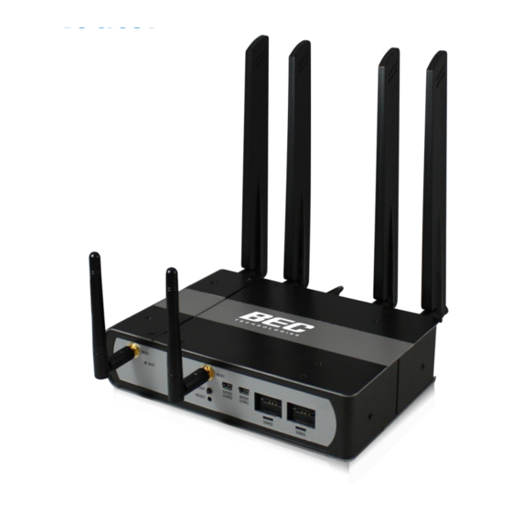
1 x BEC MX-1000 M2M Router
1 x This Quick Install Guide
1 x CD containing the User Manual
1 x Mounting Bracket
1 x MiniFIT to DC Jack Power Cable
2 x Wi-Fi Antennas
5 x Red Dust Caps
1
Insert the SIM Card
Note: Power o the MX-1000 before inserting/removing the SIM
Remove the SIM cover
WIFI
WIFI
then insert the SIM card(s)
WIFI
WIFI
WIFI
(2FF) with the mental
MINI
WIFI
WIFI ON/OFF
USB2
MINI
contacts (gold plate) facing
WIFI ON/OFF
USB2
RESET
RESET
up to the SIM slot(s) then
push it all the way in until
you hear the clicking sound. Replace the metal SIM cover
after inserting the SIMs.
2
Attach the Wi-Fi Antennas
Note: Use the plastic red caps to cover unused antenna ports
Screw the 2 female
RP-SMA Wi-Fi antennas
until fully attached to the
Wi-Fi ports on MX-1000.
Do not over-torque the
antenna on the connector.
3
Attach the LTE & GPS Antennas
Note: Use the plastic red caps to cover unused antenna ports
Screw the 2 male SMA
Cellular/or GPS antennas
until fully attached to the
Cellular and/or GPS
WAN1
WAN1
modules.
MAIN
MAIN
Connect to the MAIN port,
the primary cellular antenna
port to transmit and
receive signal, if decide to
use one LTE antenna.
Do not over-torque the antenna on the connector.
4
Connect to Mini USB Ports
Note: Need to install a special driver before connecting the device
Connect to Mini USB port(s)
for direct connection to the
Cellular module(s) for
management – debug,
change firmware, and
configuration.
(Optional Accessories)
DC Power Adapter
3G/4G Antennas
Active GPS Antenna
Vehicle Power Cable
Ethernet (RJ-45) Cable
SETTING UP THE ROUTER
MINI
USB1
MINI
USB1
SIM2
SIM1
SIM2
SIM1
WAN1
WAN1
WIFI
WIFI
MAIN
MAIN
WIFI
WIFI
WIFI ON/OFF
RESET
WAN1
WAN1
WAN1
WAN1
WAN2
WAN2
WAN2
WAN1
WAN1
GPS
GPS
GPS
MAIN
MAIN
MAIN
MAIN
AUX
AUX
AUX
AUX
WAN1
WAN2
WAN1
GPS
MAIN
AUX
AUX
POWER
INTERNET
USB1
USB2
GPS
WAN1
POWER
1
2
Gb ETH
MINI
MINI
USB2
USB1
5
Connect to Power Source
Use the DC Power Adapter
Attach the 4-pin MiniFIT to
DC Jack Power Cable to the
MX-1000 then plug in the
DC power adapter,
15VDC 1.6A.
Use Vehicle Electrical System (Power & Ignition Sensing)
Attach the Vehicle hardwire power
cable to the MX-1000 and connect
the wire leads of the power cable
WIFI
WIFI
to vehicle's electrical system.
WIFI
MINI
MINI
USB2
USB1
BLACK Wire (PIN 1 & 2):
SIM2
SIM1
Ground (GND). Use one
of the BLACK wires for
a neutral or ground
connection
WHITE Wire (PIN 3): ACC/ON for Ignition Input wire need to be
connecting into vehicle accessory wire.
RED Wire (PIN 4): VCC/OFF Voltage wire to the battery.
DC power range from 0V to 56V.
WAN1
WAN2
WAN2
WAN2
WAN2
WAN2
WAN2
AUX
AUX
MAIN
MAIN
MAIN
MAIN
MAIN
MAIN
WAN2
MAIN
WAN2
3
4
2
3
6
Access to the MX-1000
Access to the MX-1000 Web interface by entering
http://192.168.1.254 in the address bar of the web browser.
Default Login Information: Username (admin) and Password
(admin).
The Quick Start Wizard provides key steps to connect the
MX-1000 to the Internet.
Model: MX-1000
Quick Install Guide
POWER
GND
VCC
Battery
PIN
Definition
Details
1
1
Ground
2
Ground
4
3
ACC
Input
4
VCC
10~56VDC
M
M
2
POWER
Ignition Switch
ACC
Fuse
Wire color
-
Black
-
Black
White
Red
Advertisement
Table of Contents

Related Manuals for BEC MX-1000


Summary of Contents for BEC MX-1000
-
Page 1: Quick Install Guide
5 x Red Dust Caps SETTING UP THE ROUTER Connect to Power Source Insert the SIM Card Use the DC Power Adapter Note: Power o the MX-1000 before inserting/removing the SIM Remove the SIM cover Attach the 4-pin MiniFIT to WIFI WIFI... - Page 2 DEVICE OVERVIEW & LEDS SIM Card Slots Wi-Fi Female RP-SMA (Dual SIM Dual Module) Antenna Connector WIFI WIFI WIFI MINI MINI WIFI ON/OFF USB2 USB1 RESET SIM2 SIM1 Wi-Fi On/Off MINI USB & WPS Reset (LTE Module Management) GPS Antenna LTE #2 (Main Antenna) LTE #1 (Main Antenna) SMA Female Connector...
- Page 3 MOUNTING THE ROUTER MOUNTING BRACKET CONTAINS: Bracket plate and Ten (10) M4 Machine Screws The Bracket plate is designed to securely attach and mount the MX-1000 on any flat surface – including desktop, table, chassis, etc. Attach the fasten the Mounting Bracket (known as bracket...
Need help?
Do you have a question about the MX-1000 and is the answer not in the manual?
Questions and answers