Table of Contents
Advertisement
Quick Links
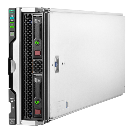
HPE Synergy 480 Gen10 Compute Module
Maintenance and Service Guide
Abstract
This document is for the person who installs, administers, and troubleshoots the HPE Synergy
system. Hewlett Packard Enterprise assumes you are qualified in the servicing of computer
equipment and trained in recognizing hazards in products with hazardous energy levels.
Part Number: 876832-003
Published: January 2018
Edition: 3
Advertisement
Table of Contents
Troubleshooting

Related Manuals for HPE Synergy 480 Gen10 series

Summary of Contents for HPE Synergy 480 Gen10 series
- Page 1 Maintenance and Service Guide Abstract This document is for the person who installs, administers, and troubleshoots the HPE Synergy system. Hewlett Packard Enterprise assumes you are qualified in the servicing of computer equipment and trained in recognizing hazards in products with hazardous energy levels.
- Page 2 © Copyright 2017, 2018 Hewlett Packard Enterprise Development LP Notices The information contained herein is subject to change without notice. The only warranties for Hewlett Packard Enterprise products and services are set forth in the express warranty statements accompanying such products and services.
-
Page 3: Table Of Contents
Compute module options........................11 M.2 SSD adapter board spare part..................11 M.2 flash drive spare parts..................... 12 HPE Trusted Platform Module 2.0 spare part.................12 HPE Smart Storage Battery spare part...................12 Mezzanine option spare parts....................12 HPE Synergy Internal SATA board spare part................12 Drive spare parts........................ - Page 4 HPE Synergy troubleshooting resources...................55 Troubleshooting within HPE OneView..................56 HPE Synergy Troubleshooting Guide..................56 Error Message Guide for HPE ProLiant Gen10 servers and HPE Synergy......56 HPE OneView Help and HPE OneView API Reference............56 HPE Synergy QuickSpecs...................... 56 HPE Synergy document overview (documentation map)...... 57 Component identification.................
- Page 5 NVDIMM LED identification....................71 NVDIMM-N LED combinations..................71 NVDIMM Function LED patterns..................71 Enterprise Midline USB......................72 LEDs............................72 Component and LED identification for HPE Synergy hardware............73 Cabling......................74 Cabling resources..........................74 HPE Smart Storage Battery cabling....................74 P416ie-m Smart Array Controller cabling..................74 Specifications....................
-
Page 6: Illustrated Parts Catalog
Illustrated parts catalog Mechanical components Hewlett Packard Enterprise continually improves and changes product parts. See the Hewlett Packard Enterprise PartSurfer website for complete and current supported parts information. Item Description Access panel spare part SFF HDD blank assembly spare part DIMM baffle spare parts Front panel/drive cage assembly spare parts Heatsink blank spare part... -
Page 7: Sff Hdd Blank Assembly Spare Part
Description Spare part number Front panel/drive cage assembly, standard 873079-001 Front panel/drive cage assembly, no drives 830892-001 HPE Synergy 480 Gen10 pull tab 873074-001 Rear heatsink blank spare part Customer self repair on page 17: mandatory Description Spare part number... -
Page 8: System Battery Spare Part
Description Spare part number 8-GB, 1Gx8, PC4-2666V-R 850879-001 16-GB, 2Gx4, PC4-2666V-R 850880-001 16-GB, 1Gx8, PC4-2666V-R 868846-001 32-GB, 2Gx4, PC4-2666V-L 850881-001 64-GB, 2Gx4, PC4-2666V-L 850882-001 HPE 16GB NVDIMM spare part Customer self repair on page 17: mandatory System battery spare part... -
Page 9: Processor Heatsink Spare Parts
Premium drive backplane 873076-001 Processor spare parts Customer self repair on page 17: no All Intel Xeon processors in this HPE ProLiant server must have the same cache size, speed, number of cores, and rated maximum power consumption. Description Spare part number... - Page 10 Description Spare part number Xeon-P 8180 28c 205W 875731-001 Xeon-P 8168 24c 205W 875730-001 Xeon-P 8164 26c 150W 875729-001 Xeon-P 8153 16c 120W 875728-001 Xeon-G 6154 18c 200W 875727-001 Xeon-G 6146 12c 165W 875726-001 Xeon-G 6144 8c 150W 875725-001 Xeon-G 6136 12c 875724-001 Xeon-G 6134 8c 130W 875723-001...
-
Page 11: Compute Module Options
Hewlett Packard Enterprise PartSurfer website. Item Description M.2 SSD flash drive and adapter board spare parts HPE Trusted Platform Module 2.0 spare part HPE Smart Storage Battery spare part Mezzanine option card (Type C) spare parts HPE Synergy Internal SATA board spare part Drive spare parts •... -
Page 12: M.2 Flash Drive Spare Parts
HPE Trusted Platform Module 2.0 spare part Customer self repair on page 17: no Description Spare part number HPE Trusted Platform Module 2.0 Gen 10 kit, TAA 872159-001 HPE Smart Storage Battery spare part Customer self repair on page 17: mandatory... -
Page 13: Drive Spare Parts
Description Spare part number HPE Synergy Internal SATA board 873085-001 Drive spare parts SFF SAS HDD spare parts Customer self repair on page 17: mandatory Description Spare part number 600 GB SAS 15,000-rpm, SFF SC DS HDD 870794-001 900 GB SAS 15,000-rpm, SFF SC DS HDD... -
Page 14: Sff Sata Hdd Spare Parts
SFF SATA HDD spare parts Customer self repair on page 17: mandatory Description Spare part number 1 TB SATA 7,200-rpm, SFF SC 512e DS HDD 765868-001 2 TB SATA 7,200-rpm, SFF SC 512e DS HDD 765869-001 1 TB SATA 7,200-rpm, SFF SC DS HDD 656108-001 SFF SAS SSD spare parts Customer self repair on page 17: mandatory... -
Page 15: Sff Nvme Ssd Spare Parts
Description Spare part number 400 GB SATA, 6G, WI, SFF SC DS SSD 872512-001 800 GB SATA, 6G, WI, SFF SC DS SSD 872514-001 1.6 TB SATA,, 6G, WI, SFF SC DS SSD 872516-001 240 GB SATA, 6G, RI, SFF SC DS SSD 868924-001 480 GB SATA, 6G, RI, SFF SC DS SSD 868936-001... -
Page 16: Usb And Microsd Option Spare Parts
SSD 340 GB 830453-001 USB and microSD option spare parts Customer self repair on page 17: mandatory Description Spare part number HPE Dual 8GB microSD EM USB device 799057-001 8-GB USB flash media key 743503-001 8-GB micro SDHC flash media card 738576-001... -
Page 17: Customer Self Repair
Customer self repair Hewlett Packard Enterprise products are designed with many Customer Self Repair (CSR) parts to minimize repair time and allow for greater flexibility in performing defective parts replacement. If during the diagnosis period Hewlett Packard Enterprise (or Hewlett Packard Enterprise service providers or service partners) identifies that the repair can be accomplished by the use of a CSR part, Hewlett Packard Enterprise will ship that part directly to you for replacement. - Page 18 Hewlett Packard Enterprise de remplacer ces pièces, l'intervention peut ou non vous être facturée, selon le type de garantie applicable à votre produit. REMARQUE: Certaines pièces Hewlett Packard Enterprise ne sont pas conçues pour permettre au client d'effectuer lui-même la réparation. Pour que la garantie puisse s'appliquer, Hewlett Packard Enterprise exige que le remplacement de la pièce soit effectué...
- Page 19 essere restituito con la documentazione associata nell'imballo di spedizione fornito. La mancata restituzione del componente può comportare la fatturazione del ricambio da parte di Hewlett Packard Enterprise. Nel caso di riparazione da parte del cliente, Hewlett Packard Enterprise sostiene tutte le spese di spedizione e resa e sceglie il corriere/vettore da utilizzare.
- Page 20 Parts-only Warranty Service (Garantieservice ausschließlich für Teile) Ihre Hewlett Packard Enterprise Garantie umfasst möglicherweise einen Parts-only Warranty Service (Garantieservice ausschließlich für Teile). Gemäß den Bestimmungen des Parts-only Warranty Service stellt Hewlett Packard Enterprise Ersatzteile kostenlos zur Verfügung. Für den Parts-only Warranty Service ist das CSR-Verfahren zwingend vorgegeben. Wenn Sie den Austausch dieser Teile von Hewlett Packard Enterprise vornehmen lassen, werden Ihnen die Anfahrt- und Arbeitskosten für diesen Service berechnet.
- Page 21 componentes, tendrá que hacerse cargo de los gastos de desplazamiento y de mano de obra de dicho servicio. Customer Self Repair Veel onderdelen in Hewlett Packard Enterprise producten zijn door de klant zelf te repareren, waardoor de reparatieduur tot een minimum beperkt kan blijven en de flexibiliteit in het vervangen van defecte onderdelen groter is.
- Page 22 Hewlett Packard Enterprise) concluir que o reparo pode ser efetuado pelo uso de uma peça CSR, a Hewlett Packard Enterprise enviará a peça diretamente ao cliente. Há duas categorias de peças CSR: • Obrigatória—Peças cujo reparo feito pelo cliente é obrigatório. Se desejar que a Hewlett Packard Enterprise substitua essas peças, serão cobradas as despesas de transporte e mão-de-obra do serviço.
- Page 23 Customer self repair...
- Page 24 Customer self repair...
- Page 25 Customer self repair...
- Page 26 Customer self repair...
-
Page 27: Removal And Replacement Procedures
Removal and replacement procedures Required tools You need T-15 and T-30 Torx screwdrivers for performing procedures listed in this document. Safety considerations Before performing service procedures, review all the safety information. Preventing electrostatic discharge To prevent damaging the system, be aware of the precautions you must follow when setting up the system or handling parts. - Page 28 This symbol indicates the presence of hazardous energy circuits or electric shock hazards. Refer all servicing to qualified personnel. WARNING: To reduce the risk of injury from electric shock hazards, do not open this enclosure. Refer all maintenance, upgrades, and servicing to qualified personnel.
-
Page 29: Compute Module Preparation
◦ Select the Momentary press power off selection in HPE OneView. ◦ Select the Momentary press virtual power button selection in HPE iLO. Always attempt a graceful shutdown first before forcing the compute module to power off. • If a graceful shutdown fails to power down the compute module to standby mode when an application or... -
Page 30: Removing The Compute Module
Selecting the Press and hold power off selection in HPE OneView. ◦ Selecting the Press and hold virtual power button selection in HPE iLO. Application data can be lost when performing a nongraceful shutdown of applications and the OS. Removing the compute module... -
Page 31: Installing The Compute Module
CAUTION: To prevent damage to electrical components, properly ground the compute module before beginning any installation procedure. Improper grounding can cause ESD. Installing the compute module Prerequisites Procedure 1. Verify that the device bay is configured for a half-height compute module. For more information, see the setup and installation guide for the frame on the Hewlett Packard Enterprise website. -
Page 32: Removing And Replacing An Access Panel
5. Review the compute module front panel LEDs to determine the compute module status. For more information on the compute module LEDs, see "Component identification." To remove the component, reverse the installation procedure. CAUTION: Before removing the compute module, be sure to verify that the compute module is in standby mode by observing that the system power LED is amber. -
Page 33: Removing And Replacing A Drive Blank
4. Slide the access panel towards the rear of the compute module, and then lift to remove the panel. To replace the component: 1. Place the access panel on top of the compute module. 2. Slide the access panel rearward until it clicks into place. Removing and replacing a drive blank Remove the component as indicated. -
Page 34: Removing And Replacing A Drive
Removing and replacing a drive Procedure 1. Determine the status of the drive from the drive LED definitions. 2. Back up all data on the drive. 3. Remove the drive. To replace the drive, slide the drive into the bay until it is fully seated, and then close the latch handle to lock the drive in the bay. -
Page 35: Removing And Replacing The M.2 Ssd Adapter Board And Flash Drive
To replace the component, reverse the removal procedure. Removing and replacing the M.2 SSD adapter board and flash drive Procedure Power down the compute module. Remove the compute module. Lay the compute module on a flat and level surface. Remove the access panel. Remove the front panel/drive cage assembly. -
Page 36: Removing And Replacing A Compute Module End Cap
11. Repeat the SSD flash drive removal procedure for the second drive, as applicable. To replace the SSD flash drive or SSD adapter board, reverse the removal the procedure. Removing and replacing a compute module end cap Procedure 1. After powering down and removing the compute module from the frame, place the compute module on a flat, level work surface. -
Page 37: Removing And Replacing The Front Panel/Drive Cage Assembly
Removing and replacing the front panel/drive cage assembly Procedure 1. Power down the compute module. 2. Remove the compute module. 3. Place the compute module on a flat, level work surface. 4. Remove the access panel. 5. Remove all drives. 6. -
Page 38: Removing And Replacing A Heatsink Blank
NOTE: If you are installing a Type C mezzanine option card into mezzanine slot 2 of the compute module and the heatsink has an airflow baffle installed on it, then remove it. If the heatsink does not have an airflow baffle, then mezzanine 2 cannot be used. -
Page 39: Removing And Replacing Dimm Baffles
4. Remove the access panel. 5. Remove the heatsink blank. Retain the heatsink blank for future use. To replace the component, reverse the removal procedure. Removing and replacing DIMM baffles Procedure 1. Power down the compute module. 2. Remove the compute module. 3. -
Page 40: Removing And Replacing Dimms
DIMM baffle. See "DIMM slot locations" to identify DIMMs installed in the compute module. 6. Remove the DIMM. To replace the component, reverse the removal procedure. Use HPE UEFI System Utilities to configure the memory mode. CAUTION: •... -
Page 41: Removing And Replacing An Nvdimm
Removing and replacing an NVDIMM CAUTION: Do not remove an NVDIMM when any LEDs on any NVDIMM in the system are illuminated. Removing an NVDIMM when an LED is illuminated might cause a loss of data. CAUTION: Electrostatic discharge can damage electronic components. Be sure you are properly grounded before beginning this procedure. -
Page 42: Dimm And Nvdimm Population Information
(such as disintegrate, pulverize, melt, incinerate, or shred) The NVDIMM-N Sanitize options are intended to meet the Purge level. For more information on sanitization for NVDIMMs, see the following sections in the HPE 16GB NVDIMM User Guide on the Hewlett Packard Enterprise website (http://www.hpe.com/info/nvdimm-docs): •... -
Page 43: Nvdimm Relocation Guidelines
NVDIMM relocation guidelines Requirements for relocating NVDIMMs or a set of NVDIMMs when the data must be preserved • The destination compute module hardware must match the original compute module hardware configuration. • All System Utilities settings in the destination compute module must match the original System Utilities settings in the original compute module. -
Page 44: Configuring The Compute Module For Nvdimms
Remove the NVDIMM-N. Install a replacement NVDIMM-N. 10. Install any components removed to access the DIMM slots and the HPE Smart Storage Battery. 11. Install the access panel. 12. Install the compute module in the rack. 13. Power up the compute module. -
Page 45: Removing And Replacing The Hpe Smart Storage Battery
NVDIMM memory options by pressing the F9 key during POST. For more information about UEFI System Utilities, see the Hewlett Packard Enterprise website (http://www.hpe.com/info/uefi/docs). • iLO RESTful API for HPE iLO 5—For more information about configuring the system for NVDIMMs, see https://hewlettpackard.github.io/ilo-rest-api-docs/ilo5/. Removing and replacing the HPE Smart Storage Battery Procedure 1. -
Page 46: Removing And Replacing The Drive Backplane
4. Remove the access panel. 5. Remove all drives from the drive cage. 6. Remove the front panel/drive cage assembly. 7. Remove the storage controller. To replace the component, reverse the removal procedure. Removing and replacing the drive backplane Procedure 1. -
Page 47: Removing And Replacing The Internal Sata Board
CAUTION: Be sure to orient the drive backplane connectors so that they are facing the drive slots to avoid damaging the connector housing component. To replace the component, reverse the removal procedure. Removing and replacing the internal SATA board Procedure 1. -
Page 48: Removing And Replacing The System Battery
To replace the component, reverse the removal procedure. Removing and replacing the system battery If the compute module no longer automatically displays the correct date and time, then replace the battery that provides power to the real-time clock. Under normal use, battery life is 5 to 10 years. WARNING: The computer contains an internal lithium manganese dioxide, a vanadium pentoxide, or an alkaline battery pack. -
Page 49: Removing And Replacing The Mezzanine Assembly
IMPORTANT: Replacing the system board battery resets the system ROM to its default configuration. After replacing the battery, use BIOS/Platform Configuration (RBSU) in the UEFI System Utilities to reconfigure the system. To replace the component, reverse the removal procedure. For more information about battery replacement or proper disposal, contact an authorized reseller or an authorized service provider. -
Page 50: Removing And Replacing The System Board
To replace the component: 1. Align and install the mezzanine assembly on the system board. 2. Install the access panel. 3. Install the compute module. Removing and replacing the system board Procedure Power down the compute module. Remove the compute module. Place the compute module on a flat, level work surface. - Page 51 Remove the access panel. Remove all drives. Remove all drive blanks. Remove the front panel/drive cage assembly. Remove the internal USB drive, if installed. To locate the internal USB connector, see "System board components." Remove the microSD card, if installed. To locate the microSD card, see "System board components." 10.
- Page 52 IMPORTANT: Before attaching the graphics expansion module, set system maintenance switch 9 on the compute module to the On position. Failure to do so results in an HPE OneView detection failure, and the expansion module will be inoperable. Table 1: System maintenance switch...
-
Page 53: Hpe Trusted Platform Module 2.0 Gen10 Option
9. The compute module automatically reboots. HPE Trusted Platform Module 2.0 Gen10 Option The HPE Trusted Platform Module 2.0 Gen10 Option is not a customer-removable part. CAUTION: If the TPM is removed from the original compute module and powered up on a different compute module, data stored in the TPM including keys will be erased. -
Page 54: Documentation And Troubleshooting Resources For Hpe Synergy
HPE Synergy Frame Link Module User Guide The HPE Synergy Frame Link Module User Guide is in the Hewlett Packard Enterprise Information Library (www.hpe.com/info/synergy-docs). It outlines frame link module management, configuration, and security. -
Page 55: Hpe Synergy Image Streamer Github
(www.hpe.com/info/synergy-docs). It provides information on how to update the firmware for HPE Synergy. Best Practices for HPE Synergy Firmware and Driver Updates The Best Practices for HPE Synergy Firmware and Driver Updates is in the Hewlett Packard Enterprise Information Library (www.hpe.com/info/synergy-docs). It provides information on recommended best practices to update firmware and drivers through HPE Synergy Composer, which is powered by HPE OneView. -
Page 56: Troubleshooting Within Hpe Oneview
OneView. The UI provides multiple views of HPE Synergy components, including colored icons to indicate resource status and potential problem resolution in messages. You can also use the Enclosure view and Map view to quickly see the status of all discovered HPE Synergy hardware. -
Page 57: Hpe Synergy Document Overview (Documentation Map)
HPE Synergy document overview (documentation map) www.hpe.com/info/synergy-docs HPE Synergy document overview (documentation map) - Page 58 • Product maintenance and service guides • HPE Synergy 12000 Frame Setup and • Best Practices for HPE Synergy Firmware and Driver Installation Guide Updates • Rack Rails Installation Instructions for the • HPE OneView Help for HPE Synergy...
-
Page 59: Component Identification
Component identification Front panel LEDs and buttons Item Description Status UID LED Solid blue = Activated Flashing blue (1 Hz/cycle per sec) = Remote management or firmware upgrade in progress Off = Deactivated Health status LED Solid green = Normal Flashing green (1 Hz/cycle per sec) = iLO is rebooting Flashing amber = System degraded Flashing red (1 Hz/cycle per sec) = System critical... -
Page 60: Front Panel Components
Item Description Status Mezzanine NIC status LED Solid green= Link on any Mezzanine NIC Flashing green= Activity on any Mezzanine NIC Off = No link or activity on any Mezzanine NIC Power On/Standby button and system Solid green = System on power LED Flashing green (1 Hz/cycle per sec) = Performing power on sequence... -
Page 61: Serial Label Pull Tab Information
Front panel components. The serial label pull tab provides the following information: • Product serial number • HPE iLO information • QR code that points to mobile-friendly documentation Drive numbering Depending on the configuration, this compute module can support hard drives, SSDs, NVMe drives, and uFF drives (supported in dual SFF flash adapters) in the drive bays. -
Page 62: Hot-Plug Drive Led Definitions
Hot-plug drive LED definitions Item LED Status Definition Locate Solid blue The drive is being identified by a host application. Flashing blue The drive carrier firmware is being updated or requires an update. Activity Rotating green Drive activity ring No drive activity Do not Solid white Do not remove the drive. -
Page 63: Sff Flash Adapter Components And Led Definitions
SFF flash adapter components and LED definitions Item Component Description Locate • Off—Normal • Solid blue—The drive is being identified by a host application. • Flashing blue—The drive firmware is being updated or requires an update. uFF drive ejection latch Removes the uFF drive when released. -
Page 64: Nvme Ssd Components
Item Component Description Drive status LED • Off—The drive is not configured by a RAID controller or a spare drive. • Solid green—The drive is a member of one or more logical drives. • Flashing green (4 Hz)—The drive is operating normally and has activity. - Page 65 Item Description Status Locate LED Solid blue = The drive is being identified by a host application. Flashing blue = The drive carrier firmware is being updated or requires an update. Activity ring LED Rotating green = Drive activity Off = No drive activity Drive status LED Solid green = The drive is a member of one or more logical drives.
-
Page 66: System Board Components
MicroSD connector Drive backplane connector SATA interconnect / M.2 adapter connector TPM 2.0 System maintenance switch Position Default Function Off = HPE iLO security is enabled. On = HPE iLO security is disabled. Reserved Reserved Reserved Table Continued System board components... -
Page 67: Mezzanine Connector Definitions
Hewlett Packard Enterprise recommends that you install P416ie-m on mezzanine 1. * When an NVIDIA Tesla M6 GPU FIO Adapter for HPE Synergy 480 Gen10 compute module is installed in mezzanine connector 1, mezzanine connector 2 is not available for additional mezzanine cards. -
Page 68: Dimm Slot Locations
** When installing a mezzanine option on mezzanine connector 2, processor 2 must be installed. DIMM slot locations DIMM slots are numbered sequentially (1 through 12) for each processor. For more information on DIMM population rules, see the HPE website (http://www.hpe.com/docs/memory-population-rules). The slots indicate the slot order within each channel: •... -
Page 69: Nvdimm Identification
E = Unbuffered ECC (UDIMM) For more information about product features, specifications, options, configurations, and compatibility, see the product QuickSpecs on the Hewlett Packard Enterprise website (http://www.hpe.com/info/qs). NVDIMM identification NVDIMM boards are blue instead of green. This change to the color makes it easier to distinguish NVDIMMs from DIMMs. -
Page 70: Nvdimm 2D Data Matrix Barcode
— For more information about NVDIMMs, see the product QuickSpecs on the Hewlett Packard Enterprise website (http://www.hpe.com/info/qs). NVDIMM 2D Data Matrix barcode The 2D Data Matrix barcode is on the right side of the NVDIMM label and can be scanned by a cell phone or other device. -
Page 71: Nvdimm Led Identification
NVDIMM LED identification Item LED description LED color Power LED Green Function LED Blue NVDIMM-N LED combinations State Definition NVDIMM-N Power LED NVDIMM-N Function LED (green) (blue) AC power is on (12 V rail) but the NVM controller is not working or not ready. AC power is on (12 V rail) and the NVM controller is ready. -
Page 72: Enterprise Midline Usb
State Definition NVDIMM-N Function LED The save operation is in progress. Flashing The NVDIMM-N finished saving and battery is still turned Solid or On on (12 V still powered). The NVDIMM-N has an internal error or a firmware Fast-flashing update is in progress. For more information about an NVDIMM-N internal error, see the IML. -
Page 73: Component And Led Identification For Hpe Synergy Hardware
For more information about component and LED identification for HPE Synergy components, see the product- specific maintenance and service guide or the HPE Synergy 12000 Frame Setup and Installation Guide in the Hewlett Packard Enterprise Information Library. Component and LED identification for HPE Synergy hardware... -
Page 74: Cabling
Cabling configurations and requirements vary depending on the product and installed options. For more information about product features, specifications, options, configurations, and compatibility, see the product QuickSpecs on the Hewlett Packard Enterprise website (http://www.hpe.com/info/qs). HPE Smart Storage Battery cabling P416ie-m Smart Array Controller cabling... - Page 75 Port 3i connector Mezzanine option card in mezzanine slot 1 SAS cable connector Cabling...
-
Page 76: Specifications
** Storage maximum humidity of 95% is based on a maximum temperature of 45°C (113°F). † Maximum storage altitude corresponds to a minimum pressure of 70 kPa (10.1 psia). Compute module physical specifications The following details physical specifications for the HPE Synergy 480 Gen10 compute module. Specification Value Height 63.60 mm (2.50 in) -
Page 77: Acronyms And Abbreviations
Acronyms and abbreviations enterprise mainstream (HPE SSD endurance class) electrical nonmetallic tubing enterprise value (HPE SSD endurance class) Integrated Lights-Out Integrated Management Log keyboard, video, and mouse midline (HPE Midline drive family) POST Power-On Self-Test serial attached SCSI SATA serial ATA... -
Page 78: Websites
Websites General websites Hewlett Packard Enterprise Information Library www.hpe.com/info/EIL Single Point of Connectivity Knowledge (SPOCK) Storage compatibility matrix www.hpe.com/storage/spock Storage white papers and analyst reports www.hpe.com/storage/whitepapers For additional websites, see Support and other resources. Websites... -
Page 79: Support And Other Resources
Support and other resources Accessing Hewlett Packard Enterprise Support • For live assistance, go to the Contact Hewlett Packard Enterprise Worldwide website: http://www.hpe.com/assistance • To access documentation and support services, go to the Hewlett Packard Enterprise Support Center website: http://www.hpe.com/support/hpesc Information to collect •... -
Page 80: Customer Self Repair
IMPORTANT: Access to some updates might require product entitlement when accessed through the Hewlett Packard Enterprise Support Center. You must have an HPE Passport set up with relevant entitlements. Customer self repair Hewlett Packard Enterprise customer self repair (CSR) programs allow you to repair your product. If a CSR part needs to be replaced, it will be shipped directly to you so that you can install it at your convenience. -
Page 81: Regulatory Information
Documentation Feedback (docsfeedback@hpe.com). When submitting your feedback, include the document title, part number, edition, and publication date located on the front cover of the document. For online help content, include the product name, product version, help edition, and publication date located on the legal notices page.
Need help?
Do you have a question about the Synergy 480 Gen10 series and is the answer not in the manual?
Questions and answers