Table of Contents
Advertisement
Quick Links
Advertisement
Chapters
Table of Contents

Related Manuals for IEI Technology PCIE-G41A2


Summary of Contents for IEI Technology PCIE-G41A2
-
Page 1: User Manual
PCIE-G41A2 PICMG 1.3 CPU card IEI Technology Corp. MODEL: PCIE-G41A2 PICMG 1.3 LGA775 Motherboard for Intel® Core™2 Duo/Quad/Extreme CPU, 800/1066/1333MHz FSB, DDR3, LAN, VGA, SATA, PCI, USB, HD Audio, RoHS Compliant User Manual Page i Rev. 1.00 – 19 May, 2010... - Page 2 PCIE-G41A2 PICMG 1.3 CPU card Revision Date Version Changes 19 May, 2010 1.00 Initial release Page ii...
- Page 3 PCIE-G41A2 PICMG 1.3 CPU card Copyright COPYRIGHT NOTICE The information in this document is subject to change without prior notice in order to improve reliability, design and function and does not represent a commitment on the part of the manufacturer.
-
Page 4: Table Of Contents
PCIE-G41A2 PICMG 1.3 CPU card Table of Contents 1 INTRODUCTION......................1 1.1 I ......................2 NTRODUCTION 1.2 B ........................2 ENEFITS 1.3 F ........................2 EATURES 1.4 C ......................3 ONNECTORS 1.5 D ....................... 4 IMENSIONS 1.6 D ........................ 5 1.7 T... - Page 5 PCIE-G41A2 PICMG 1.3 CPU card 3.2.11 Parallel ATA (IDE) Connector ............... 25 3.2.12 Parallel Port Connector ................26 3.2.13 SATA Drive Connectors ................. 27 3.2.14 Serial Port Connector ..................28 3.2.15 SPI Flash Connector..................29 3.2.16 SDVO Control Connector ................29 3.2.17 USB Connector ....................
- Page 6 PCIE-G41A2 PICMG 1.3 CPU card 5.1.2 Using Setup ...................... 54 5.1.3 Getting Help..................... 55 5.1.4 Unable to Reboot after Configuration Changes ..........55 5.1.5 BIOS Menu Bar....................55 5.2 M ........................56 5.3 A ....................... 57 DVANCED 5.3.1 CPU Configuration..................58 5.3.2 IDE Configuration ...................
- Page 7 PCIE-G41A2 PICMG 1.3 CPU card B.2 S ................ 104 ETUP ROCEDURE FOR INDOWS B.2.1 Hardware and BIOS Setup ................105 B.2.2 Create Partitions ................... 105 B.2.3 Install Operating System, Drivers and Applications ........108 B.2.4 Build-up Recovery Partition................108 B.2.5 Create Factory Default Image................ 111 B.3 S...
- Page 8 Figure 4-1: Intel LGA775 Socket ....................37 Figure 4-2: Remove Protective Cover..................38 Figure 4-3: CPU Socket Load Plate.....................38 Figure 4-4: Insert the Socket LGA775 CPU................39 Figure 4-5: Cooling Kits (CF-520 and CF-775A) ................40 Figure 4-6: Securing the Heat sink to the PCIE-G41A2 ............41 Page viii...
- Page 9 PCIE-G41A2 PICMG 1.3 CPU card Figure 4-7: DIMM Installation.......................42 Figure 4-8: Clear BIOS Jumper Location ...................44 Figure 4-9: Dual RS-232 Cable Installation ................45 Figure 4-10: SATA Drive Cable Connection................46 Figure 4-11: SATA Power Drive Connection................47 Figure 4-12: Dual USB Cable Connection ..................48 Figure 4-13: LAN Connection ......................49...
- Page 10 PCIE-G41A2 PICMG 1.3 CPU card Figure B-25: Recovery Complete Window ................121 Figure B-26: Backup System....................122 Figure B-27: System Backup Complete Window ..............122 Figure B-28: Restore Backup ....................123 Figure B-29: Restore System Backup Complete Window ............. 123 Figure B-30: Symantec Ghost Window ...................
- Page 11 PCIE-G41A2 PICMG 1.3 CPU card List of Tables Table 1-1: PCIE-G41A2 Specifications ..................7 Table 2-1: Packing List.........................11 Table 2-2: Optional Items......................12 Table 3-1: Peripheral Interface Connectors ................15 Table 3-2: Rear Panel Connectors ....................15 Table 3-3: Audio Kit Connector Pinouts..................16 Table 3-4: Battery Connector Pinouts ..................17 Table 3-5: CPU Fan Connector Pinouts..................18...
- Page 12 PCIE-G41A2 PICMG 1.3 CPU card BIOS Menus BIOS Menu 1: Main ........................56 BIOS Menu 2: Advanced ......................58 BIOS Menu 3: CPU Configuration ....................58 BIOS Menu 4: IDE Configuration....................59 BIOS Menu 5: IDE Master and IDE Slave Configuration ............61 BIOS Menu 6: IDE Master and IDE Slave Configuration ............65 BIOS Menu 7: Super IO Configuration..................66...
-
Page 13: Introduction
PCIE-G41A2 PICMG 1.3 CPU card Chapter Introduction Page 1... -
Page 14: Introduction
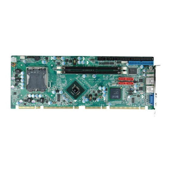
1.1 Introduction Figure 1-1: PCIE-G41A2 The PCIE-G41A2 is a PCIMG 1.3 motherboard with an 800/1066/1333 MHz front side bus. It accepts a Socket LGA775 Intel® Core™2 Duo/Quad/Extreme processor and supports two 2.0 GB (max.) 800/1066 MHz dual-channel DDR3 DIMM modules. The PCIE-G41A2 includes a VGA. -
Page 15: Connectors
Two Gigabit Ethernet connectors Four SATA connectors High Definition audio with optional audio kit Intel® GMA X4500 for DX10 and OpenGL 1.5 support 1.4 Connectors The connectors on the PCIE-G41A2 are shown in the figure below. Figure 1-2: Connectors Page 3... -
Page 16: Dimensions
PCIE-G41A2 PICMG 1.3 CPU card 1.5 Dimensions The main dimensions of the PCIE-G41A2 are shown in the diagram below. Figure 1-3: PCIE-G41A2 Dimensions (mm) Page 4... -
Page 17: Data Flow
PCIE-G41A2 PICMG 1.3 CPU card 1.6 Data Flow F igure 1-4 shows the data flow between the system chipset, the CPU and other components installed on the motherboard. Figure 1-4: Data Flow Diagram Page 5... -
Page 18: Technical Specifications
PCIE-G41A2 PICMG 1.3 CPU card 1.7 Technical Specifications PCIE-G41A2 technical specifications are listed in T able 1-1. Specification/Model PCIE-G41A2 PICMG 1.3 Form Factor Socket LGA775 Intel® Core™2 Duo/Quad/Extreme, CPU Supported Socket LGA775 Intel® Celeron® Front Side Bus (FSB) 800 MHz, 1066 MHz or 1333 MHz Northbridge Chipset Intel®... -
Page 19: Table 1-1: Pcie-G41A2 Specifications
PCIE-G41A2 PICMG 1.3 CPU card Specification/Model PCIE-G41A2 One PS/2 KB/MS connector Keyboard/Mouse Parallel Port One internal IEEE 1284 parallel connector (supports normal, EPP and ECP modes) Serial Ports Two RS-232 serial port connectors USB 2.0/1.1 ports Two external USB ports... -
Page 20: Packing List
PCIE-G41A2 PICMG 1.3 CPU card Chapter Packing List Page 8... -
Page 21: Anti-Static Precautions
Only handle the edges of the PCB: Don't touch the surface of the motherboard. Hold the motherboard by the edges when handling. 2.2 Unpacking Precautions When the PCIE-G41A2 is unpacked, please do the following: Follow the antistatic guidelines above. Make sure the packing box is facing upwards when opening. -
Page 22: Packing List
NOTE: If any of the components listed in the checklist below are missing, do not proceed with the installation. Contact the IEI reseller or vendor the PCIE-G41A2 was purchased from or contact an IEI sales representative directly by sending an email to ales@iei.com.tw. -
Page 23: Optional Items
PCIE-G41A2 PICMG 1.3 CPU card Quantity Item and Part Number Image Quick Installation Guide Table 2-1: Packing List 2.4 Optional Items The following are optional components which may be separately purchased: Item and Part Number Image CPU cooler kit (P/N: CF-520-RS-R11) -
Page 24: Table 2-2: Optional Items
PCIE-G41A2 PICMG 1.3 CPU card Item and Part Number Image Audio kit_ 5.1 Channel (P/N: AC-KIT08R-R10) Audio kit_ 7.1 Channel (P/N: AC-KIT-883HD-R10) PS2 cable (P/N: 19800-000075-RS) 4-port USB cable (P/N: CB-USB14-RS) SATA power cable (P/N: 32102-000100-100-RS P/N: 32102-000100-200-RS) Table 2-2: Optional Items... -
Page 25: Connectors
PCIE-G41A2 PICMG 1.3 CPU card Chapter Connectors Page 13... -
Page 26: Peripheral Interface Connectors
PCIE-G41A2 PICMG 1.3 CPU card 3.1 Peripheral Interface Connectors This chapter details all the jumpers and connectors. 3.1.1 PCIE-G41A2 Layout The figure below shows all the connectors and jumpers. Figure 3-1: Connectors and Jumpers 3.1.2 Peripheral Interface Connectors The table below lists all the connectors on the board. -
Page 27: External Interface Panel Connectors
PCIE-G41A2 PICMG 1.3 CPU card Connector Type Label Infrared interface connector 5-pin header Keyboard/Mouse connector 6-pin wafer MS/KB1 Parallel ATA connector (IDE) 40-pin box header PIDE1 Parallel port connector 26-pin box header LPT1 Serial port connector 10-pin box header COM1... -
Page 28: Internal Peripheral Connectors
PCIE-G41A2 PICMG 1.3 CPU card 3.2 Internal Peripheral Connectors The section describes all of the connectors on the PCIE-G41A2. 3.2.1 Audio Kit Connector CN Label: J_AUDIO1 9-pin header CN Type: CN Location: See Figure 3-2 CN Pinouts: See Table 3-3 This connector connects to an external audio kit. -
Page 29: Battery Connector
PCIE-G41A2 PICMG 1.3 CPU card 3.2.2 Battery Connector CN Label: BAT1 2-pin wafer CN Type: CN Location: See Figure 3-3 CN Pinouts: See Table 3-4 This is connected to the system battery. The battery provides power to the system clock to retain the time when power is turned off. -
Page 30: Cpu Power Input Connector
PCIE-G41A2 PICMG 1.3 CPU card Figure 3-4: CPU Fan Connector Location PIN NO. DESCRIPTION +12 V Rotation Signal Control Table 3-5: CPU Fan Connector Pinouts 3.2.4 CPU Power Input Connector CN Label: CPU12V1 CN Type: 4-pin connector CN Location: See Figure 3-5... -
Page 31: Digital I/O Connector
PCIE-G41A2 PICMG 1.3 CPU card Figure 3-5: CPU Power Input Connector Location PIN NO. DESCRIPTION +12 V +12 V Table 3-6: CPU Power Input Connector Pinouts 3.2.5 Digital I/O Connector CN Label: DIO1 10-pin header CN Type: CN Location: See Figure 3-6... -
Page 32: Floppy Disk Connector
PCIE-G41A2 PICMG 1.3 CPU card Figure 3-6: Digital I/O Connector Locations PIN NO. DESCRIPTION PIN NO. DESCRIPTION Output 3 Output 2 Output 1 Output 0 Input 3 Input 2 Input 1 Input 0 Table 3-7: Digital I/O Connector Pinouts 3.2.6 Floppy Disk Connector... -
Page 33: Figure 3-7: Floppy Drive Connector Location
PCIE-G41A2 PICMG 1.3 CPU card Figure 3-7: Floppy Drive Connector Location Description Description REDUCE WRITE INDEX# MOTOR ENABLE A# DRIVE SELECT B# DRIVE SELECT A# MOTOR ENABLE B# DIRECTION# STEP# WRITE DATA# WRITE GATE# TRACK 0# WRITE PROTECT# READ DATA#... -
Page 34: Front Panel Connector
PCIE-G41A2 PICMG 1.3 CPU card 3.2.7 Front Panel Connector CN Label: F_PANEL1 14-pin header CN Type: CN Location: See Figure 3-8 CN Pinouts: See Table 3-9 The front panel connector connects to the indicator LEDs and buttons on the computer's front panel. -
Page 35: Infrared Interface Connector
PCIE-G41A2 PICMG 1.3 CPU card 3.2.8 Infrared Interface Connector CN Label: 5-pin header CN Type: CN Location: See Figure 3-9 CN Pinouts: See Table 3-10 The infrared connector attaches to an infrared receiver for use with remote controls. Figure 3-9: Infrared Connector Location... -
Page 36: Memory Card Slot
PCIE-G41A2 PICMG 1.3 CPU card The keyboard/mouse connector connects to a PS/2 Y-cable that can be connected to a PS/2 keyboard and mouse. Figure 3-10: Keyboard/Mouse Connector Location Description +5 V Mouse Data Mouse Clock Keyboard Data Keyboard Clock Ground Table 3-11: Keyboard/Mouse Connector Pinouts 3.2.10 Memory Card Slot... -
Page 37: Parallel Ata (Ide) Connector
PCIE-G41A2 PICMG 1.3 CPU card Figure 3-11: Memory Card Slot Location 3.2.11 Parallel ATA (IDE) Connector CN Label: IDE1 CN Type: 40-pin box header CN Location: See Figure 3-12 See Table 3-12 CN Pinouts: The Parallel ATA (IDE) connector can connect to a Parallel ATA (IDE) hard drive or optical device. -
Page 38: Parallel Port Connector
PCIE-G41A2 PICMG 1.3 CPU card Description Description RESET# DATA 7 DATA 8 DATA 6 DATA 9 DATA 5 DATA 10 DATA 4 DATA 11 DATA 3 DATA 12 DATA 2 DATA 13 DATA 1 DATA 14 DATA 0 DATA 15... -
Page 39: Sata Drive Connectors
PCIE-G41A2 PICMG 1.3 CPU card Figure 3-13: Parallel Port Connector Location Description Description STROBE# DATA 0 DATA 1 DATA 2 DATA 3 DATA 4 DATA 5 DATA 6 DATA 7 ACKNOWLEDGE BUSY PAPER EMPTY PRINTER SELECT AUTO FORM FEED #... -
Page 40: Serial Port Connector
PCIE-G41A2 PICMG 1.3 CPU card The SATA drive connectors can be connected to SATA drives. Figure 3-14: SATA Drive Connector Location 3.2.14 Serial Port Connector CN Label: COM1, COM2 CN Type: 10-pin header (2x5) CN Location: See Figure 3-15 CN Pinouts: See Table 3-14 This connector provides RS-232 communications. -
Page 41: Spi Flash Connector
PCIE-G41A2 PICMG 1.3 CPU card 3.2.15 SPI Flash Connector CN Label: JSPI1 8-pin header (2x4) CN Type: CN Location: See Figure 3-16 CN Pinouts: See Table 3-15 The 8-pin SPI Flash connector is used to flash the BIOS. Figure 3-16: SPI Flash Connector... -
Page 42: Usb Connector
If an SDVO graphics card is installed on the PCIe x16 expansion slot on the backplane, the 1x3 pin Serial Digital Video Output (SDVO) control connector must be connected to a corresponding SDVO control connector on a compatible IEI backplane. Figure 3-17:SDVO Connector Pinout Locations PIN NO. -
Page 43: External Peripheral Interface Connector Panel
PCIE-G41A2 PICMG 1.3 CPU card Figure 3-18: USB Connector Pinout Locations PIN NO. DESCRIPTION PIN NO. DESCRIPTION DATA- DATA+ DATA+ DATA- Table 3-17: USB Port Connector Pinouts 3.3 External Peripheral Interface Connector Panel The figure below shows the external peripheral interface connector (EPIC) panel. The... -
Page 44: Lan Connector
PCIE-G41A2 PICMG 1.3 CPU card 3.3.1 LAN Connector CN Label: LAN1, LAN2 RJ-45 CN Type: CN Location: See Figure 3-19 CN Pinouts: See Table 3-18 The LAN connector connects to a local network. DESCRIPTION DESCRIPTION MDIA3- MDIA1+ MDIA3+ MDIA2+- MDIA2-... -
Page 45: Vga Connector
PCIE-G41A2 PICMG 1.3 CPU card 3.3.3 VGA Connector CN Label: VGA1 15-pin Female CN Type: CN Location: See Figure 3-19 CN Pinouts: See Figure 3-20 and Table 3-20 The VGA connector connects to a monitor that accepts a standard VGA input. -
Page 46: Installation
PCIE-G41A2 PICMG 1.3 CPU card Chapter Installation Page 34... -
Page 47: Anti-Static Precautions
Electrostatic discharge (ESD) can cause serious damage to electronic components, including the PCIE-G41A2. Dry climates are especially susceptible to ESD. It is therefore critical that whenever the PCIE-G41A2 or any other electrical component is handled, the following anti-static precautions are strictly adhered to. - Page 48 This helps to prevent potential ESD damage. Turn all power to the PCIE-G41A2 off: When working with the PCIE-G41A2, make sure that it is disconnected from all power supplies and that no electricity is being fed into the system.
-
Page 49: Socket Lga775 Cpu Installation
PCIE-G41A2 PICMG 1.3 CPU card 4.2.1 Socket LGA775 CPU Installation NOTE: To enable Hyper-Threading, the CPU and chipset must both support it. WARNING: CPUs are expensive and sensitive components. When installing the CPU please be careful not to damage it in anyway. Make sure the CPU is installed properly and ensure the correct cooling kit is properly installed. -
Page 50: Figure 4-2: Remove Protective Cover
PCIE-G41A2 PICMG 1.3 CPU card Step 1: Remove the protective cover. The black protective cover can be removed by pulling up on the tab labeled "Remove". See Figure 4-2. Figure 4-2: Remove Protective Cover Step 2: Open the socket. Disengage the load lever by pressing the lever down and slightly outward to clear the retention tab. -
Page 51: Figure 4-4: Insert The Socket Lga775 Cpu
PCIE-G41A2 PICMG 1.3 CPU card Step 4: Orientate the CPU properly. The contact array should be facing the CPU socket. Step 5: Correctly position the CPU. Match the Pin 1 mark with the cut edge on the CPU socket. Step 6: Align the CPU pins. -
Page 52: Socket Lga775 Cooling Kit Installation
DO NOT use the original Intel® heat sink and fan. A proprietary one is recommended. Figure 4-5: Cooling Kits (CF-520 and CF-775A) The cooling kit can be bought from IEI. The cooling kit has a heatsink and fan. WARNING: Do not wipe off (accidentally or otherwise) the pre-sprayed layer of thermal paste on the bottom of the heat sink. -
Page 53: Figure 4-6: Securing The Heat Sink To The Pcie-G41A2
Step 6: Connect the fan cable. Connect the cooling kit fan cable to the fan connector on the PCIE-G41A2. Carefully route the cable and avoid heat generating chips and fan blades. Step 0:... -
Page 54: Dimm Installation
0: 4.2.4 Backplane Installation Before the PCIE-G41A2 can be installed into the chassis, a backplane must first be installed. Please refer to the installation instructions that came with the backplane and the chassis to see how to install the backplane into the chassis. -
Page 55: Cpu Card Installation
4.2.5 CPU Card Installation To install the PCIE-G41A2 CPU card onto the backplane, carefully align the CPU card interface connectors with the corresponding socket on the backplane. To do this, please refer to the reference material that came with the backplane. Next, secure the CPU card to the chassis. -
Page 56: Clear Cmos Jumper
PCIE-G41A2 PICMG 1.3 CPU card Description Label Type Clear CMOS jumper J_CMOS1 3-pin header Table 4-1: Jumpers 4.3.1 Clear CMOS Jumper Jumper Label: J_CMOS1 Jumper Type: 3-pin header Jumper Settings: See Table 4-2 Jumper Location: See Figure 4-8 To reset the BIOS, move the jumper to the "Clear BIOS" position for 3 seconds or more, and then move back to the default position. -
Page 57: Sata Drive Connection
Step 0: 4.4.2 SATA Drive Connection The PCIE-G41A2 is shipped with two SATA drive cables and one SATA drive power cable. To connect the SATA drives to the connectors, please follow the steps below. Page 45... -
Page 58: Figure 4-10: Sata Drive Cable Connection
PCIE-G41A2 PICMG 1.3 CPU card Step 1: Locate the connectors. The locations of the SATA drive connectors are shown in Chapter 3. Step 2: Insert the cable connector. Press the clip on the connector at the end of the SATA cable and insert the cable connector into the on-board SATA drive connector. -
Page 59: Usb Cable (Dual Port) With Slot Bracket
PCIE-G41A2 PICMG 1.3 CPU card Figure 4-11: SATA Power Drive Connection 4.4.3 USB Cable (Dual Port) with Slot Bracket The PCIE-G41A2 is shipped with a dual port USB 2.0 cable. To connect the USB cable connector, please follow the steps below. Step 1: Locate the connectors. -
Page 60: External Peripheral Interface Connection
Step 3: Insert the cable connectors. Once the cable connectors are properly aligned with the USB connectors on the PCIE-G41A2, connect the cable connectors to the on-board connectors. See Figure 4-12. Figure 4-12: Dual USB Cable Connection Step 4: Attach the bracket to the chassis. The USB 2.0 connectors are attached to a bracket. -
Page 61: Usb Connection (Dual Connector)
PCIE-G41A2 PICMG 1.3 CPU card Step 2: Align the connectors. Align the RJ-45 connector on the LAN cable with one of the RJ-45 connectors on the PCIE-G41A2. See Figure 4-13. Figure 4-13: LAN Connection Step 3: Insert the LAN cable RJ-45 connector. Once aligned, gently insert the LAN cable RJ-45 connector into the on-board RJ-45 connector. -
Page 62: Vga Monitor Connection
Figure 4-14: USB Connector 4.5.3 VGA Monitor Connection The PCIE-G41A2 has a single female DB-15 connector on the external peripheral interface panel. The DB-15 connector is connected to a CRT or VGA monitor. To connect a monitor to the PCIE-G41A2, please follow the instructions below. -
Page 63: Software Installation
Step 0: 4.6 Software Installation All the drivers for the PCIE-G41A2 are on the CD that came with the system. To install the drivers, please follow the steps below. Step 1: Insert the CD into a CD drive connected to the system. -
Page 64: Figure 4-16: Introduction Screen
PCIE-G41A2 PICMG 1.3 CPU card Figure 4-16: Introduction Screen Step 3: Click PCIE-G41A2. Step 4: A new screen with a list of available drivers appears (Figure 4-17). Figure 4-17: Available Drivers Step 5: Install all of the necessary drivers in this menu. -
Page 65: Bios
PCIE-G41A2 PICMG 1.3 CPU card Chapter BIOS Page 53... -
Page 66: Introduction
PCIE-G41A2 PICMG 1.3 CPU card 5.1 Introduction The BIOS is programmed onto the BIOS chip. The BIOS setup program allows changes to certain system settings. This chapter outlines the options that can be changed. 5.1.1 Starting Setup The AMI BIOS is activated when the computer is turned on. The setup program can be activated in one of two ways. -
Page 67: Getting Help
PCIE-G41A2 PICMG 1.3 CPU card Function F2 /F3 key Change color from total 16 colors. F2 to select color forward. F10 key Save all the CMOS changes, only for Main Menu Table 5-1: BIOS Navigation Keys 5.1.3 Getting Help When F1 is pressed a small help window describing the appropriate keys to use and the possible selections for the highlighted item appears. -
Page 68: Main
PCIE-G41A2 PICMG 1.3 CPU card 5.2 Main The Main BIOS menu (BIOS Menu 1) appears when the BIOS Setup program is entered. The Main menu gives an overview of the basic system information. BIOS SETUP UTILITY Main Advanced PCIPNP Boot... -
Page 69: Advanced
PCIE-G41A2 PICMG 1.3 CPU card The System Overview field also has two user configurable fields: System Time [xx:xx:xx] Use the System Time option to set the system time. Manually enter the hours, minutes and seconds. System Date [xx/xx/xx] Use the System Date option to set the system date. Manually enter the day, month and year. -
Page 70: Cpu Configuration
PCIE-G41A2 PICMG 1.3 CPU card BIOS SETUP UTILITY Main Advanced PCIPNP Boot Security Chipset Exit Advanced Settings Configure CPU ⎯⎯⎯⎯⎯⎯⎯⎯⎯⎯⎯⎯⎯⎯⎯⎯⎯⎯⎯⎯⎯⎯⎯⎯⎯⎯⎯⎯⎯⎯⎯ WARNING: Setting wrong values in below sections may cause system to malfunction > CPU Configuration > IDE Configuration > Floppy Configuration Select Screen >... -
Page 71: Ide Configuration
PCIE-G41A2 PICMG 1.3 CPU card Brand String: Lists the brand name of the CPU being used Frequency: Lists the CPU processing speed FSB Speed: Lists the FSB speed Cache L1: Lists the CPU L1 cache size Cache L2: Lists the CPU L2 cache size 5.3.2 IDE Configuration... -
Page 72: Configure Sata As [Ide]
PCIE-G41A2 PICMG 1.3 CPU card Compatible Configures the on-board ATA/IDE controller to be in compatible mode. In this mode, a SATA channel will replace one of the IDE channels. This mode supports up to 4 storage devices. Configures the on-board ATA/IDE controller to be in... -
Page 73: Ide Master, Ide Slave
PCIE-G41A2 PICMG 1.3 CPU card Secondary IDE Slave Third IDE Master Third IDE Slave The IDE Configuration menu (BIOS Menu 4) allows changes to the configurations for the IDE devices installed in the system. If an IDE device is detected and one of the above listed four BIOS configuration options are selected, the IDE configuration options shown in Section 5.3.2.1 appear. -
Page 74: Type [Auto]
PCIE-G41A2 PICMG 1.3 CPU card Size: List the storage capacity of the device. LBA Mode: Indicates whether the LBA (Logical Block Addressing) is a method of addressing data on a disk drive is supported or not. Block Mode: Block mode boosts IDE drive performance by increasing the amount of data transferred. -
Page 75: Lba/Large Mode [Auto]
PCIE-G41A2 PICMG 1.3 CPU card LBA/Large Mode [Auto] Use the LBA/Large Mode option to disable or enable BIOS to auto detects LBA (Logical Block Addressing). LBA is a method of addressing data on a disk drive. In LBA mode, the maximum drive capacity is 137 GB. -
Page 76: Dma Mode [Auto]
PCIE-G41A2 PICMG 1.3 CPU card PIO mode 3 selected with a maximum transfer rate of 11.1 MB/s PIO mode 4 selected with a maximum transfer rate of 16.6 MB/s (This setting generally works with all hard disk drives manufactured after 1999. For other disk drives, such as IDE CD-ROM drives, check the specifications of the drive.) -
Page 77: Floppy Configuration
PCIE-G41A2 PICMG 1.3 CPU card 5.3.3 Floppy Configuration Use the Floppy Configuration menu to configure the floppy disk drive connected to the system. BIOS SETUP UTILITY Main Advanced PCIPNP Boot Security Chipset Exit Floppy Configuration Select the type of floppy ⎯⎯⎯⎯⎯⎯⎯⎯⎯⎯⎯⎯⎯⎯⎯⎯⎯⎯⎯⎯⎯⎯⎯⎯⎯⎯⎯⎯⎯⎯⎯... -
Page 78: Super Io Configuration
PCIE-G41A2 PICMG 1.3 CPU card 5.3.4 Super IO Configuration Use the Super IO Configuration menu (BIOS Menu 7) to set or change the configurations for the FDD controllers, parallel ports and serial ports. BIOS SETUP UTILITY Main Advanced PCIPNP Boot... -
Page 79: Parallel Port Irq [Irq7]
PCIE-G41A2 PICMG 1.3 CPU card Bi-directional Parallel port outputs are 8-bits long. Inputs are accomplished by reading 4 of the 8 bits on the status register. The parallel port operates in the enhanced parallel port mode (EPP). The EPP mode supports... -
Page 80: Serial Port1 Mode [Normal]
PCIE-G41A2 PICMG 1.3 CPU card 2E8/IRQ3 Serial Port 1 I/O port address is 2E8 and the interrupt address is IRQ3 Serial Port1 Mode [Normal] Use the Serial Port1 Mode option to select the transmitting and receiving mode for the first serial port. -
Page 81: Hardware Health Configuration
PCIE-G41A2 PICMG 1.3 CPU card 5.3.5 Hardware Health Configuration The Hardware Health Configuration menu (BIOS Menu 8) shows the operating temperature, fan speeds and system voltages. BIOS SETUP UTILITY Main Advanced PCIPNP Boot Security Chipset Exit Hardware Health Event Monitoring ⎯⎯⎯⎯⎯⎯⎯⎯⎯⎯⎯⎯⎯⎯⎯⎯⎯⎯⎯⎯⎯⎯⎯⎯⎯⎯⎯⎯⎯⎯⎯... -
Page 82: Temp. Limit Of Off [000]
PCIE-G41A2 PICMG 1.3 CPU card Temp. Limit of OFF [000] WARNING: CPU failure can result if this value is set too high The fan will turn off if the temperature falls below this value. Minimum Value: 0°C Maximum Value: 127°C Temp. -
Page 83: Fan Pwm Control [100]
PCIE-G41A2 PICMG 1.3 CPU card 1 PWM 2 PWM 4 PWM 8 PWM 15 PWM Fan PWM Control [100] This value specifies the speed of the fan. PWM Minimum Mode: 0 PWM Maximum Mode: 127 Hardware Health Monitoring The following system parameters and values are shown. The system parameters that are... -
Page 84: Power Configuration
PCIE-G41A2 PICMG 1.3 CPU card 5.3.6 Power Configuration Use the Power Configuration menu (BIOS Menu 10) configures the Advanced Configuration and Power Interface (ACPI) and Power Management (APM) options. BIOS SETUP UTILITY Main Advanced PCIPNP Boot Security Chipset Exit ⎯⎯⎯⎯⎯⎯⎯⎯⎯⎯⎯⎯⎯⎯⎯⎯⎯⎯⎯⎯⎯⎯⎯⎯⎯⎯⎯⎯⎯⎯⎯... -
Page 85: Bios Menu 10: Acpi Settings
PCIE-G41A2 PICMG 1.3 CPU card BIOS SETUP UTILITY Main Advanced PCIPNP Boot Security Chipset Power Exit ACPI Settings ⎯⎯⎯⎯⎯⎯⎯⎯⎯⎯⎯⎯⎯⎯⎯⎯⎯⎯⎯⎯⎯⎯⎯⎯⎯⎯⎯⎯⎯⎯⎯ Suspend mode [S1 (POS)] Select Screen ↑ ↓ Select Item Enter Go to SubScreen General Help Save and Exit Exit v02.61 ©Copyright 1985-2006, American Megatrends, Inc. -
Page 86: Apm Configuration
PCIE-G41A2 PICMG 1.3 CPU card 5.3.6.2 APM Configuration The APM Configuration menu (BIOS Menu 11) allows the advanced power management options to be configured. BIOS SETUP UTILITY Main Advanced PCIPNP Boot Security Chipset Exit APM Configuration Go into On/Off, or ⎯⎯⎯⎯⎯⎯⎯⎯⎯⎯⎯⎯⎯⎯⎯⎯⎯⎯⎯⎯⎯⎯⎯⎯⎯⎯⎯⎯⎯⎯⎯... -
Page 87: Resume On Ring [Disabled]
PCIE-G41A2 PICMG 1.3 CPU card Disabled Wake event not generated by activity on the EFAULT keyboard or mouse Wake event generated by activity on the keyboard Resume KeyBoard Resume Wake event generated by activity on the mouse Mouse Enabled Wake event generated by activity on the keyboard or... -
Page 88: Remote Access Configuration
PCIE-G41A2 PICMG 1.3 CPU card Resume On RTC Alarm [Disabled] Use the Resume On RTC Alarm option to specify the time the system should be roused from a suspended state. Disabled The real time clock (RTC) cannot generate a wake... -
Page 89: Remote Access [Disabled]
PCIE-G41A2 PICMG 1.3 CPU card Remote Access [Disabled] Use the Remote Access option to enable or disable access to the remote functionalities of the system. Disabled Remote access is disabled. EFAULT Remote access configuration options shown below Enabled appear: Serial Port Number... -
Page 90: Redirection After Bios Post [Always]
PCIE-G41A2 PICMG 1.3 CPU card 19200 8,n,1 09600 8,n,1 NOTE: Identical baud rate setting musts be set on the host (a management computer running a terminal software) and the slave Redirection After BIOS POST [Always] Use the Redirection After BIOS POST option to specify when console redirection should occur. -
Page 91: Usb Configuration
PCIE-G41A2 PICMG 1.3 CPU card 5.3.8 USB Configuration Use the USB Configuration menu (BIOS Menu 13) to read USB configuration information and configure the USB settings. BIOS SETUP UTILITY Main Advanced PCIPNP Boot Security Chipset Exit USB Configuration Enables USB host ⎯⎯⎯⎯⎯⎯⎯⎯⎯⎯⎯⎯⎯⎯⎯⎯⎯⎯⎯⎯⎯⎯⎯⎯⎯⎯⎯⎯⎯⎯⎯... -
Page 92: Usb 2.0 Controller [Enabled]
PCIE-G41A2 PICMG 1.3 CPU card USB 2.0 Controller [Enabled] Use the USB 2.0 Controller BIOS option to enable or disable the USB 2.0 controller USB 2.0 controller enabled Enabled EFAULT Disabled USB 2.0 controller disabled Legacy USB Support [Enabled] Use the Legacy USB Support BIOS option to enable USB mouse and USB keyboard support. -
Page 93: Pci/Pnp
PCIE-G41A2 PICMG 1.3 CPU card 5.4 PCI/PnP Use the PCI/PnP menu (BIOS Menu 14) to configure advanced PCI and PnP settings. WARNING! Setting wrong values for the BIOS selections in the PCIPnP BIOS menu may cause the system to malfunction. -
Page 94: Dma Channel# [Available]
PCIE-G41A2 PICMG 1.3 CPU card Available The specified IRQ is available to be used by EFAULT PCI/PnP devices The specified IRQ is reserved for use by Legacy ISA Reserved devices Available IRQ addresses are: IRQ3 IRQ4 IRQ5 IRQ7 IRQ9 IRQ10... -
Page 95: Boot
PCIE-G41A2 PICMG 1.3 CPU card Reserved Memory Size [Disabled] Use the Reserved Memory Size BIOS option to specify the amount of memory that should be reserved for legacy ISA devices. Disabled No memory block reserved for legacy ISA devices EFAULT... -
Page 96: Boot Settings Configuration
PCIE-G41A2 PICMG 1.3 CPU card 5.5.1 Boot Settings Configuration Use the Boot Settings Configuration menu (BIOS Menu 16) to configure advanced system boot options. BIOS SETUP UTILITY Main Advanced PCIPNP Boot Security Chipset Exit Boot Settings Configuration Allows BIOS to skip ⎯⎯⎯⎯⎯⎯⎯⎯⎯⎯⎯⎯⎯⎯⎯⎯⎯⎯⎯⎯⎯⎯⎯⎯⎯⎯⎯⎯⎯⎯⎯... -
Page 97: Addon Rom Display Mode [Force Bios]
PCIE-G41A2 PICMG 1.3 CPU card AddOn ROM Display Mode [Force BIOS] Use the AddOn ROM Display Mode option to allow add-on ROM (read-only memory) messages to be displayed. Force BIOS The system forces third party BIOS to display EFAULT during system boot. -
Page 98: Boot Device Priority
PCIE-G41A2 PICMG 1.3 CPU card 5.5.2 Boot Device Priority Use the Boot Device Priority menu (BIOS Menu 17) to specify the boot sequence from the available devices. The drive sequence also depends on the boot sequence in the individual device section. -
Page 99: Hard Disk Drives
PCIE-G41A2 PICMG 1.3 CPU card 5.5.3 Hard Disk Drives Use the Hard Disk Drives menu to specify the boot sequence of the available HDDs. Only installed hard drives are shown. BIOS SETUP UTILITY Main Advanced PCIPNP Boot Security Chipset Exit... -
Page 100: Removable Drives
PCIE-G41A2 PICMG 1.3 CPU card 5.5.4 Removable Drives Use the Removable Drives menu (BIOS Menu 19) to specify the boot sequence of the removable drives. Only connected drives are shown. BIOS SETUP UTILITY Main Advanced PCIPNP Boot Security Chipset Exit... -
Page 101: Security
PCIE-G41A2 PICMG 1.3 CPU card The boot sequence from the available devices is selected. If the “1st Drive” option is selected a list of available CD/DVD drives is shown. Select the first CD/DVD drive the system boots from. If the “1st Drive” is not used for booting this option may be disabled. -
Page 102: Chipset
PCIE-G41A2 PICMG 1.3 CPU card Change Supervisor Password Use the Change Supervisor Password to set or change a supervisor password. The default for this option is Not Installed. If a supervisor password must be installed, select this field and enter the password. After the password has been added, Install appears next to Change Supervisor Password. -
Page 103: Northbridge Configuration
PCIE-G41A2 PICMG 1.3 CPU card BIOS SETUP UTILITY Main Advanced PCIPNP Boot Security Chipset Exit Advanced Chipset Settings ⎯⎯⎯⎯⎯⎯⎯⎯⎯⎯⎯⎯⎯⎯⎯⎯⎯⎯⎯⎯⎯⎯⎯⎯⎯⎯⎯⎯⎯⎯⎯ WARNING: Setting wrong values in below section may cause system to malfunction. > Northbridge Configuration > Southbridge Configuration Select Screen ↑ ↓... -
Page 104: Memory Remap Feature [Enabled]
PCIE-G41A2 PICMG 1.3 CPU card Memory Remap Feature [Enabled] Use the Memory Remap Feature option to allow the overlapped PCI memory above the total physical memory to be remapped. Disabled Overlapped PCI memory cannot be remapped Overlapped PCI memory can be remapped... -
Page 105: Southbridge Configuration
PCIE-G41A2 PICMG 1.3 CPU card Disable 32 MB of memory used by internal graphics device Enable, 32 MB EFAULT Enable, 64 MB 64 MB of memory used by internal graphics device Enable, 128 MB 128 MB of memory used by internal graphics device 5.7.2 Southbridge Configuration... -
Page 106: Exit
PCIE-G41A2 PICMG 1.3 CPU card modulates changes in the extreme values from spikes to flat curves, thus reducing the EMI. This benefit may in some cases be outweighed by problems with timing-critical devices, such as a clock-sensitive SCSI device. Disabled... -
Page 107: Discard Changes
PCIE-G41A2 PICMG 1.3 CPU card Discard Changes Use the Discard Changes option to discard the changes and remain in the BIOS configuration setup program. Load Optimal Defaults Use the Load Optimal Defaults option to load the optimal default values for each of the parameters on the Setup menus. -
Page 108: Abios Options
PCIE-G41A2 PICMG 1.3 CPU card Appendix BIOS Options Page 96... - Page 109 PCIE-G41A2 PICMG 1.3 CPU card Below is a list of BIOS configuration options in the BIOS chapter. System Overview .........................56 System Time [xx:xx:xx] .......................57 System Date [xx/xx/xx] ......................57 ATA/IDE Configurations [Compatible]................59 Configure SATA as [IDE].....................60 ...
- Page 110 PCIE-G41A2 PICMG 1.3 CPU card Resume on Ring [Disabled] ....................75 Resume on PCI PME# [Disabled] ..................75 Resume on PCI-Express WAKE# [Enabled]..............75 Resume On RTC Alarm [Disabled]..................76 Remote Access [Disabled]....................77 Serial Port Number [COM1]....................77 ...
- Page 111 PCIE-G41A2 PICMG 1.3 CPU card Load Optimal Defaults......................95 Load Failsafe Defaults......................95 Page 99...
- Page 112 PCIE-G41A2 PICMG 1.3 CPU card Page 100...
-
Page 113: B One Key Recovery
PCIE-G41A2 PICMG 1.3 CPU card Appendix One Key Recovery Page 101... -
Page 114: One Key Recovery Introduction
PCIE-G41A2 PICMG 1.3 CPU card B.1 One Key Recovery Introduction The IEI one key recovery is an easy-to-use front end for the Norton Ghost system backup and recovery tool. The one key recovery provides quick and easy shortcuts for creating a backup and reverting to that backup or for reverting to the factory default settings. - Page 115 PCIE-G41A2 PICMG 1.3 CPU card Windows 7 Windows CE 5.0 Windows CE 6.0 Windows XP Embedded Linux Fedora Core 12 (Constantine) Fedora Core 11 (Leonidas) Fedora Core 10 (Cambridge) Fedora Core 8 (Werewolf) Fedora Core 7 (Moonshine) RedHat RHEL-5.4 RedHat 9 (Ghirke) Ubuntu 8.10 (Intrepid)
-
Page 116: Setup Procedure For Windows
PCIE-G41A2 PICMG 1.3 CPU card NOTE: The recovery CD can only be used with IEI products. The software will fail to run and a warning message will appear when used on non-IEI hardware. B.2 Setup Procedure for Windows Prior to using the recovery tool to backup or restore system, a few setup procedures are required. -
Page 117: Hardware And Bios Setup
Step 2: Install a hard driver or SSD in the PCIE-G41A2. An unformatted and unpartitioned disk is recommended. Step 3: Connect an optical disk drive to the PCIE-G41A2 and insert the recovery CD. Step 4: Turn on the system. Step 5: Press the <DELETE>... -
Page 118: Figure B-1: Recovery Tool Setup Menu
PCIE-G41A2 PICMG 1.3 CPU card Figure B-1: Recovery Tool Setup Menu Step 5: Press <5> then <Enter>. Figure B-2: Command Mode Step 6: The command prompt window appears. Type the following commands (marked in red) to create two partitions. One is for the OS installation; the other is for saving recovery files and images which will be an invisible partition. -
Page 119: Figure B-3: Partition Creation Commands
PCIE-G41A2 PICMG 1.3 CPU card system32>format F: /fs:ntfs /q /v:Recovery /y system32>exit Figure B-3: Partition Creation Commands Page 107... -
Page 120: Install Operating System, Drivers And Applications
PCIE-G41A2 PICMG 1.3 CPU card NOTE: Use the following commands to check if the partitions were created successfully. Step 7: Press any key to exit the recovery tool and automatically reboot the system. Please continue to the following procedure: Build-up Recovery Partition.S t e p 0 :... -
Page 121: Figure B-4: System Configuration For Windows
PCIE-G41A2 PICMG 1.3 CPU card Step 2: Start the system. Step 3: Press any key to boot from the recovery CD. It will take a while to launch the recovery tool. Please be patient. Step 4: When the recovery tool setup menu appears, press <2> then <Enter>. -
Page 122: Figure B-5: Build-Up Recovery Partition
PCIE-G41A2 PICMG 1.3 CPU card Figure B-5: Build-up Recovery Partition Step 6: After completing the system configuration, press any key in the following window to reboot the system. Figure B-6: Press any key to continue Step 7: Eject the recovery CD. -
Page 123: Create Factory Default Image
PCIE-G41A2 PICMG 1.3 CPU card B.2.5 Create Factory Default Image NOTE: Before creating the factory default image, please configure the system to a factory default environment, including driver and application installations. To create a factory default image, please follow the steps below. -
Page 124: Figure B-9: About Symantec Ghost Window
PCIE-G41A2 PICMG 1.3 CPU card Figure B-9: About Symantec Ghost Window Step 4: Use mouse to navigate to the option shown below (Figure B-10). Figure B-10: Symantec Ghost Path Step 5: Select the local source drive as shown in Figure B-11. Then click OK. -
Page 125: Figure B-11: Select A Local Source Drive
Select 1.2: [Recovery] NTFS drive and enter a file name called (Figure B-13). Click Save. The factory default image will then be saved in the selected recovery drive and named IEI.GHO. WARNING: The file name of the factory default image must be iei.GHO. Page 113... -
Page 126: Figure B-13: File Name To Copy Image To
PCIE-G41A2 PICMG 1.3 CPU card Figure B-13: File Name to Copy Image to Step 8: When the Compress Image screen in Figure B-14 prompts, click High to make the image file smaller. Figure B-14: Compress Image Page 114... -
Page 127: Figure B-15: Image Creation Confirmation
PCIE-G41A2 PICMG 1.3 CPU card Step 9: The Proceed with partition image creation window appears, click Yes to continue. Figure B-15: Image Creation Confirmation Step 10: The Symantec Ghost starts to create the factory default image (Figure B-16). Figure B-16: Image Creation Complete Step 11: When the image creation completes, a screen prompts as shown in Figure B-18. -
Page 128: Setup Procedure For Linux
PCIE-G41A2 PICMG 1.3 CPU card Step 12: The recovery tool main menu window is shown as below. Press any key to reboot the system. S t e p 0 : Figure B-18: Press Any Key to Continue B.3 Setup Procedure for Linux The initial setup procedures for Linux system are mostly the same with the procedure for Microsoft Windows. -
Page 129: Figure B-19: Partitions For Linux
PCIE-G41A2 PICMG 1.3 CPU card NOTE: Please reserve enough space for partition 3 for saving recovery images. Figure B-19: Partitions for Linux Step 3: Create a recovery partition. Insert the recovery CD into the optical disk drive. Follow Step 1 Step 3 described in Section B.2.2. -
Page 130: Figure B-20: System Configuration For Linux
PCIE-G41A2 PICMG 1.3 CPU card recovery partition. After completing the system configuration, press any key to reboot the system. Eject the recovery CD. Figure B-20: System Configuration for Linux Step 5: Access the recovery tool main menu by modifying the “menu.lst”. To first access the recovery tool main menu, the menu.lst must be modified. -
Page 131: Recovery Tool Functions
PCIE-G41A2 PICMG 1.3 CPU card Step 7: The recovery tool menu appears. (Figure B-22) Figure B-22: Recovery Tool Menu Step 8: Create a factory default image. Follow Step 2 Step 12 described in Section B.2.5 to create a factory default image. -
Page 132: Figure B-23: Recovery Tool Main Menu
PCIE-G41A2 PICMG 1.3 CPU card Figure B-23: Recovery Tool Main Menu The recovery tool has several functions including: 1. Factory Restore: Restore the factory default image (iei.GHO) created in Section B.2.5. 2. Backup system: Create a system backup image (iei_user.GHO) which will be saved in the hidden partition. -
Page 133: Factory Restore
Type <1> and press <Enter> in the main menu. Step 2: The Symantec Ghost window appears and starts to restore the factory default. A factory default image called iei.GHO is created in the hidden Recovery partition. Figure B-24: Restore Factory Default Step 3: The screen is shown as in Figure B-25 when completed. -
Page 134: Backup System
PCIE-G41A2 PICMG 1.3 CPU card B.4.2 Backup System To backup the system, please follow the steps below. Step 1: Type <2> and press <Enter> in the main menu. Step 2: The Symantec Ghost window appears and starts to backup the system. A backup image called iei_user.GHO is created in the hidden Recovery partition. -
Page 135: Restore Your Last Backup
PCIE-G41A2 PICMG 1.3 CPU card B.4.3 Restore Your Last Backup To restore the last system backup, please follow the steps below. Step 1: Type <3> and press <Enter> in the main menu. Step 2: The Symantec Ghost window appears and starts to restore the last backup image (iei_user.GHO). -
Page 136: Manual
PCIE-G41A2 PICMG 1.3 CPU card B.4.4 Manual To restore the last system backup, please follow the steps below. Step 1: Type <4> and press <Enter> in the main menu. Step 2: The Symantec Ghost window appears. Use the Ghost program to backup or recover the system manually. -
Page 137: C Terminology
PCIE-G41A2 PICMG 1.3 CPU card Appendix Terminology Page 125... - Page 138 PCIE-G41A2 PICMG 1.3 CPU card AC ’97 Audio Codec 97 (AC’97) refers to a codec standard developed by Intel® in 1997. ACPI Advanced Configuration and Power Interface (ACPI) is an OS-directed configuration, power management, and thermal management interface. AHCI Advanced Host Controller Interface (AHCI) is a SATA Host controller register-level interface.
- Page 139 PCIE-G41A2 PICMG 1.3 CPU card DIMM Dual Inline Memory Modules are a type of RAM that offer a 64-bit data bus and have separate electrical contacts on each side of the module. The digital inputs and digital outputs are general control signals that control the on/off circuit of external devices or TTL devices.
- Page 140 PCIE-G41A2 PICMG 1.3 CPU card Random Access Memory (RAM) is volatile memory that loses data when power is lost. RAM has very fast data transfer rates compared to other storage like hard drives. SATA Serial ATA (SATA) is a serial communications bus designed for data transfers between storage devices and the computer chipsets.
-
Page 141: D Digital I/O Interface
PCIE-G41A2 PICMG 1.3 CPU card Appendix Digital I/O Interface Page 129... -
Page 142: Introduction
PCIE-G41A2 PICMG 1.3 CPU card D.1 Introduction The digital I/O is used for machine control and automation. D.2 DIO Connector Pinouts Located in the Connectors section of this document. D.3 Assembly Language Example ;************************************************** ; DIO Port: 0A21h[3:0] (4 Out) 0A22h[3:0] (4 In) ;**************************************************... -
Page 143: E Watchdog Timer
PCIE-G41A2 PICMG 1.3 CPU card Appendix Watchdog Timer Page 131... - Page 144 NOTE: The following discussion applies to DOS environment. Contact IEI support or visit the IEI website for specific drivers for other operating systems. The Watchdog Timer is provided to ensure that standalone systems can always recover from catastrophic conditions that cause the CPU to crash. This condition may have occurred by external EMIs or a software bug.
- Page 145 PCIE-G41A2 PICMG 1.3 CPU card NOTE: When exiting a program it is necessary to disable the Watchdog Timer, otherwise the system resets. EXAMPLE PROGRAM: ; INITIAL TIMER PERIOD COUNTER W_LOOP: AX, 6F02H ;setting the time-out value BL, 30 ;time-out value is 48 seconds ;...
-
Page 146: F Compatibility
PCIE-G41A2 PICMG 1.3 CPU card Appendix Compatibility Page 134... -
Page 147: Compatible Operating Systems
PCIE-G41A2 PICMG 1.3 CPU card NOTE: The compatible items described here have been tested by the IEI R&D team and found to be compatible with the PCIE-G41A2 F.1 Compatible Operating Systems The following operating systems have been successfully run on the PCIE-G41A2. -
Page 148: G Hazardous Materials Disclosure
PCIE-G41A2 PICMG 1.3 CPU card Appendix Hazardous Materials Disclosure Page 136... -
Page 149: Hazardous Materials Disclosure Table For Ipb Products Certified As Rohs Compliant Under 2002/95/Ec Without Mercury
PCIE-G41A2 PICMG 1.3 CPU card G.1 Hazardous Materials Disclosure Table for IPB Products Certified as RoHS Compliant Under 2002/95/EC Without Mercury The details provided in this appendix are to ensure that the product is compliant with the Peoples Republic of China (China) RoHS standards. The table below acknowledges the presences of small quantities of certain materials in the product, and is applicable to China RoHS only. - Page 150 PCIE-G41A2 PICMG 1.3 CPU card Part Name Toxic or Hazardous Substances and Elements Lead Mercury Cadmium Hexavalent Polybrominated Polybrominated Biphenyls Diphenyl (Pb) (Hg) (Cd) Chromium (CR(VI)) (PBB) Ethers (PBDE) Housing Display Printed Circuit Board Metal Fasteners Cable Assembly Fan Assembly...
- Page 151 PCIE-G41A2 PICMG 1.3 CPU card 此附件旨在确保本产品符合中国 RoHS 标准。以下表格标示此产品中某有毒物质的含量符 合中国 RoHS 标准规定的限量要求。 本产品上会附有”环境友好使用期限”的标签,此期限是估算这些物质”不会有泄漏或突变”的 年限。本产品可能包含有较短的环境友好使用期限的可替换元件,像是电池或灯管,这些元 件将会单独标示出来。 部件名称 有毒有害物质或元素 铅 汞 镉 六价铬 多溴联苯 多溴二苯 醚 (Pb) (Hg) (Cd) (CR(VI)) (PBB) (PBDE) 壳体 显示 印刷电路板 金属螺帽 电缆组装 风扇组装 电力供应组装 电池 O: 表示该有毒有害物质在该部件所有物质材料中的含量均在 SJ/T11363-2006 标准规定的限量要求以下。...
Need help?
Do you have a question about the PCIE-G41A2 and is the answer not in the manual?
Questions and answers