
Subscribe to Our Youtube Channel
Related Manuals for Queclink GMT100


Summary of Contents for Queclink GMT100
-
Page 1: User Manual
GMT100 User manual GMT100 GPRS/GPS Tracker User Manual TRACGMT100UM001 Revision: 1.04 http://www.queclink.com TRACGMT100UM001 -10- sales@queclink.com... - Page 2 TRACGMT100UM001 General Notes Queclink offers this information as a service to its customers, to support application and engineering efforts that use the products designed by Queclink. The information provided is based upon requirements specifically provided to Queclink by the customers. Queclink has not undertaken any indep endent search for additional relevant information, includin g any information that may be in the customer’s possession.
-
Page 3: Table Of Contents
GMT100 User Manual Contents 1. Introduction ........................7 1.1. Reference ......................7 1.2. Terms and Abbreviations ..................7 2. Product Overview ......................8 2.1. Appearance ......................8 2.2. Parts List ....................... 9 2.3. Interface Definition ....................9 3. Getting Started ......................10 3.1. - Page 4 Table 2 : Terms and Abbreviations ..................7 Table 3 : Part List ......................9 Table 4 : Description of GMT100 User Cable ..............9 Table 5 : Electrical Characteristics of Ignition Detection ..........12 Table 6 : Electrical Characteristics of the digital inputs ............ 12 Table 7 : Definition of Device status and LED .........
- Page 5 Figure 4. Typical Ignition Detection ................. 12 Figure 5. Typical Digital Input Connection ............... 13 Figure 6. Typical Analog Input Connection ..............13 Figure 7. Typical Connection with Siren ................14 Figure 8. GMT100 LED on the Case ................15 TRACGMT100UM001 - 5 -...
- Page 6 GMT100 User Manual Revision History Revision Date Author Description of change V1.00 2011-11-12 Initial V1.01 2012-09-29 Lei 1> Replace the picture on the cover 2> Add the de scription and notices of cut relay output in chapter of 3.10 3> Modify the description of t able 7 in chapter of 3.9...
-
Page 7: Introduction
850/1900, its location can be monitored in real time or be periodically tracked by a backend server or other s pecified terminals. The GMT100 has multiple input/outpu t interfaces that can be us ed for monitoring or cont rolling external devices. Based on th e... -
Page 8: Product Overview
GMT100 User Manual 2. Product Overview 2.1. Appearance Figure 1. Appearance of GMT100 TRACGMT100UM001 -10-... -
Page 9: Parts List
GMT100 Locator DATA_CABLE_M (Optional) 2.3. Interface Definition There are 8 wires on GMT100 User Cable which contain the connection for power, ignition input, digital input, analog input, siren output, cut output etc. The user cable’s definition is shown in following table. -
Page 10: Getting Started
Note: 1-External power and User USB power can be present at same time. 2-For USB port current limitation, w hen configuring GMT100 by us er cable, please let backup battery on using. There is one method to turn off GMT100. -
Page 11: Reset Key
When you finished the firmware upgrade, please press the reset key to reboot the system before configuring the terminal. 3.4. USB connector There is a USB connector on GMT100 which is beside the SIM card. With the USB connector a nd the DAT A_CABLE_M, user ca n configure the syste m or downl oad firmware. -
Page 12: Digital Input
3.7. Digital Input There is a g eneral purpose digital input whic h is the blue wire on GMT100 User Cable, and it is a negative trigg er. The digital input is r ecommended to support panic button function. -
Page 13: Analog Input
Figure 5. Typical Digital Input Connection 3.8. Analog Input There is an analog input which is the green wire on GMT100 User Cable, and the analog input voltage range is 12/24V. The following diagram shows the recommended connection. Figure 6. -
Page 14: Relay Output
20A. On GMT100 user cable one 18AWG yellow wire is connected to the relay NC contact and the other 18AWG yellow wire is connected to the relay COM contact. In certain instances the two wires will be connected together. -
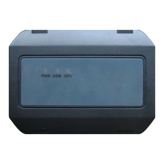
Page 15: Device Status Led
GMT100 User Manual 3.1 . Device Status LED Figure 8. GMT100 LED on the Case TRACGMT100UM001 -12 -... -
Page 16: Definition Of Device Status And Led
GMT100 User Manual Table : Definition of Device status and LED Device status LED status Device is searching GSM network Fast flashing (note1) (Note3) Device has registered to GSM network. Slow flashing (Note4) SIM card needs pin code to unlock. - Page 17 GMT100 User Manual FCC Warning: Any Changes or modifications not expressly approved by the party responsible for compliance could void the user's authority to operate the equipment. This device complies with part 15 of the FCC Rules. Operation is subject to the following two conditions: (1) This device may not cause harmful interference, and (2) this device must accept any interference received, including interference that may cause undesired operation.
Need help?
Do you have a question about the GMT100 and is the answer not in the manual?
Questions and answers