
Related Manuals for Queclink GV58CEU


Summary of Contents for Queclink GV58CEU
- Page 1 GV58CEU User Manual GV58CEU User Manual GSM/GPRS/LTE Cat1/GNSS Tracker TRACGV58CEUUM001 Version: 1.00 TRACGV58CEUUM001 – –...
- Page 2 TRACGV58CEUUM001 General Notes Queclink offers this information as a service to its customers, to support application and engineering efforts that use the products designed by Queclink. The information provided is based upon requirements specifically provided to Queclink by the customers. Queclink has not undertaken any independent search for additional relevant information, including any information that may be in the customer’s possession.
-
Page 3: Table Of Contents
2.7. Analog Input/Digital Input ....................12 2.8. 1-WIRE Interface ......................12 3. Get Started ...........................13 3.1. Parts List ..........................13 3.2. GV58CEU External Cable Interface .................14 3.3. Turn on/Turn off .......................14 3.4. Open the Case ........................15 3.5. Install a SIM Card ......................16 3.6. - Page 4 Table 5: Electrical Characteristics of Ignition Detection ..............10 Table 6: Electrical Characteristics of Digital Output ................ 11 Table 7: Parts List ..........................13 Table 8: GV58CEU User Cable Color Definition ................14 Table 9: Solutions to Possible Trouble ..................... 19 TRACGV58CEUUM001 –...
- Page 5 GV58CEU User Manual Figure Index Figure 1: Appearance of GV58CEU .....................7 Figure 2: 9-PIN Wire Harness of GV58CEU ..................8 Figure 3: Typical Power Connection ....................10 Figure 4: Typical Ignition Detection ....................10 Figure 5: Digital Output Internal Drive Circuit ................. 11 Figure 6: Typical Connection with Relay ..................
-
Page 6: Revision History
GV58CEU User Manual 0. Revision History Revision Date Author Description of Change 1.00 2022-07-21 Nancy Yin Initial TRACGV58CEUUM001 – –... -
Page 7: Introduction
GV58CEU User Manual 1. Introduction The GV58CEU is a compact GNSS tracker designed for a wide variety of vehicle tracking applications. It has multiple I/O interfaces that can be used for monitoring or controlling external devices. Its built-in GNSS receiver has superior sensitivity and fast time to first fix. Its six-band LTE-FDD in Europe and GSM/GPRS 900/1800MHz allowing the GV58CEU's location to be monitored in real time or periodically tracked by a backend server and mobile devices. -
Page 8: Product Overview
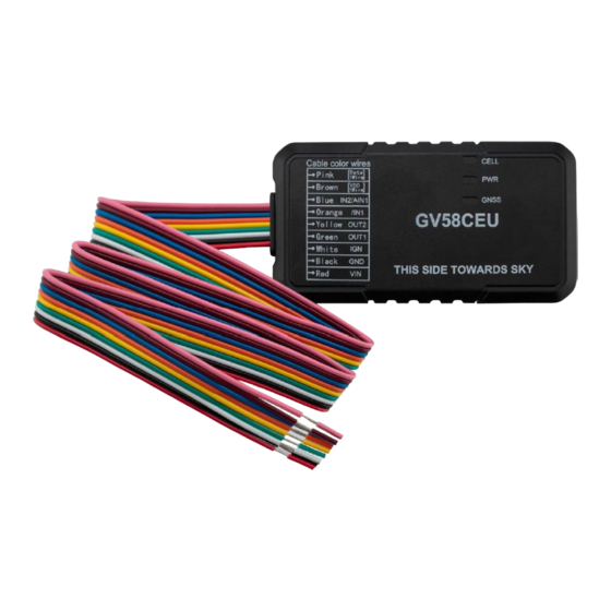
GV58CEU User Manual 2. Product Overview 2.1. Appearance Figure 1: Appearance of GV58CEU TRACGV58CEUUM001 – –... -
Page 9: Interface Definition
GV58CEU User Manual 2.2. Interface Definition GV58CEU has a 9-PIN interface connector. It contains the connections for power, and I/O. The sequence and definition of the 9-PIN connector are shown in the following figure: Figure 2: 9-PIN Wire Harness of GV58CEU... -
Page 10: Led Description
GV58CEU User Manual 2.3. LED Description GV58CEU has three status LEDs, which are CELL LED, PWR LED and GNSS LED. Table 4: LED Description Device Status LED Status GNSS GNSS chip is powered off. GNSS sends no data or data format error occurs. -
Page 11: Power Connection
GV58CEU User Manual 2.4. Power Connection VIN(Red) / GND(Black) are the power input pins. The input voltage range for this device is from 8V to 32V. The device is designed to be installed in vehicles that operate on 12V or 24V vehicle without the need for external transformers. -
Page 12: Digital Output
2.6. Digital Output There are two digital outputs on GV58CEU. All two digital outputs are of open drain type and the maximum drain current is 150mA. Figure 5: Digital Output Internal Drive Circuit... -
Page 13: Analog Input/Digital Input
GV58CEU User Manual 2.7. Analog Input/Digital Input There is one input can be configured as an analog input or a digital input on GV58CEU. analog input/ digital input For the , the range of input voltage is from 0V to 30V. -
Page 14: Get Started
GV58CEU User Manual 3. Get Started 3.1. Parts List Table 7: Parts List Name Picture GV58CEU Locator 86.7mm*46.4mm*18.1mm Data_Cable_M_V4 (Optional) TRACGV58CEUUM001 – –... -
Page 15: Gv58Ceu External Cable Interface
GV58CEU User Manual 3.2. GV58CEU External Cable Interface Table 8: GV58CEU User Cable Color Definition Definition Color PIN No Cable Data 1Wire Pink VDD 1Wire Brown IN2/AIN1 Blue /IN1 Orange OUT2 Yellow OUT1 Green White Black 3.3. Turn on/Turn off Turn on: Connect the device to external power, and it will be turned on automatically. -
Page 16: Open The Case
The GV58CEU device has 4 gaps. When GV58CEU is shipped, the case of GV58CEU is not closed completely, which allows the user to open it relatively easily for SIM card and battery installation. -
Page 17: Install A Sim Card
GV58CEU User Manual 3.5. Install a SIM Card Figure 10: SIM Card Installation Open the case and ensure the unit is not powered. Slide the holder up to open the SIM card holder. Insert the SIM card into the holder as shown above with the gold-colored contact area facing down. -
Page 18: Close The Case
GV58CEU User Manual 3.7. Close the Case Figure 12: Close the Case Put the upper cover on the lower cover, and press the covers to make sure they are closed completely. TRACGV58CEUUM001 – –... -
Page 19: Motion Sensor Direction
GV58CEU User Manual 3.8. Motion Sensor Direction GV58CEU has an internal 3-axis accelerometer supporting driving behavior monitoring, crash detection and motion detection. The following figure shows the directions of the motion sensor. Figure 13: Motion Sensor Direction Note: The opposite direction of the cable bundle is the positive direction of the X-axis. -
Page 20: Troubleshooting And Safety Information
Please do not put the device on overheated or too humid place, and avoid exposure to direct sunlight. Too high temperature will damage the device or even cause battery explosion. Please do not use GV58CEU on the airplane or near medical equipment. TRACGV58CEUUM001 –... - Page 21 FCC Warnings: This device complies with part 15 of the FCC Rules. Operation is subject to the following two conditions :(1)This device may not cause harmful interference, and (2)this device must accept any interference received, including interference that may cause undesired operation. ...
Need help?
Do you have a question about the GV58CEU and is the answer not in the manual?
Questions and answers