
Subscribe to Our Youtube Channel
Related Manuals for Queclink GL320M Series


Summary of Contents for Queclink GL320M Series
- Page 1 GL320M Series User Manual EGPRS/LTE Cat-M1/LTE Cat-NB2/GNSS Tracker QSZTRACGL320MUM0100 Version: 1.00...
- Page 2 QSZTRACGL320MUM0100 General Notes Queclink offers this information as a service to its customers, to support application and engineering efforts that use the products designed by Queclink. The information provided is based upon requirements specifically provided to Queclink by the customers. Queclink has not undertaken any independent search for additional relevant information, including any information that may be in the customer’s possession.
-
Page 3: Table Of Contents
GL320M Series User Manual Contents 0. Revision History ..........................1 1. Introduction ..........................2 1.1. GL320M Series Product ...................... 2 1.2. Reference ........................... 2 1.3. Terms and Abbreviations ....................2 2. Product Overview .......................... 3 2.1. Product Appearance ......................3 2.2. -
Page 4: Revision History
GL320M Series User Manual Revision History Version Date Author Description of Change 1.00 2021-04-06 Arry Wang Initial QSZTRACGL320MUM0100... -
Page 5: Introduction
GL320M Series User Manual Introduction The GL320M Series is water resistant GPS trackers designed for lone worker, vehicle, pet and asset tracking applications. The thumb sized button makes the series ideal for applications requiring rapid emergency alert or setting of Geo-fences based on current locations. The built-in GPS receiver has superior sensitivity and fast initial positioning. -
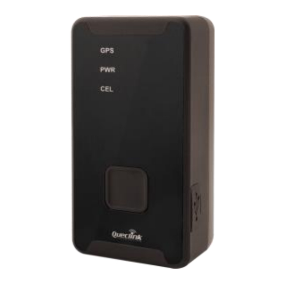
Page 6: Product Overview
GL320M Series User Manual Product Overview 2.1. Product Appearance Power Key LEDs Type-C SIM Card Holder Function Key Figure 1. GL320M Product View 2.2. Key/Type-C Interface Description Table 4. GL320M Button/Mini USB Interface Description ⚫ Turn on GL320M ⚫ Power Key Turn off GL320M when it is not being charged (if the power key is enabled). -
Page 7: Led Description
Fast flash Power low alert Slow flash The power light is turned off by command. Dark <LED On> is set to 2. Dark Note: Please refer to GL320M Series @Track Air Interface Protocol for the settings of <LED On>. QSZTRACGL320MUM0100... -
Page 8: Parts List
GL320M Series User Manual 2.4. Parts List Table 6. GL320M Parts Lists Name Picture Description EGPRS/LTE Cat-M1/LTE GL320M Locater Cat-NB2/GNSS Tracker AC-DC Power Adapter Used to charge the internal (standard battery of GL320M accessory) AC-DC Power Adapter (fast Used to charge the internal... -
Page 9: Interface Definition
GL320M Series User Manual Interface Definition The GL320M has a 12-pin (two sides) Type-C interface which contains the connections for power, ignition detection, input, etc. The sequence and definition of the 24-pin connector are shown in the following figure: Figure 3. 12-pin (two sides) Type-C Interface of the GL320M Table 7. -
Page 10: Gl320M Device Cable Color (Optional Extension Cable)
GL320M Series User Manual GL320M Device Cable Color (Optional Extension Cable) GL320M Extension Cable has a Type-C connector with six wires which allows the connection to the external power interface, ignition detection interface and input interface for GL320M. Please find the details in the following table. -
Page 11: Getting Started
GL320M Series User Manual Getting Started 5.1. Battery Charging Connect AC-DC power adapter to GL320M. Insert the AC-DC power adapter into the power socket. During charging, the PWR LED flashes fast. When the battery is fully charged, the PWR LED will be always on. -
Page 12: External Power Supply Connection
GL320M Series User Manual 5.3. External Power Supply Connection 5.3.1. External DC Charger Connection Pin 4 and Pin 9 on the Type-C connector is used for charging and named as VBUS pins. It can be connected to a 5V DC power supply to power up GL320M and charge the internal battery. -
Page 13: Ignition Detection
GL320M Series User Manual 5.4. Ignition Detection Pin 3 on the Type-C connector is for ignition detection when GL320M is used in vehicle tracking application. It is named as IGN_INPUT pin. Figure 7. Ignition Detection Connection of GL320M Another easy way is to connect PIN3 to a power output which is only enabled when the vehicle is ignition on (e.g. -
Page 14: External Input Connection
GL320M Series User Manual 5.5. External Input Connection Pin 2 on the Type-C USB connector is a negative trigger input. It is named as IN1 pin. For negative trigger input, the electrical characteristics are: Logic State Electrical Characteristics Active 0V to 0.8V Inactive 1.7V to 32V or Open loop... -
Page 15: Installation Precautions
GL320M Series User Manual Installation Precautions ◆ Firmly install the device to a reliable surface to prevent falling off. ◆ Make the side with antenna face sky to have better signal reception. ◆ Do not install the device under metal surface or in enclosed environments having difficulty in getting GPS and network signal. -
Page 16: Troubleshooting And Safety Info
GL320M Series User Manual Troubleshooting and Safety Info 7.1. Troubleshooting Table 8. GL320M Troubleshooting List Trouble Possible Reason Solution After the device is turned The signal is too weak. The Move the device to a place with on, the CEL LED always device isn’t registered to the... -
Page 17: Appendix: Supported Accessories
GL320M Series User Manual Appendix: Supported Accessories ◆ External large volume battery pack QSZTRACGL320MUM0100...
Need help?
Do you have a question about the GL320M Series and is the answer not in the manual?
Questions and answers
It keeps telling me Unit Offline, how do I remedy that?
To fix the "Unit Offline" issue on the Queclink GL320M Series, follow these steps based on similar troubleshooting for the GV75MG:
1. Check Signal Strength: Move the device to an area with good network coverage. A weak signal can prevent network registration.
2. Verify Network Registration: If the CEL LED flashes quickly, the device is not registered to the network. Ensure the SIM card is active and inserted correctly.
3. Check APN Settings: Incorrect APN settings can prevent communication with the backend server. Confirm and set the correct APN for your network provider.
4. Proper Installation: Ensure the device is not installed under a metal surface or in an enclosed area that blocks GPS and network signals.
If the issue persists after these checks, further diagnostics may be required.
This answer is automatically generated