Table of Contents
Advertisement
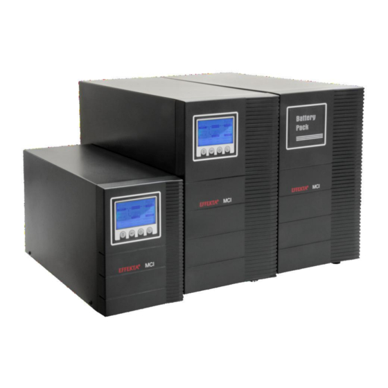
Uninterruptible Power Supply
MCI- Series 700, 1000, 2000, 3000 VA
(including the XL variants)
Online Double Converter, TOWER Format
Operating Manual V 2.1
Article Number:
Translation of the original Operating Manual
ACX11CIS70000000
ACX11CIS1K000000
ACX11CIS2K000000
ACX11CIS3K000000
ACX11CIS70000SXL
ACX11CIS1K000SXL
ACX11CIS2K000SXL
ACX11CIS3K000SXL
Advertisement
Chapters
Table of Contents
Troubleshooting

Subscribe to Our Youtube Channel
Related Manuals for Effekta ACX11CIS70000000


Summary of Contents for Effekta ACX11CIS70000000
- Page 1 Uninterruptible Power Supply MCI- Series 700, 1000, 2000, 3000 VA (including the XL variants) Online Double Converter, TOWER Format Operating Manual V 2.1 Article Number: ACX11CIS70000000 ACX11CIS1K000000 ACX11CIS2K000000 ACX11CIS3K000000 ACX11CIS70000SXL ACX11CIS1K000SXL ACX11CIS2K000SXL ACX11CIS3K000SXL Translation of the original Operating Manual...
- Page 2 MCI 700, 1000, 2000, 3000 VA (XL) Legal notice Legal notice by EFFEKTA Regeltechnik GmbH This documentation is solely intended for the operator and his staff. The content of this documentation (texts, figures, drawings, graphics, plans, etc.) may not be...
-
Page 3: Table Of Contents
MCI 700, 1000, 2000, 3000 VA (XL) Table of contents Table of contents Introduction ......................5 Preface ........................5 Validity ........................6 Storage ........................6 Abbreviations, Terms and Symbols................6 Information Obligation ....................9 Warranty Conditions ....................10 Limitation of Liability ....................11 Safety Instructions .................... - Page 4 MCI 700, 1000, 2000, 3000 VA (XL) Table of contents Signals, Error Codes and Troubleshooting Measures ........49 Troubleshooting ....................52 Service-Hotline....................... 52 Software ......................... 53 Maintenance and Service ..................54 12.1 Measuring Back-up Time (Autonomy Period) ............54 12.2 Replacing Components / Accumulators ..............55 12.3 Maintenance and Service Contracts ................
-
Page 5: Introduction
Please read this operating manual carefully and take note particularly of the safety instructions! If you have questions about the device, the technical supervisor in your com- pany or our employees will gladly assist you. Your EFFEKTA Regeltechnik GmbH MCI series... -
Page 6: Validity
(UPS) defined in the technical data as a whole or as it refers to modules, components and individual parts that were developed and built by EFFEKTA Regeltechnik GmbH ( Chapter13. Technical Data). Read this documentation carefully and familiarize yourself with the product before you start operating it. - Page 7 MCI 700, 1000, 2000, 3000 VA (XL) Introduction Text that is marked with WARNING! provides a warning about hazards. If ac- cident prevention measures are not taken, these dangers may result in seri- ous (irreversible) injuries or even death! Text that is marked with CAUTION! provides a warning about hazards. If acci- dent prevention measures are not taken, these dangerous situations can lead to slight or medium reversible injuries.
- Page 8 MCI 700, 1000, 2000, 3000 VA (XL) Introduction Specific warning: Warning about dangerous electrical voltage! Warning about proper handling of accumulators! Instruction symbols: Take note of the provided documentation(s) and/or instructions! Disconnect prior to additional work! Environment protection symbols: Identifies instructions for recycling. Identifies components that are subject to the Electronic Scrap Regulation.
-
Page 9: Information Obligation
This applies in particular to maintenance, operating and cleaning personnel including persons responsible for transportation and/or disposal. EFFEKTA Regeltechnik GmbH is not liable for damage incurred or caused by staff who have not been trained or who have been insufficiently trained! -
Page 10: Warranty Conditions
MCI 700, 1000, 2000, 3000 VA (XL) Introduction Warranty Conditions The receipt of delivery is considered as the record for the initial purchase and should be kept in a safe place. It will be necessary for making any warranty claims. If the product is passed on to another user, that user has the right to make warranty claims for the remainder of the warranty period. -
Page 11: Limitation Of Liability
EFFEKTA Regeltechnik GmbH was informed about the possibility of such damage in advance. This exemption also includes any liability that can result from the claims of third parties against the initial purchaser. -
Page 12: Safety Instructions
MCI 700, 1000, 2000, 3000 VA (XL) Safety Instructions Safety Instructions Introduction The UPS is a device that has been produced according to the rules and regula- tions of technology for an uninterruptible power supply. The device is safe when used properly and under consideration of the safety re- quirements and instructions provided in this operating manual. -
Page 13: Avoiding Personal Injuries / Property Damage
Follow the instructions steps as specified. Only use original replacement parts from EFFEKTA Regeltechnik GmbH Protecting the Environment Send the product back to EFFEKTA Regeltechnik GmbH after the end of its service life. We will ensure environmentally responsible disposal. Transport and Storage The UPS may only be transported to the intended location in the original pack- aging. -
Page 14: Positioning
MCI 700, 1000, 2000, 3000 VA (XL) Safety Instructions Positioning Only operate the UPS in well ventilated rooms, within the specified ambient tem- perature range (according to 13 Technical Data). The UPS may not be placed in the vicinity of heat sources. Always take the operating position into account when positioning the device. -
Page 15: Operation
MCI 700, 1000, 2000, 3000 VA (XL) Safety Instructions – Install all connections appropriately and keep the cable length as short as possible; – Only use suitable power cables for the connection of the UPS with the electricity grid and ensure the required current carrying capacity; –... -
Page 16: Maintenance, Service And Malfunctions
MCI 700, 1000, 2000, 3000 VA (XL) Safety Instructions Accumulators and their circuit points can cause electric shocks. In the event of a short-circuit of the accumulators, touching the current-carrying parts can result in severe burns. Do not place accumulators in the vicinity of heat sources and do not bring them in contact with open fire. - Page 17 MCI 700, 1000, 2000, 3000 VA (XL) Safety Instructions The following aspects have to be considered, when carrying out work on the UPS or the accumulators: – Before you begin any work on the UPS, it must be switched of and disconnected from the power grid and from all the appliances.
-
Page 18: Ups Device Description
MCI 700, 1000, 2000, 3000 VA (XL) Device Description UPS Device Description This UPS-unit is an ONLINE-UPS according to the double conversion principle. The UPS receives the classification "Class 1 (VFI-SS-111) due to the excellent operating performance pursuant to EN62040-4. Consequently, any appliances connected via the unit can be ideally supplied, regardless of the performance of the primary energy source (mains power supply). - Page 19 MCI 700, 1000, 2000, 3000 VA (XL) Device Description Normal operating mode (INVERTER-MODE) The normal operating mode is characterized here by the typical double conver- sion. The mains power supply is converted into the DC intermediate circuit, which in turn feeds the UPS output via the inverter (DC/AC converter). In this mode, the BYPASS is inactive.
- Page 20 MCI 700, 1000, 2000, 3000 VA (XL) Device Description UPS mains power supply output input Fig. 3-4 Operating mode: Static BYPASS. Do not leave the UPS in static by-pass mode or fault mode for any extended pe- riod of time. Even though the appliances continue to be supplied, no backup support function is provided by the UPS.
-
Page 21: The Device Series, Format And Casing Dimensions
The MCI series is produced in several performance variations including an XL model for each variant. See the following table: Capacity Description Article number: Casing: Note: [VA] MCI-700 standard ACX11CIS70000000 MCI-1000 1000 standard ACX11CIS1K000000 MCI-2000 2000 standard ACX11CIS1K000000 MCI-3000 3000... -
Page 22: The Usp And Its Components In Detail
MCI 700, 1000, 2000, 3000 VA (XL) Device Description The UPS and its components in detail All components for the operation of the device are located in the font and all components for its connection or the installation are located at the back of the device (see Fig. - Page 23 MCI 700, 1000, 2000, 3000 VA (XL) Device Description MCI 3000 MCI 3000 XL (1) EPO port; (7) Load port (UPS output); (2) USB-port; (7b) Load port (16 Ampere); (3) RS232 port; (8) Fuse(s) load port; ...
- Page 24 MCI 700, 1000, 2000, 3000 VA (XL) Device Description 3.3.2 The port area, back side of the UPS The Figure shows the UPS input (6, mains IEC connector) and an input circuit breaker (5). The connection is labeled as "AC INPUT" and can dif- fer between the individual models.
- Page 25 MCI 700, 1000, 2000, 3000 VA (XL) Device Description 3.3.3 Specification plate of the equipment On the specification plate of the UPS you will find the following information, among others: the model name; information regarding supply data; article number;...
- Page 26 MCI 700, 1000, 2000, 3000 VA (XL) Device Description LCD Display ON button Select or buzzer off Enter OFF button Keypad and Control Panel: Selection key (SELECT): by pressing this key, the selection (blinking of the item) scrolls through the list of parameters. Enter key (ENTER): by pressing this key you can confirm a selection that had previously been se- lected with the selection key.
-
Page 27: Bypass Mode
MCI 700, 1000, 2000, 3000 VA (XL) Device Description 3.3.1.1 DISPLAY information of the control panel The Status and other information regarding the device can be read from the control panel, or the LC display respectively, and important parameters can be set there. -
Page 28: Normal Operating Mode
MCI 700, 1000, 2000, 3000 VA (XL) Device Description Load data (UPS output): The output load is displayed as percentage rela- tive to the max. possible power output. The unit in W (watt) or VA is displayed which is predomi- nates at that moment. -
Page 29: Storage And Unpacking
MCI 700, 1000, 2000, 3000 VA (XL) Storage and Unpacking Storage and Unpacking Storage of the UPS If the UPS or the accumulator bank are to be put into storage after delivery, the following aspects should absolutely be adhered to: Always leave the UPS and its accessories in the original packaging;... -
Page 30: Unpacking And Positioning Of The Usp
MCI 700, 1000, 2000, 3000 VA (XL) Storage and Unpacking Unpacking and positioning of the UPS At the installation site, the utmost care shall be taken when removing the pack- aging in order to avoid damage to the equipment or the packing material as far as possible. -
Page 31: Installation And Connection Of The Usp
MCI 700, 1000, 2000, 3000 VA (XL) Installation and Connection UPS Installation and Connection All thresholds listed in the technical specifications regarding ambient and oper- ating conditions must be met, to ensure proper operation of the UPS. The system may only be installed and connected by trained authorized electri- cians in accordance with relevant safety rules, applicable standards, and na- tional regulations! The UPS must be installed in a well-ventilated environment, far away from liq-... -
Page 32: External Bypass
MCI 700, 1000, 2000, 3000 VA (XL) Installation and Connection Fig. 5-1 Possible installation and mounting positions for the MCI series. Fig. 5-2 Arrangement of a combined equipment (accumulator bank and UPS, here MCI 3000) In general, please always ensure that the threshold values listed in the 13 Technical Data are observed. -
Page 33: Preparing Linkups
Always make sure that the UPS and the accumulator bank are compatible. Suit- able products are being tested by EFFEKTA Regeltechnik GmbH and listed in 14 Scope of delivery/ Accessories. The same holds true for accumulator bank connection cables, which is also tested in the same way and listed in 14 Scope of delivery/ Accessories. -
Page 34: Connection Of The Usp
MCI 700, 1000, 2000, 3000 VA (XL) Installation and Connection 5.2.2 Final inspections and safety measures Please follow the safety precautions ( 2.7 Connection) for all components to be connected, including the mains power supply, before you begin with the connection procedure. - Page 35 MCI 700, 1000, 2000, 3000 VA (XL) Installation and Connection You should always make sure that the wall socket is properly fused and that a protective earth conductor connection is established. Furthermore, the load/s can in general be connected to the UPS with a corre- sponding power cord.
- Page 36 MCI 700, 1000, 2000, 3000 VA (XL) Installation and Connection Device: Conductor Circuit breaker Outlet con- cross-sec- (S): nection: tion(1): MCI 700, 1000 (XL) 1.5 mm² 10 A ( > 7 A) 3x IEC C13 MCI 2000 (XL) 2.5 mm² 20 A ( >...
- Page 37 MCI 700, 1000, 2000, 3000 VA (XL) Installation and Connection If you open the end caps, all subsequent steps will be carried out on a live sys- tem. For this, all safety measures must be observed. Please make sure before- hand, that the supply data of both devices match.
- Page 38 MCI 700, 1000, 2000, 3000 VA (XL) Installation and Connection Pin Sub-D: Description: Function: Send (output) Receive (input) 5.3.3 EPO connector (EMERGENCY POWER OFF), dropping of loads The EPO can be used as an external emergency/off function. EPO, emergency/off contact: Use the supplied double-pole plug for this and connect one opener contact to it (e.g.
-
Page 39: Operation
MCI 700, 1000, 2000, 3000 VA (XL) Operation Operation Due to the extensive protective functions the device performs in relation to the appliance/s, the UPS operates almost automatically. The operational control of the device / equipment is thus limited to only a few steps which is in addition to the limitation of authority. - Page 40 MCI 700, 1000, 2000, 3000 VA (XL) Operation 6.1.1 Switching the UPS on and starting of the equipment Switching into STANDBY mode and starting the UPS equipment is performed by way of the following procedure. Always follow the steps in the order de- scribed here: •...
-
Page 41: Autonomous Mode
MCI 700, 1000, 2000, 3000 VA (XL) Operation 6.1.2 Turning-off the UPS The following procedure lists the necessary steps switch off the UPS. Always follow the steps in the order described here: ✓ The initial state of the equipment is normal operating mode! •... - Page 42 MCI 700, 1000, 2000, 3000 VA (XL) Operation Often, a forced switch to autonomous mode is performed on purpose to text the duration of the autonomous period (backup time) or the UPS equipment. 6.1.4 Direct switching to autonomous mode (COLD START) Even if no connection to the mains power supply is established, the UPS can be switched directly into autonomous mode.
-
Page 43: Test Mode
MCI 700, 1000, 2000, 3000 VA (XL) Operation A COLD START, also called BLACK START, is frequently used to perform some load or static load tests with connected appliances in advance. While do- ing so, always monitor the load display (LOAD) on the control unit. Do not leave the device / equipment in this state. -
Page 44: Warning Signals Of The Ups
MCI 700, 1000, 2000, 3000 VA (XL) Operation 6.1.7 Warning signals of the UPS If the UPS reaches a state of overload, e.g. due to load behavior, it emits a warning signal in the form of a status display and an acoustic signal. The UPS reports the issue by dis- playing a WARNING-CODE (here 29). -
Page 45: Ups Settings
MCI 700, 1000, 2000, 3000 VA (XL) Operation UPS settings In general, all settings relevant to the UPS are set via the UPS control panel. These include first and foremost: Settings regarding the initial configuration of the UPS; Turning the BYPASS mode on and off;... - Page 46 MCI 700, 1000, 2000, 3000 VA (XL) Operation The following illustration additionally depicts the path of the CURSOR by hitting the selection key through the individual parameters of the UPS. Below, several settings are listed as examples: Setting of output voltage of 230: ✓...
- Page 47 MCI 700, 1000, 2000, 3000 VA (XL) Operation After starting the UPS it will only switch to ECO mode very slowly (approx. 20 s), as several tests are run internally. Please have patience. Setting the operating mode "BYPASS": ✓ The starting position for the equipment is STANDBY mode! •...
-
Page 48: Commissioning Of The Ups
UPS: MPR 2000 (RACKMOUNT) Commissioning Commissioning of the UPS The commissioning is premised on the condition that all previous chapters of this manual have already been successfully implemented and inspected. In addition, check whether all connected loads are and turned off. The commis- sioning of the UPS equipment may only be performed by accredited service per- sonnel. -
Page 49: Signals, Error Codes And Troubleshooting Measures
MCI 700, 1000, 2000, 3000 VA (XL) Error messages Signals, Error Codes and Trouble- shooting Measures Status messages of the UPS The following list shows the status messages of the individual operating modes of the UPS in a table: Reporting number Additional Operating mode: (MODE):... -
Page 50: Warning 10
MCI 700, 1000, 2000, 3000 VA (XL) Error messages Error messages of the UPS The following list shows the error messages of the individual operating modes of the UPS in a table: Report number Additional Error status: (FAULT): symbols: Internal Bus fault INVERTER error Overload at output Over temperature error... -
Page 51: High
MCI 700, 1000, 2000, 3000 VA (XL) Error messages In this case, the UPS automatically The accumulator The end of charging volt- switches to autonomous mode to dis- bank voltage too age of the accumulator charge the accumulator bank and high bank is too high. -
Page 52: Troubleshooting
0049 / (0) 741 – 17451-52 Phone: 0049 / (0) 741 – 17451-29 Fax: You can also reach us via e-mail at: kundendienst@effekta.com In addition you can contact the central area or branch office directly as listed on our website: http://www.effekta.com MCI series... -
Page 53: Software
UPS: MPR 2000 (RACKMOUNT) Software Software The UPS management software runs as a client / server application for hetero- geneous networks or on a local computer. It works on any common platform (Win, Linux, UNIX). Remote access to the UPS and its data is possible and can be logged. The software shows all relevant UPS data like accumulator condition, tempera- ture, condition of the mains power supply, among others in a clear and simple graphic interface. -
Page 54: Maintenance And Service
MCI 700, 1000, 2000, 3000 VA (XL) Maintenance and Service Maintenance and Service You may expect a long service life and interference-free operation of your UPS. However, the service life and reliability of the UPS is greatly dependent on the ambient conditions. -
Page 55: Replacing Components / Accumulators
(key word: dust). 12.2 Replacing components / accumulators Only EFFEKTA Regeltechnik service personnel or personnel of other accredited service points is authorized to replace accumulators in the UPS or in an external accumulator bank, as well as other UPS components. -
Page 56: Maintenance And Service Contracts
12.3 Maintenance and service contracts EFFEKTA Regeltechnik GmbH also offers the related maintenance services to ensure the highest possible reliability and availability of the UPS. In addition, we offer maintenance contracts to support and assist you in the following areas with... -
Page 57: Service Log
MCI 700, 1000, 2000, 3000 VA (XL) Maintenance and Service 12.4 Service-Log Please always enter all maintenance and service work conducted on the UPS equipment into the service-log. Date Performed tasks Performed by MCI series... -
Page 58: Technical Data
MCI 700, 1000, 2000, 3000 VA (XL) Technical Data Technical Data MCI: 700 (XL) 1000 (XL) 2000 (XL) 3000 (XL) UPS input: Connection 1 phase, neutral and protective earth Voltage range 110 - 300 VAC BYPASS range 110 - 276 VAC Frequency range 45~55 Hz, 54~66 Hz (50/60 Hz automatic detection) Input current... -
Page 59: Typical Autonomy Periods
MCI 700, 1000, 2000, 3000 VA (XL) Technical Data Device protection Overload, total discharge, over-charging Measurements W x D x 145x400x220 145x400x220 192x460x347 192x460x347 H [mm] Weight [kg] UPS category VFI-SS-111 Device protection class IP20 Integrated communica- RS232, USB (not simultaneously usable) tion Communication (option) Intelligent interface cards: SNMP, contact interface... -
Page 60: Scope Of Delivery/ Accessories
MCI 700, 1000, 2000, 3000 VA (XL) Accessories Scope of delivery/ Accessories Below you find the list of the scope of delivery, please check your delivery for completeness. Please let us know immediately, should any items or compo- nents be missing in your delivery. Number Article or Article No. -
Page 61: Optional Accessories
MCI 700, 1000, 2000, 3000 VA (XL) Accessories Optional accessories The components, devices and/or equipment listed below are accessories that fit the MCI series and that have been tested and approved by EFFEKTA Regel- technik GmbH. 15.1 External accumulator bank and connection cable Every UPS system requires an energy storage to supply the stored power to the loads during a power failure. -
Page 62: Communikation Adapter Snmp
MCI 700, 1000, 2000, 3000 VA (XL) Accessories Fig. 15-1 UPS mode Fig. 15-2 BYPASS mode In this case, maintenance and service tasks of the UPS or the accumulator bank can be performed in a fast and safe manner. On rare occasions, the UPS or its components can also be replaced without in- terruption of the loads. -
Page 63: Communikation Adapter, Relay Card (As400)
MCI 700, 1000, 2000, 3000 VA (XL) Accessories For additional information about this product and the associated software please contact our sales and service centers. 15.4 Communication adapter, relay card (Z0C/AS400) The relay card is also an intelligent extension card and is used for the direct and floating coupling with external controls and/or machines. -
Page 64: Wearing Parts List
All units labeled with a CE sign fulfill the EU harmonized standards and regula- tions. The EU-declaration of conformity for this product is available upon request. Please contact our 10 Service hot-line. You can also find the declaration of conformity for this product on our website: http://www.effekta.com MCI series... - Page 65 MCI 700, 1000, 2000, 3000 VA (XL) Notes MCI series...
- Page 66 MCI 700, 1000, 2000, 3000 VA (XL) Notes MCI series...
- Page 67 MCI 700, 1000, 2000, 3000 VA (XL) Notes MCI series...
- Page 68 MCI 700, 1000, 2000, 3000 VA (XL) Notes EFFEKTA Regeltechnik GmbH Rheinwaldstraße 34 D – 78628 Rottweil/Germany MCI series...
Need help?
Do you have a question about the ACX11CIS70000000 and is the answer not in the manual?
Questions and answers