Table of Contents
Advertisement
Advertisement
Table of Contents

Subscribe to Our Youtube Channel
Related Manuals for Matrix 7XE


Summary of Contents for Matrix 7XE
- Page 1 2 0 1 6 7 x e / 7 x i c o n s o l e s e R V i c e M A n U A l...
-
Page 2: Table Of Contents
Working Environment Set Up for Parts Replacement..........41 T7xe UCB Replacement ..................... 42 T7xe TFT-LCD Module Replacement ................. 43 7xe UCB REPLACEMENT ..................44 7xe TFT-LCD Module Replacement ................45 T7xi UCB Module Replacement .................. 46 T7xi TFT-LCD Module Replacement ................47 7xi UCB REPLACEMENT ................... 48 7xi TFT-LCD Module Replacement ................ -
Page 3: Chapter 1: Serial Number Location
1: seRiAl nUMbeR locATion 1.1 seRiAl nUMbeR locATion console serial number location 7xe / 7xi T7xe / T7xi... -
Page 4: Electrical Requirements
An external power supply will ensure power is provided to the console at all times and is recommended when add-on accessories are used. For units with an integrated TV (like the 7xe and 7xi), the TV power requirements are included in the unit. An RG6 coaxial cable with ‘F Type’... -
Page 5: Chapter 3: Preventive Maintenance
3.2 cHecK foR DAMAgeD PARTs Do noT use any equipment that is damaged or has worn or broken parts. Use only replacement parts supplied by Matrix Fitness Systems. MAinTAin lAbels AnD nAMePlATes. Do not remove labels for any reason. They contain important information. If unreadable or missing, contact Matrix Fitness Systems for a replacement. -
Page 6: Chapter 4: Console Overlay And Workout Description
A7xe console sHoWn 7xe console DescRiPTion The Matrix machine is inspected before it is packaged. It is shipped in two pieces: the base and the console. Carefully unpack the unit and dispose of the box material. Note: There is a thin protective sheet of clear plastic on the overlay of the console that should be removed before use. - Page 7 T7xe console sHoWn T7xe console DescRiPTion The Matrix machine is inspected before it is packaged. It is shipped in two pieces: the base and the console. Carefully unpack the unit and dispose of the box material. Note: There is a thin protective sheet of clear plastic on the overlay of the console that should be removed before use.
- Page 8 7xi console DescRiPTion e.g. A7xi console sHoWn The Matrix machine is inspected before it is packaged. It is shipped in two pieces: the base and the console. Carefully unpack the unit and dispose of the box material. Note: There is a thin protective sheet of clear plastic on the overlay of the console that should be removed before use.
- Page 9 T7xi console sHoWn T7xi console DescRiPTion The Matrix machine is inspected before it is packaged. It is shipped in two pieces: the base and the console. Carefully unpack the unit and dispose of the box material. Note: There is a thin protective sheet of clear plastic on the overlay of the console that should be removed before use.
-
Page 10: 7Xe/7Xi Console Operation
4: console oVeRlAy AnD WoRKoUT DescRiPTion 4.2 7xe/7xi console oPeRATion 7xe/7xi console oPeRATion geTTing sTARTeD login scReen • Touch the UseR button to sign-in with your XID. • Touch the gUesT button to work out anonymously. • Touch the RegisTeR button to create a new XID. - Page 11 4: console oVeRlAy AnD WoRKoUT DescRiPTion 4.2 7xe/7xi console oPeRATion - conTinUeD go scReen PRogRAM seTUP note: Workouts and features vary based on model type, console configurations, software versions and options purchased.
- Page 12 4: console oVeRlAy AnD WoRKoUT DescRiPTion 4.2 7xe/7xi console oPeRATion - conTinUeD HoMescReen HoMescReen • The UseRnAMe or gUesT is shown in the upper left corner. • Touch to change WoRKoUT sTATisTics displayed at the bottom of the screen.
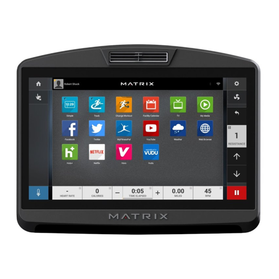
- Page 13 4: console oVeRlAy AnD WoRKoUT DescRiPTion 4.2 7xe/7xi console oPeRATion - conTinUeD APPs AnD enTeRTAinMenT siMPle WeATHeR Workout stats are displayed in Get local weather info. 3 customizeable windows. TRAcK Web bRoWseR Displays a 400 (1/4 ) track. Split...
- Page 14 4: console oVeRlAy AnD WoRKoUT DescRiPTion 4.2 7xe/7xi console oPeRATion - conTinUeD fiRsT TiMe seTUP scReens To enter "Restore Factory Defaults" setting, press "ENTER, 3, 0, 0, 2, ENTER" on the number keypad and Factory Defaults setting will appear on the display.
- Page 15 4: console oVeRlAy AnD WoRKoUT DescRiPTion 4.2 7xe/7xi console oPeRATion - conTinUeD noTe: This equipment has been tested and found to comply with the limits for a Class B digital device, pursuant to part 15 of the FCC rules.
-
Page 16: Chapter 5: Manager Mode
cHAPTeR 5: MAnAgeR MoDe 5.1 Using MAnAgeR MoDe 1) To enter Manager Mode, press "ENTER, 1, 0, 0, 1, ENTER" on the number keypad and Manager Mode will appear on the display. 2) Manager Mode is divided into 9 tabs, located on the left side of the screen. They are General, Workout, Setup Defaults, Network Setup, Asset Management, Weather, TV, Applications, Hardware and Service. -
Page 17: Manager Mode Overview
TACSEHUR Firmware Versions TACSEHUR Language Setup TACSEHUR English (U.S.) See Languages Table “I just exercised for Social Network Post TACSEHUR [time] on a Matrix Fitness 7xi” Keyboard Disable Machine Minimum - 2.0MPH/3.2KPH MPH/KPH Threshold 4.0MPH/6.4KPH Maximum Workout Time TACSEHUR 10-120... - Page 18 cHAPTeR 5: MAnAgeR MoDe 5.2 MAnAgeR MoDe oVeRVieW Category Name Models Default Range Units Level TASEHUR (TSEHUR)1-20 (A)1-25 TACSEHUR 10-99 Years (THUR)50-400lbs/22-182kg Weight TACSEHUR 150lbs/68kg (AE)44-440lbs/20-200kg lbs/kg (CS) 80-400lbs/36-182kg Height 70in/173cm 40-90in/101-228cm in/cm Gender TACSEHUR Male Male/Female Setup Default Default Workout Time TACSEHUR 5-Max Minutes...
- Page 19 cHAPTeR 5: MAnAgeR MoDe 5.2 MAnAgeR MoDe oVeRVieW - conTinUeD Category Name Models Default Range Units Weather Enable Alerts TACSEHUR Check Check/No Check Tuner Type TACSEHUR Main Main, Brazil, Japan Connection Type TACSEHUR Antenna Antenna/Cable Country TACSEHUR United States Countries Source TACSEHUR ATSC...
- Page 20 cHAPTeR 5: MAnAgeR MoDe 5.2 MAnAgeR MoDe oVeRVieW - conTinUeD Category Name Models Default Range Units Default TV Channel TACSEHUR Channels View input on mini TV Channel Setup TACSEHUR Up, Down, Confirm screen. Default TV Channel TACSEHUR Channels TV(Pro:ldiom) Tuner Type TACSEHUR CVBS HDMI / CVBS...
-
Page 21: Chapter 6: Engineering Mode
cHAPTeR 6: engineeRing MoDe 6.1 Using engineeRing MoDe 1) To enter Engineering Mode, press "ENTER, 2, 0, 0, 1, ENTER" on the number keypad and Manager Mode will appear on the display. 2) Engineering Mode is divided into 9 tabs, located on the left side of the screen. They are General, Workout, Setup Defaults, Update, Network Setup, Asset Management, Weather, TV, Applications, Calibration, Hardware, Service and Errors. -
Page 22: Engineering Mode Overview
Show Setup Wizard TACSEHUR Check Yes/No Language Setup TACSEHUR English (U.S.) See Languages Table “I just exercised for Social Network Post TACSEHUR [time] on a Matrix Fitness 7xi” Dapi Environment TACSEHUR Production Keyboard Disable Machine Minimum - 2.0MPH/3.2KPH MPH/KPH Threshold 4.0MPH/6.4KPH... - Page 23 cHAPTeR 6: engineeRing MoDe 6.2 engineeRing MoDe oVeRVieW - conTinUeD Category Name Models Default Range Units Level TASEHUR (TSEHUR)1-20 (A)1-25 TACSEHUR 10-99 Years (THUR)50-400lbs/22-182kg Weight TACSEHUR 150lbs/68kg (AE)44-440lbs/20-200kg lbs/kg (CS) 80-400lbs/36-182kg Height 70in/173cm 40-90in/101-228cm in/cm Gender TACSEHUR Male Male/Female Setup Default Default Workout Time TACSEHUR 5-Max...
- Page 24 cHAPTeR 6: engineeRing MoDe 6.2 engineeRing MoDe oVeRVieW - conTinUeD Category Name Models Default Range Units Weather Enable Alerts TACSEHUR Check Check/No Check Tuner Type TACSEHUR Main Main, Brazil, Japan Connection Type TACSEHUR Antenna Antenna/Cable Country TACSEHUR United States Countries Source TACSEHUR ATSC...
- Page 25 cHAPTeR 6: engineeRing MoDe 6.2 engineeRing MoDe oVeRVieW - conTinUeD Category Name Models Default Range Units Default TV Channel TACSEHUR Channels View input on mini TV Channel Setup TACSEHUR Up, Down, Confirm screen. Default TV Channel TACSEHUR Channels TV(Pro:ldiom) Tuner Type TACSEHUR CVBS HDMI / CVBS...
-
Page 26: Using Service Mode
cHAPTeR 7: seRVice MoDe 7.1 Using seRVice MoDe 1) To enter Service Mode, press "ENTER, 3, 0, 0, 1, ENTER" on the number keypad and Service Mode will appear on the display. 2) Service Mode is divided into 9 tabs, located on the left side of the screen. They are General, Workout, Setup Defaults, Network Setup, Asset Management, Weather, TV, Applications, Hardware and Service. -
Page 27: Service Mode Overview
Show Setup Wizard TACSEHUR Yes/No Language Setup TACSEHUR English (U.S.) See Languages Table “I just exercised for Social Network Post TACSEHUR [time] on a Matrix Fitness 7xi” Keyboard Disable Machine Minimum - 2.0MPH/3.2KPH MPH/KPH Threshold 4.0MPH/6.4KPH Maximum Workout TACSEHUR 10-120... - Page 28 cHAPTeR 7: seRVice MoDe 7.2 seRVice MoDe oVeRVieW - conTinUeD Category Name Models Default Range Units Level TASEHUR (TSEHUR) 1-20 (A)1-25 TACSEHUR 10-99 Years (THUR) 50-400lbs/22-182kg Weight TACSEHUR 150lbs/68kg (AE) 44-440lbs/20-200kg lbs/kg (CS) 80-400lbs/36-182kg Height 70in/173cm 40-90in/101-228cm in/cm Gender TACSEHUR Male Male/Female Default Workout Time...
- Page 29 cHAPTeR 7: seRVice MoDe 7.2 seRVice MoDe oVeRVieW - conTinUeD Category Name Models Default Range Units Weather Enable Alerts TACSEHUR Check Check/No Check Tuner Type TACSEHUR Main Main, Brazil, Japan Connection Type TACSEHUR Antenna Antenna/Cable Location TACSEHUR United States Countries Source TACSEHUR ATSC...
- Page 30 cHAPTeR 7: seRVice MoDe 7.2 seRVice MoDe oVeRVieW - conTinUeD Category Name Models Default Range Units Default TV Channel TACSEHUR Channels TV(Pro:ldiom) Tuner Type TACSEHUR CVBS HDMI/CVBS Applications Application Setup TACSEHUR Show Key test TACSEHUR Calibration Calibration Calibrate Calibrate Run machine TACSEHUR RFID Module TACSEHUR...
-
Page 31: Chapter 8: Troubleshooting
8: TRoUblesHooTing 8.1 elecTRicAl DiAgRAMs elecTRicAl blocK DiAgRAMs: HUResAc-7xe-05-c... - Page 32 8: TRoUblesHooTing 8.1 elecTRicAl DiAgRAMs - conTinUeD elecTRicAl blocK DiAgRAMs: T-7xe-05-c...
- Page 33 cHAPTeR 8: TRoUblesHooTing 8.1 elecTRicAl DiAgRAMs elecTRicAl blocK DiAgRAMs: HUResAc-7xi-03-c...
- Page 34 cHAPTeR 8: TRoUblesHooTing 8.1 elecTRicAl DiAgRAMs - conTinUeD elecTRicAl blocK DiAgRAMs: T-7xi-03-c Page updated 3/22/18 by RT...
- Page 35 cHAPTeR 8: TRoUblesHooTing 8.1 elecTRicAl DiAgRAMs - conTinUeD TV Key connecT WiRe lcM connecT WiRe...
- Page 36 cHAPTeR 8: TRoUblesHooTing 8.1 elecTRicAl DiAgRAMs - conTinUeD HeART RATe connecT WiRe HAnDs connecT WiRe inVeRTeR WiRe...
- Page 37 cHAPTeR 8: TRoUblesHooTing 8.1 elecTRicAl DiAgRAMs - conTinUeD DigiTAl coMMUnicATion WiRe enTeRTAinMenT KeyPAD...
-
Page 38: Error Code List
cHAPTeR 8: TRoUblesHooTing 8.2 eRRoR coDe lisT CODE CLASS DESCRIPTION MACHINE SOLUTION It occurs when the calibration time is too long or the calibration distance is too short. Don’t fix the incline motor tube then turn on the power. 01A1 Incline calibration error If the console still shows 01A1, please replace incline motor. - Page 39 cHAPTeR 8: TRoUblesHooTing 8.2 eRRoR coDe lisT - conTinUeD CODE CLASS DESCRIPTION MACHINE SOLUTION Please check the incline motor wire connection between the incline and LCB. Please check the incline motor VR if there’s data. If there’s no data, replace the incline. If there’s data, replace the LCB.
- Page 40 cHAPTeR 8: TRoUblesHooTing 8.2 eRRoR coDe lisT - conTinUeD CODE CLASS DESCRIPTION MACHINE SOLUTION Check the connection of the safety key (emergency stop) switch. If 02B2 Safe key action response the switch is always open or shorted out, replace the switch. If the emergency stop does not resolve the issue, replace the PCB.
- Page 41 cHAPTeR 8: TRoUblesHooTing 8.2 eRRoR coDe lisT - conTinUeD CODE CLASS DESCRIPTION MACHINE SOLUTION 03A5 Failed to load program Console Replace UCB. 03A6 Failed to run program Console Replace UCB. Change the correct machine type in the console and reboot 03A8 Machine type error ESHURACT...
- Page 42 cHAPTeR 8: TRoUblesHooTing 8.2 eRRoR coDe lisT - conTinUeD CODE CLASS DESCRIPTION MACHINE SOLUTION Enter the Engineer mode disable B Level Error, by pass CLASS A and B error code. Communication 0440 Timeout receive packet. Check the connection of the console cable at both ends and per- Errors form continuity test.
-
Page 43: Chapter 9: Part Replacement Guide
cHAPTeR 9: PART RePlAceMenT gUiDe 9.1 WoRKing enViRonMenT seT UP foR PARTs RePlAceMenT 1. The desk that the product contacts must have an antistatic tablecloth or antistatic foam (Figure A). figURe A 2. The working personnel needs to wear an antistatic ring and the ring must be grounded (Figures B & C). figURe b figURe c... -
Page 44: T7Xe Ucb Replacement
cHAPTeR 9: PART RePlAceMenT gUiDe 9.2 T7xe Ucb RePlAceMenT 1. Remove the 4 screws holding on the back cover (Figure A). 2. Remove the 4 screws holding on the console fan upper cover (Figure B). figURe A figURe b 3. Remove the 7 screws holding on the UCB (Figure C). 4. -
Page 45: T7Xe Tft-Lcd Module Replacement
D 6. Unplug the Inverter cable and LVDS cable (Figure E). 7. Note: There are two holes on the panel fixing plate--the upper hole is for 7xe and the lower hole is for T7xe (Figure F). figURe e figURe f... -
Page 46: 7Xe Ucb Replacement
9: PART RePlAceMenT gUiDe 9.4 7xe Ucb RePlAceMenT 1. Remove the 6 screws holding on the back cover (Figure A). 2. Remove the 7 screws holding on the UCB (Figure B). figURe A figURe b 3. Unplug the LVDS and Inverter cable from the UCB (Figure C). -
Page 47: 7Xe Tft-Lcd Module Replacement
D 5. Unplug the Inverter cable and LVDS cable (Figure E). 6. Note: There are two holes on the panel fixing plate--the upper hole is for 7xe and the lower hole is for T7xe (Figure F). figURe e figURe f... -
Page 48: T7Xi Ucb Module Replacement
cHAPTeR 9: PART RePlAceMenT gUiDe 9.6 T7xi Ucb RePlAceMenT 1. Remove the 4 screws holding on the back cover (Figure A). 2. Remove the 4 screws holding on the console fan upper cover (Figure B). figURe A figURe b 3. Remove the 7 screws holding on the UCB (Figure C). 4. -
Page 49: T7Xi Tft-Lcd Module Replacement
cHAPTeR 9: PART RePlAceMenT gUiDe 9.7 T7xi TfT-lcD MoDUle RePlAceMenT 1. Remove the UCB as outlined in Section 9.6. 2. Remove the 12 screws holding on the Reinforce Set (Figure A). 3. Cut the tie on the fixing plate (Figure B). figURe A figURe b 4. -
Page 50: 7Xi Ucb Replacement
cHAPTeR 9: PART RePlAceMenT gUiDe 9.8 7xi Ucb RePlAceMenT 1. Remove the 6 screws holding on the back cover (Figure A). 2. Remove the 7 screws holding on the UCB (Figure B). figURe A figURe b 3. Unplug the LVDS and Inverter cable from the UCB (Figure C). figURe c... -
Page 51: 7Xi Tft-Lcd Module Replacement
cHAPTeR 9: PART RePlAceMenT gUiDe 9.9 7xi TfT-lcD MoDUle RePlAceMenT 1. Remove the UCB as outlined in Section 9.7. 2. Cut the tie and remove the Tuner set on the fixing plate (Figure A). 3. Remove the touch panel tie holding on the fixing plate (Figure B). figURe A figURe b 4. -
Page 52: Chapter 10: Console Specifications And Assembly Guide
VA part number # T7xi / T7xe 1000356690 7xi / 7xe 1000356622 Note: If the console has a VA memory card installed, there will be a VIRTUAL ACTIVE icon on the home page (Figure A); if the console does not have a VA memory card installed, there will not be an icon (Figure B). - Page 53 cHAPTeR 10: console sPecificATions AnD AsseMbly gUiDe 10.1 VA insTAllATion - conTinUeD 1. Remove the console back cover. 2. Push the memory card socket to the right side and the socket will be released (Figure A). 3. Put the VA memory card in the socket (Figure B). figURe A figURe b 4.
-
Page 54: Rfid Installation
cHAPTeR 10: console sPecificATions AnD AsseMbly gUiDe 10.2 RfiD insTAllATion 1. T7xe / T7xi RfiD insTAllATion main component list of rfiD set (part number #1000375135) figURe A Item Part number Description 1000355790 Reader;;;GAT-RM310 3.0;V3.1.1.0/V1.2;;EP 1000355791 Antenna board;;;GAT-MAXI LA 3.0;;;EP614C; 1000354646 Signal connected wire;;;;;;;850(IPEX,MHF 1000309516 Tape;;;40x10x0.2;;EP614... - Page 55 cHAPTeR 10: console sPecificATions AnD AsseMbly gUiDe 10.2 RfiD insTAllATion - conTinUeD 1. Remove the console back cover. Connect the Signal connected wire to the Antenna board (Figure A). 2. Put the Antena board on the front cover (Figure B). figURe A figURe b 3.
- Page 56 10: console sPecificATions AnD AsseMbly gUiDe 10.2 RfiD insTAllATion 2. 7xe / 7xi RfiD insTAllATion main component list of rfiD set (part number #1000375103) figURe A Item Part number Description 1000355790 Reader;;;GAT-RM310 3.0;V3.1.1.0/V1.2;;EP 1000355791 Antenna board;;;GAT-MAXI LA 3.0;;;EP614C; 1000355754 Foam Tap;singleside;;EVA 46x60x5t;;EP614...
- Page 57 cHAPTeR 10: console sPecificATions AnD AsseMbly gUiDe 10.2 RfiD insTAllATion - conTinUeD 1. Remove the console back cover. Connect the Signal connected wire to the Antenna board (Figure A). 2. Remove the HR board and put the Antenna board on the front cover (Figure B). figURe A figURe b 3.
- Page 58 7. Plug in the Reader board to the UCB and use the two screws secure it (Figure G). figURe g 3. 7xe / T7xe / 7xi / T7xi RfiD insTAllATion 1. Press the keys ENTER, 3, 0, 0, 1, ENTER for service mode, then select ”Hardware”. Press to select “RFID Module Installed” (Figure A).
-
Page 59: Tv Programming Instructions
cHAPTeR 10: console sPecificATions AnD AsseMbly gUiDe 10.3 TV PRogRAMMing insTRUcTions Once the cardio equipment has been installed and proper power and cable wiring is provided, the Television must be programmed to the club's channels and settings. 1. Enter Update manager by pressing ENTER, 3, 0, 0, 1, ENTER on the lower keypad. Then select TV, Source Selection "Coaxial", then press the Next button to "TV Channel Setup"... -
Page 60: Chapter 11: Software Upgrade Procedure
cHAPTeR 11: sofTWARe UPgRADe PRoceDURe 11.1 sofTWARe UPgRADe PRoceDURe fRoM Usb note: Don't power off the machine while the software is being installed. after the software has been installed completely, turn off the machine and wait 30 seconds, then turn the machine back on. if the display shows 04a0, turn off & turn on the machine again. 1) Copy the Generations software onto the USB drive (Figure A). -
Page 61: Software Upgrade Procedure From Website
cHAPTeR 11: sofTWARe UPgRADe PRoceDURe 11.2 sofTWARe UPgRADe PRoceDURe fRoM WebsiTe note: Don't power off the machine while the software is being installed. after the software has been installed completely, turn off the machine and wait 30 seconds, then turn the machine back on. if the display shows 04a0, turn off & turn on the machine again. 1) Enter Update manager by pressing ENTER, 3, 0, 0, 1, ENTER on the lower keypad. - Page 62 noTes...
- Page 63 MATR ix fiTn e ss sy s Te M s c oR P. 1610 LANDMARK D R IV E C OTTAG E G R OV E WI 535 27 U S A ReV. 01...
Need help?
Do you have a question about the 7XE and is the answer not in the manual?
Questions and answers