
Subscribe to Our Youtube Channel
Related Manuals for MONARCH INSTRUMENT Phaser Strobe PBX


Summary of Contents for MONARCH INSTRUMENT Phaser Strobe PBX
- Page 1 MONARCH INSTRUMENT Instruction Manual www.64817.com Phaser-Strobe pbx Portable Phase-Shifting Stroboscope www.64817.com Printed in the U.S.A. Copyright 2008 Monarch Instrument, all rights reserved 1071-4210-112R 1009...
-
Page 2: Ce Declaration Of Conformity
Read and follow all instructions in this manual carefully, and As Manufacturer: retain this manual for future reference. Monarch Instrument Do not use this instrument in any manner inconsistent with Division of Monarch International Inc. these operating instructions or under any conditions that 15 Columbia Drive, Amherst NH 03031 USA exceed the environmental specifications stated. - Page 3 For technical provide TTL signal and sensor power) assistance, contact the sales organization from which you purchased the product or Monarch Instrument directly. CA-4044-6 6 foot (1.8M) input / output cable, 1/8 inch (3.5mm) male phone plug to male BNC connector CA-4045-6 6 foot (1.8M) input / output cable, 1/8 inch (3.5mm)
-
Page 4: Table Of Contents
Memory Last setting before power down is remembered TABLE OF CONTENTS TABLE OF CONTENTS and restored on next power up. 9 user settable flash rates. 1.0 OVERVIEW ................1 Output Pulse 40 µsec positive/negative pulse (menu 1.1 Display Panel / Definition of Buttons ......1 selectable), 3.3 Vdc typical Input Power Internal Rechargeable Batteries 6 Vdc, External... -
Page 5: Overview
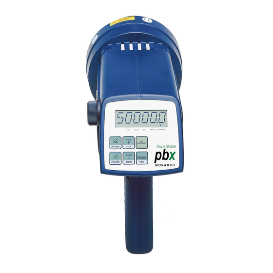
9.0 SPECIFICATIONS 1.0 OVERVIEW Internal Mode: The Phaser-Strobe pbx is an extremely sophisticated instrument with Flash Range 30 - 50,000 FPM (Flashes Per Minute) many features, yet remains simple to operate. Select only the features you 0.004% of setting or ± last digit Flash Rate Accuracy need. - Page 6 On Target Indicator for Tachometer Mode and Remote External Power Supply/Charger Sensor in External Mode The external power supply/charger (PSC-pbxU) can also be used to - - - - - Indicates input frequency exceeds the limit of the run the stroboscope continuously from the AC mains (115/230 Vac). stroboscope To power the strobe with the external power supply/charger (PSC- Battery indication, see section 8.1...
-
Page 7: Preparation For Use
The ALT FUNCTION button toggles ALT. in the display. When ALT. is by no flash and the display shows “LO BAT”. At this time the batteries must be recharged (section 8.2 Charging the Batteries) or displayed, the buttons will perform their secondary function listed in powered by the power supply/charger (section 8.3 External Power the lower section of each button. - Page 8 Common 8.0 BATTERY POWER SUPPLY Signal Input (GND) SPECIFICS +6V Out to +6V Out to Sensor Sensor The Phaser-Strobe pbx is fitted with rechargeable NiMH (Nickel Metal Common Hydride) batteries. These batteries contain fewer toxic metals than NiCd Signal Input (GND) (Nickel Cadmium) and are currently classified “environmentally friendly”.
-
Page 9: Menu
With no external input, the output jack ( pointing away from socket) Red Dots provides a TTL compatible pulse from the strobe’s internal oscillator. If an external input is applied, the output pulse is in sync with the input pulse. This output pulse may be used to trigger a second stroboscope synchronously to illuminate larger areas. -
Page 10: Operation
Below is a list of the menu items: The stroboscope is designed to discharge the internal high voltages D E C P T - Decimal Point (none, 1 or 2) within 30 seconds. However, caution should be exercised when replacing D E C P T D E C P T D E C P T... - Page 11 6.0 LIMITATIONS OF REMOTE OPTICAL To change the flash rate: With the power on, turn the knob counter clockwise to increase the flash SENSORS rate and clockwise to decrease it. The knob is velocity sensitive. Turn the Remote Optical Sensors have a limitation when used with the Phaser- knob slowly to have each “click”...
- Page 12 For example: A 3 bladed fan is spinning at 3600 RPM. The strobe is flashing at 3600 FPM. Press the ALT FUNCTION button to display ALT. Then turn the knob counter clockwise 2 clicks. The strobe will Stopped Image 1/4 times 1/2 times 1 time 2 times...
-
Page 13: Internal Mode - Tach Frequency Generator
5.0 USING THE STROBOSCOPE TO MEASURE Internal “Phase” Delay / Jog Once the flash rate has been adjusted to give a stopped motion image, the PHASE DELAY button may be used with the knob to increase or The primary use for a stroboscope is to stop motion for diagnostic inspection decrease the phase of the reference mark location. -
Page 14: External Input Mode
External Input Mode External Delay Modes (Phase Shifting) The strobe is in the External Input Mode whenever there is a plug in There are three External Delay Modes: Phase Delay, Time Delay, and the input jack. When the strobe is in the External Input Mode, EXT Auto (Virtual RPM).
Need help?
Do you have a question about the Phaser Strobe PBX and is the answer not in the manual?
Questions and answers