Table of Contents
Advertisement
Quick Links
Advertisement
Table of Contents

Subscribe to Our Youtube Channel
Related Manuals for MONARCH INSTRUMENT ACT-3X


Summary of Contents for MONARCH INSTRUMENT ACT-3X
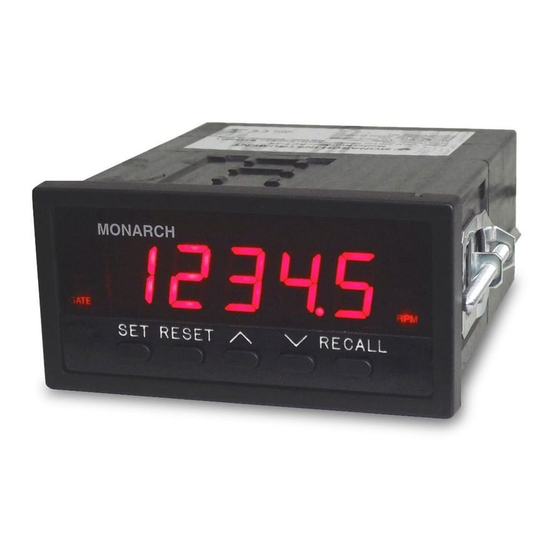
- Page 1 ACT-3X Tachometer / Totalizer / Ratemeter User Manual and Reference Guide MONARCH INSTRUMENT 15 Columbia Drive Amherst, NH 03031 USA Phone: (603) 883-3390 Fax: (603) 886-3300 E-mail: support@monarchinstrument.com Website: www.monarchinstrument.com...
- Page 2 This product needs to be RECYCLED in accordance with local regulations, contact your local authorities for more information. This product may be returnable to your distributor for recycling - contact the distributor for details. Monarch Instrument’s Limited Warranty applies. See www.monarchinstrument.com for details. Warranty Registration and Extended Warranty coverage available online at www.monarchinstrument.com.
-
Page 3: Table Of Contents
GENERAL OVERVIEW ................1 INSTALLATION ..................1 Noisy Environments ......................1 Adjustments ........................2 Connections ........................2 2.3.1 Power Connections....................2 2.3.2 Sensor Connections .................... 2 2.3.3 Analog Output ...................... 3 2.3.4 Auxiliary Input (AUX- Channel 2) ................ 3 2.3.5 Pulse Output ......................3 2.3.6 Alarm Relay Outputs.................... - Page 4 PULSE OUTPUT ........................ 8 USING THE MENU ..................8 ............................. 9 5.1.1 ........................9 5.1.2 ........................9 5.1.3 ........................9 5.1.4 ........................9 5.1.5 ........................10 ........................... 10 5.2.1 ........................10 5.2.2 ........................10 ...
-
Page 5: General Overview
GENERAL OVERVIEW The ACT-3X digital panel meter is an extremely versatile instrument. The user has complete control of the unit configuration. Power may be either 115 - 230 Vac (50/60 Hz), or optionally, 12 Vdc or 24 Vdc. Input signals are accepted (on Channel 1) from optical, proximity, magnetic, infrared or laser sensors, or direct TTL or external AC sources. -
Page 6: Adjustments
All connections are via the rear panel of the instrument – power, sensors, alarms, analog output, and communication. The rear panel is shown below and may vary slightly depending on what options are in the unit. Figure 2 ACT-3X Rear panel with Analog Output and USB Option 2.3.1 Power Connections Power to the unit is connected to the terminals under the sections labeled POWER on the rear panel. -
Page 7: Analog Output
NOTE: Sensor shields may be attached to input common (COM) if a ground point is not available. Figure 3 Sensor Connections 2.3.3 Analog Output The Analog Output is an option. The Output option is marked on the back of the unit to the right of the connector – refer to Figure 2.3.3.1 Current Output... -
Page 8: Serial Communications
2.3.7 Serial Communications There are three serial communication options – Ethernet, USB and RS232. The Ethernet option will have a standard RJ45 connector, the USB option will have a type B female connector, and the RS232 option will have a male DB9 connector on the rear panel. -
Page 9: Up () And Down () Buttons
the RESET button changes the digit being edited (blinking digit). Also when entering a data value, holding down the RESET button and pressing the DOWN () button will move the decimal place. 3.2.3 UP () and DOWN () BUTTONS The UP and DOWN buttons can be used to view the current settings of the alarms. Press the UP button to view LIMIT 1 or the DOWN ... -
Page 10: Totalizing Mode
Alarm Limits The ACT-3X has two independent alarm set points, referred to as LIMIT 1 and LIMIT 2 (Set 1 and Set 2 on the menu). These limits are fully programmable by the user (unless the write protect option has been set). The limits may be set as high or low with an option of low limit lockout, latching or non-latching at any value. -
Page 11: Latching Vs. Non-Latching Limits
Analog (AO) and Current (IO) Output The ACT-3X has options for voltage (0 to 5Vdc) or current (4 to 20mA) outputs. The analog outputs are derived from a 15-bit digital to analog converter. This means that the output voltage (or current) changes in steps. -
Page 12: Throughput
Throughput Throughput is a measure of how fast the instrument processes data. The rate at which the instrument acquires data is a function of the ―Gate Time‖ and the input frequency. The instrument gets a start pulse then it continues to get pulses until the Gate Time elapses. - Page 13 Decimal Point- Set the number of Decimal Points displayed on the unit Set point 1 - Set up parameters for Alarm 1 Set point 2 - Set up parameters for Alarm 2 Digital Analog Converter 1- Set up parameters for the Analog Output (Option) ...
- Page 14 5.1.4.1 12 SEC - Sets the Low End to 12 Seconds, equivalent to 5 RPM. 5.1.4.2 1 SEC - Sets the Low End to 1 Second, equivalent to 60 RPM. 5.1.4.3 HALF - Sets the Low End to 1/2 Second, equivalent to 120 RPM. 5.1.5 ...
- Page 15 5.4.4 FAIL SAFE - Press the SET button and use the UP button to select whether the Alarm is FAIL Safe – select YES, or NO. Press the SET button to select the new setting or the RECALL button to exit without saving the settings.
-
Page 16: Serial Output
5.11 Used to view the Serial Number of the unit. Use the SET button to view the serial number and the RECALL button to return to the main menu. 5.12 Display or set the pass code to protect the menu. When setting or entering a pass code, the edit buttons function as follows: RESET - changes the digit being edited (blinking digit) UP ... -
Page 17: Control Commands
Stop sending display data Unit stops sending display data Send last calculated reading This value is changed as fast as the throughput of the ACT unlike the @D0 command that gives the last displayed value which only changes up to 2 times per second. In the Rate of Change (ROC) mode this command will give the last RPM measured. -
Page 18: Specifications
@BAUD Will display the BAUD rate in kbyte/sec @ENET Will show the Ethernet Address settings. IP Address, Sub net mask and Gateway Address @OUTPT POS or NEG Select the polarity of the pulse output. @DSPLR HALF, 1_SEC, 1.5_S This sets the maximum display update rate to ½, 1 or 1½ second. @SERNO View the serial number of the unit. -
Page 19: Options And Accessories / Sensors
For use with units ordered with standard Serial Communications, phone plug. Enables the user to program the ACT-3X using a PC with USB connection. The software also allows remote monitoring of the RPM using a graphic display or an Excel spreadsheet. -
Page 20: Appendix A - Scaling The Act For Engineering Displays
APPENDIX A - SCALING THE ACT FOR ENGINEERING DISPLAYS The SCALE Mode must be used to display RPM in applications where there is more than one pulse per revolution. Below describes how to use this mode and other applications that need to be scaled. When using the scaling function of the ACT Tachometer it is possible to multiply the input signal by any value from 0.0001 to 99,999 making it possible to display the actual output in virtually any format. -
Page 21: Appendix B - Useful Conversions
Suppose we have wheel of d inches in diameter. This wheel turns the tire on a motor vehicle. We get one pulse into the tachometer for each revolution of the drive wheel. We want the display in miles per hour. We ignore slip. NOTE: For more than one pulse per revolution, simply divide the scale factor you get for one pulse by the number of actual pulses per revolution. -
Page 22: Appendix C - Using The Single Event Capture Mode
APPENDIX C – USING THE SINGLE EVENT CAPTURE MODE This is to how to calculate a scale factor and to show sources of measurement error. In this example, the distance between sensors is 1 inch and we want the readings displayed in Miles Per Hour (MPH). The fastest measurement we intend to make is 130 MPH. -
Page 23: Appendix D - Setting Up The Ethernet Interface
APPENDIX D – SETTING UP THE ETHERNET INTERFACE Connect an Ethernet cable from the ACT-3X device to your network. Note: The device MUST be connected to the same network as the computer on which you are going to run this setup. -
Page 24: Appendix E - Menu Overview
APPENDIX E – MENU OVERVIEW For more detail, refer to Section 5.0. SET - ENTER DATA: Press the SET button and use the buttons to set the required value. Press RECALL to exit up one level without making a change or press SET to make the change. The edit buttons function as follows: RESET - changes the digit being edited (blinking digit)
Need help?
Do you have a question about the ACT-3X and is the answer not in the manual?
Questions and answers