Table of Contents
Advertisement
Quick Links
Advertisement
Table of Contents

Related Manuals for MONARCH INSTRUMENT Nova-Strobe PBL


Summary of Contents for MONARCH INSTRUMENT Nova-Strobe PBL
- Page 1 Instruction Manual Nova-Strobe DBL Nova-Strobe PBL Deluxe and Phaser LED Stroboscopes 15 Columbia Drive • Amherst, NH 03031 USA Phone: (603) 883-3390 • Fax: (603) 886-3300 E-mail: support@monarchinstrument.com Website: www.monarchinstrument.com...
- Page 2 Safeguards Precautions Read and follow all instructions in this manual carefully, and retain this manual for future reference. Do not use this instrument in any manner inconsistent with these operating instructions or under any conditions that exceed the environmental specifications stated. Certain strobe frequencies can trigger epileptic seizures in those prone to that type of attack.
- Page 3 This product may be returnable to your distributor for recycling - contact the distributor for details. Monarch Instrument’s Limited Warranty applies. See www.monarchinstrument.com for details. Warranty Registration and Extended Warranty coverage available online at www.monarchinstrument.com.
-
Page 4: Table Of Contents
TABLE OF CONTENTS: 1.0 OVERVIEW .................. 2 1.1 LED Strobe Control Panel ..........2 1.2 Modes of Operation ............3 1.2.1 Internal Mode............. 3 1.2.2 External Mode ............3 1.2.3 Charging Mode ............3 2.0 GETTING STARTED ..............4 2.1 Power ................... 4 2.2 Input / Output Connections .......... - Page 5 3.7 Phase Delay ............... 10 3.7.1 Internal Phase Delay ..........10 3.7.2 External Delay (PBL Model ONLY) ......11 4.0 MENU ..................12 4.1 Decimal Places ..............12 4.2 Backlight ................12 4.3 Input Pulse Edge ............... 12 4.4 Output Pulse Polarity ............13 4.5 Blanking ................
-
Page 6: Overview
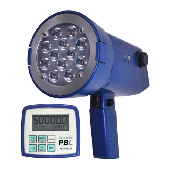
1.0 OVERVIEW The Nova-Strobe Deluxe DBL and Phaser PBL LED (Light Emitting Diode) are rugged portable battery powered LED Stroboscopes used for inspection and to stop motion to determine the speed of rotating objects. The units have a pistol grip with lockable trigger switch and wrist strap for comfortable hand held operation or they may be mounted on a tripod using the integral ¼... -
Page 7: Modes Of Operation
1.2 Modes of Operation The stroboscope has two basic modes of operation – INTERNAL and EXTERNAL. 1.2.1 Internal Mode The strobe is in the Internal Mode when nothing is plugged into the input jack or when manually set using the INPUT button. In the internal mode the strobe generates its own timing signals and the users can enter the flash rate using several different methods –... -
Page 8: Getting Started
2.0 GETTING STARTED The Stroboscope may be hand held or mounted on a tripod or other user supplied bracket using the ¼-20 UNC bushing at the base of the handle. 2.1 Power The LED Strobe is battery powered and has internal rechargeable batteries. - Page 9 Common (GND) Signal Input +6V Out to Sensor +6V Out to Sensor Signal Input Common (GND) Figure 2 Input Connector Detail (Stereo plug) Pulse Output Common (GND) from Strobe Pulse Output Common (GND) from Strobe Figure 3 Output Connector Detail (Mono plug) The input jack (...
-
Page 10: Led Strobe Operation
the next strobe causing all the strobes to flash together and be controlled by the first strobe in the chain. The polarity of the output pulse can be set in the MENU options. 3.0 LED STROBE OPERATION 3.1 Adjusting the Flash Rate - RPM There are several ways to adjust the flash rate of the Strobe: 3.1.1 Using the Knob The flash rate can be adjusted by turning the knob on the side of the... -
Page 11: Multiply Or Divide By 2
Each time the button is pressed the blinking digit moves one position to the right, the decade decreases by 10 until the digits stop blinking. Pressing the button again will cause the left most digit to start blinking. 888888 >... -
Page 12: Adjusting The Flash Duration (Brightness)
will increase the flash rate by N (300 in this example) for each click or turning it clockwise will decrease the flash rate by N. It is not possible to decrement the flash rate below 30 FPM. 3.2 Adjusting the Flash Duration (Brightness) The flash duration, the width of the LED flash, can be adjusted by the user to be a preset number of degrees of rotation (DEGS) or a fixed with in microseconds (uSEC). -
Page 13: Display Units
may be calculated from phase degrees set above. Use the knob to increase or decrease the flash duration in microseconds. Adjusting the microseconds will uSECS cause this to be the controlling parameter for pulse width. As the flash rate increases or decreases the strobe will keep the flash duration at the preset width in microseconds provided this does not exceed the strobe specifications. -
Page 14: Mode Selection
3.5 Mode Selection The INPUT button, shown right, toggles between the INTERNAL and EXTERNAL Modes as described in Section 1.2. When in the external mode the display will show EXT and the stroboscope will only flash with an external input. Plugging in an external source will cause the unit to automatically switch to the EXTERNAL mode. -
Page 15: External Delay (Pbl Model Only)
To adjust the phase or jog the image, press the DELAY button. PHASE will be displayed on the bottom line of the LCD display and the current flash rate will be displayed on the top line. Turning the knob adjusts the phase of the stopped image. -
Page 16: Menu
and will indicate VRPM (Virtual RPM) on the lower line. The knob adjusts the virtual speed in RPM, counterclockwise to increase and clockwise to decrease. 4.0 MENU The Menu allows settings of basic setup options – displayed decimal places, backlight on or off, positive or negative edge for input and output signal and blanking. -
Page 17: Output Pulse Polarity
and press the MENU button again. The top line of the display will show the (for positive edge triggered) or (for negative edge triggered) selected by rotating the knob counterclockwise (PoS) or clockwise (nEg). Press the MENU button to select, then any other key to exit. The display will show DONE and return to the normal readout. -
Page 18: Calculating Blur
human eye (the ability to remember and image) and its response to bright light to give an apparent stop motion image. Imagine a shaft rotating at 6000 RPM or one rotation every 1/100 of a second (10 msec). If the strobe flashes once every 10 msec for a brief moment, the user sees the flash at the same spot in the rotation of the shaft and the persistence of the eye remembers this until the next flash making the shaft appeared to be stopped. -
Page 19: Brightness In Pulse Duration
the target is. Optimal setting to stop motion is 1.8 to 3.6°. The number of degrees is a proportional amount and remains constant as the flash rate increases or decreases. The strobe automatically calculates how wide the pulse width should be at different flash rates to keep the blur constant – the faster the flash rate the narrower the pulse width. - Page 20 bolt, key way or imperfection to use as a reference point. If the object being viewed is perfectly symmetrical, then the user needs to mark the object with a piece of tape or paint in a single location to be used as a reference point. Look only at the reference point.
-
Page 21: Batteries
of the first SINGLE image you encounter, call this speed “A”. Continue decreasing the flash rate until you encounter a second SINGLE image. Note this speed as “B”. Continue decreasing the speed until you reach a third SINGLE image at speed “C”. For a two point calculation the actual speed is given by: RPM = AB/(A-B) For a three point calculation:... -
Page 22: Low Battery Indication
When not in use, the batteries should be charged at least every three months, otherwise the battery capacity will be reduced or the batteries may become unusable. Charge the batteries before use and allow 3-5 cycles of charging and discharging for batteries to reach full capacity. The enclosure contains control electronics to properly and safely charge the batteries. -
Page 23: External Power Supply/Charger (Pbl Only)
CAUTION: Use of rechargers other than the one supplied (PSC-2U for the DBL and PSC-PBXU for the PBL) will damage the stroboscope and void the warranty. When the recharger plug is inserted into the recharger jack, the strobe will go into the Charging Mode. Make sure the trigger switch is not depressed. The DBL strobe will not do anything else when charging (e.g. -
Page 24: Stroboscope Disposal
7.4 Stroboscope Disposal Prior to disposing of the battery-powered strobe, the user must remove the Nickel-Metal Hydride batteries. To do this, remove the LED assembly first. This will expose four (4) screws that must be removed so the reflector housing can be dismantled. There are four (4) additional screws in the case half opposite the input and output jacks that must be removed. - Page 25 Knob Adjustment Digital Rotary switch with 36 detents per revolution; velocity sensitive Memory Last setting before power down is remembered and restored on next power up. 5 user settable flash rates. Input Power Battery powered: Internal Rechargeable Batteries 6 Vdc, External AC Power Supply PBL only (100 Vac to 240 Vac, 50/60 Hz) Light Output Average: 3000 Lumens @ 6000 FPM 12”...
-
Page 26: Sensors, Accesories, And Parts
9.0 SENSORS, ACCESORIES, AND PARTS Sensors and Accessories: Remote Optical Laser Sensor with 8 foot [2.5 m] cable for triggering ROLS-P strobe. 6180-029 Remote Optical Sensor with 8 foot [2.5 m] cable for triggering strobe. ROS-P 6180-057 Remote Optical Sensor with 25 foot [7.6 m] cable for triggering strobe. ROS-P-25 6180-057-25 Infrared Sensor with 8 foot [2.5 m] cable for use without reflective target... -
Page 27: Replacement Parts
Protective rubber boot for all Nova-Strobe X Series strobes that fits over Protective reflector housing to protect strobe. Rubber Cover 6280-048 Reflective tape - 5 foot [1.5m] roll, 0.5 inch [12.7mm] wide 6180-070 Replacement Parts: Universal recharger, 115/230 Vac with USA, U.K., AUS, Euro PSC-2U Adapter Plugs for battery operated Nova-Strobes (included with DBL). - Page 28 Check out some of our other product lines… Handheld Panel Portable Machine Vision Tachometers Tachometers Stroboscopes Stroboscopes Speed Sensors Temperature/ Vibration Meters Humidity Sensors Paperless Recorders Track-It™ Data Loggers Printed in the U.S.A. © Copyright 2018 Monarch Instrument, all rights reserved. 1071- 4231-112 - 0418 JH...
Need help?
Do you have a question about the Nova-Strobe PBL and is the answer not in the manual?
Questions and answers