Advertisement
Available languages
Available languages
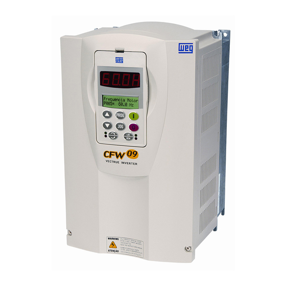
Frequency Inverter
CFW-09
Installation Guide
Language: English
VDC3 – CFW-09 24 VDC External Control Supply Accessory
ATTENTION!
Application with VDC3 card and inverters with rated current > 600 A, it is required to use CFW-09 inverters
with special firmware version "TR" (as specified in the nomenclature of the inverter).
1 CONTENTS OF THE PACKAGE
2 INVERTER SETTINGS
1. P214 = 0: It disables the Phase Loss.
2. P268 = 4: It sets the DI6 input for No External Error (it generates E06 if the supply voltage becomes lower than 18 Vdc).
3 VDC3 SETTINGS
S1 DIP switch:
With the frame sizes 1 to 7, 8, 9 and 10 it must remain always open (Off);
With the frame sizes 8E and 10E it must remain always closed (On);
- Open (Off) = It indicates "sub" or E02 in an undervoltage or input phase loss event at the CFW-09 input;
- Closed (On) = It indicates E70 in an undervoltage or input phase loss event at the CFW-09 input.
4 INSTALLATION
1. At the frame sizes 1 and 2 the VDC3 must be mounted near the inverter. At the frame sizes 3 and bigger, it can be mounted inside the
inverter, on the 4 holes near the CC9 board.
2. Connect the two-wire cable between the CC9 XC12 and the VDC3 XC1, (unplug the CC9 XC12 connector).
3. Connect one ribbon cable between the CC9 XC2 and the VDC3 XC2A.
4. Connect the other ribbon cable between the CC9 XC2B and the DPS or the power board.
5 ELECTRICAL INSTALLATION
Description
VDC3 electronic board
26 wire 300 mm ribbon cable
2 wire black/red twisted cable
9.5 mm plastic standoff
Installation guide
External supply
+
18 ... 30 Vdc 20 W
-
Quantity
1
2
1
4
1
DPS or power
board
CC9
Connector XC1
1
DI1
2
DI2
3
DI3
4
DI4
5
DI5
6
DI6
. .
7
COM
8
COM
9
24 Vdc
10
DGND*
CFW-09 VDC3 | 1
Advertisement
Table of Contents

Related Manuals for WEG CFW-09


Summary of Contents for WEG CFW-09
- Page 1 With the frame sizes 8E and 10E it must remain always closed (On); - Open (Off) = It indicates “sub” or E02 in an undervoltage or input phase loss event at the CFW-09 input; - Closed (On) = It indicates E70 in an undervoltage or input phase loss event at the CFW-09 input.
- Page 2 Com as mecânicas 8E e 10E deve permanecer sempre fechada (On); - Aberta (Off) = Indica “Sub” ou E02 em caso de subtensão ou falta de alimentação na entrada do CFW-09; - Fechada (On) = Indica E70 em caso de subtensão ou falta de alimentação na entrada do CFW-09.
Need help?
Do you have a question about the CFW-09 and is the answer not in the manual?
Questions and answers