Advertisement
SOYAL
ACCESS CONTROL SYSTEM
Contents
1
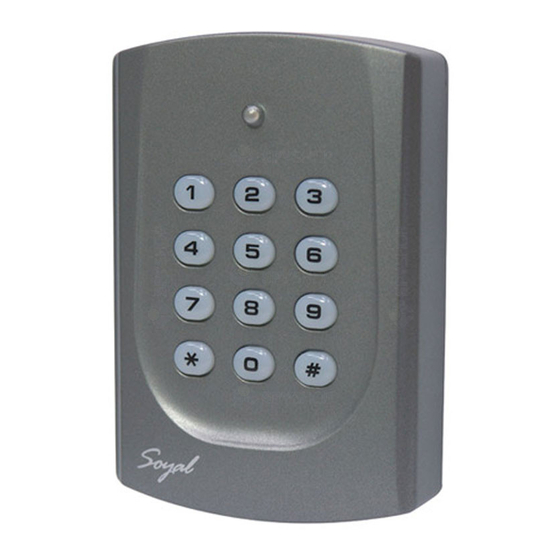
Product
2
User Guide
Specification
Users
500
Digits
3-6
Power Supply 9-16VDC / 100mA Indicator
Front Panel Indicators
The unit should make a beep sound when any key on the keypad is depressed.
If no key is made within 30 seconds, it will automatically exit the programming mode.
In the programming mode: LED lightgreen and flash rapidly, it means that the unit waits for entering.
In the programming mode:
One beep sound mean acknowledge, two beep sounds mean not acknowledge.
Installstion
4
Terminator
CN1
Wire Appllcation Wire Description
CN1
Relay_A
N.C.
1
N.O.
2
COM
3
ERG
4
DLY
5
CN2
GND
6
Exit Switch
12V
7
Power
Wiring Diagram
GND
POWER
12V
12VDC
Electric Bolt
N.O.
EXIT
Request To Exit
Delete user(s) code and Enable to system
Delete (Remove) a User Code from the system
Press
123456
(or Master Code) → 14
[e.g.] Delete User address 10: Access programming mode → 14
Delete (Remove) all Users Codes from the system
Press
123456
(or Master Code) → 29
Delete (Remove) a User Code from the controller
If you would like to delete all user codes. Remove the AR-721KP from the mounting plate. Press and hold the reset switch 10 seconds (RESTER, on
the KEYPAD circuit board). LED light green during 5 seconds and six beep sounds mean that all user are deleted.
®
3
Tools
4
f x2
Power consumption
< 2W
Operating Temperature -20℃ to +60℃
1 Bi-Color LED&1Beeper Dimensions(mm) 111(L) x 77(W) x 26(H)
LED is red and flash rapidly, it means the reader is busy.
Pull the cables from the square hole of the mounting plate.
Use a screwdriver to screw the base onto the wall.
Connect the terminal cables to the body and attach the body to the mounting plate.
Assemble the covers with the Allen key and screws (accessories supplied).
Turn on the power and LED will light and beep will sound.
N.C.
1
N.C.
N.O.
2
N.O.
COM
3
COM
EGR
4
Negative Trigger Input for Relay_A
DLY
5
Negative Trigger Input for Relay_B
VIN-
6
DC Power GND
VIN+
7
DC Power 12V
Diode
Electric Strike
CN1
1
2
N.O.
Keypad
COM
3
EGR
4
DLY
5
6
7
CN2
1 2 3 4 5 6
UUU
→Done ( A green light and beep means that the user code was deleted. )
29
→Done (The LED flash red during 1 second to mean that the system is deleting all user codes.
AR-721KP
Specification
Up to 500 pin-codes programmable from keypad.
Two access groups, each have request to exit inputs to control.
Default value: first group= 000~249 (Relat_A); second group= 250~499 (Relay_B).
2 relay outputs contact support latching or momentary outputs.
Built-in watchdog to prevent the system from halting.
Built-in tamper switch, include external security system interface.
Bell output, Press
+
together for bell using. (Optional)
Keypad will be locked for 30 seconds while continuous error operation.
Memory
Color
CN2
Wire Appllcation Wire Description
Relay_B
T a m p e r
Switch
SGND
12V
POWER
GND
12VDC
N.O.
EXIT
Request To Exit
GND
POWER
12V
12VDC
010
→Done
Then a green light and beep means that all user codes were deleted. )
EEPROM
Gray/Silver
COM
1
COM
N.O.
2
N.O.
N.C.
3
N.C.
SW
4
N/O or N/C select via jumper
SW
5
COM
SGND
6
Signal Ground
Installation Notice
Don't equip controller and lock with the same power supply.
The power for controller may be unstable when the lock is
activating, that may make the controller malfunction.
The standard installation: Door relay and lock use the same
power supply, and controller use independent power supply.
V110810
Weight(g)
100±10
Housing Material ABS
Advertisement
Table of Contents

Related Manuals for Soyal AR-721KP


Summary of Contents for Soyal AR-721KP
- Page 1 Delete (Remove) a User Code from the controller If you would like to delete all user codes. Remove the AR-721KP from the mounting plate. Press and hold the reset switch 10 seconds (RESTER, on the KEYPAD circuit board). LED light green during 5 seconds and six beep sounds mean that all user are deleted.
- Page 2 Factory Reset by its commands If the master code is forgotten it can be restored to the factory default. Remove the AR-721KP from the mounting plate. Press and hold the reset switch 5 seconds. LED light green during 2.5 seconds and five beep sounds mean that master code have restored to the factory default 123456.
Need help?
Do you have a question about the AR-721KP and is the answer not in the manual?
Questions and answers