Omron CJ1W-PRT21 Operation Manual
Profibus-dp slave unit
Hide thumbs
Also See for CJ1W-PRT21:
- Operation manual (127 pages) ,
- Operation manual (172 pages) ,
- Operation manual (317 pages)
Table of Contents
Advertisement
Quick Links
Download this manual
See also:
Operating Manual
Advertisement
Chapters
Table of Contents
Troubleshooting

Related Manuals for Omron CJ1W-PRT21


Summary of Contents for Omron CJ1W-PRT21
- Page 1 Cat. No. W408-E2-02-X CJ1W-PRT21 PROFIBUS-DP Slave Unit OPERATION MANUAL...
- Page 2 CJ1W-PRT21 PROFIBUS-DP Slave Unit Operation Manual Produced January 2005...
- Page 4 OMRON Product References All OMRON products are capitalized in this manual. The word “Unit” is also capitalized when it refers to an OMRON product, regardless of whether or not it appears in the proper name of the product.
-
Page 6: Table Of Contents
TABLE OF CONTENTS PRECAUTIONS ........Intended Audience ............General Precautions . - Page 7 GSD file for CJ1W-PRT21 ........
-
Page 8: About This Manual
About this Manual This manual describes the installation and operation of the CJ1W-PRT21 PROFIBUS-DP Slave Unit and includes the sections described below. Please read this manual carefully and be sure you understand the information provided before attempting to install or operate the PROFIBUS-DP Slave Unit. Be sure to read the precautions pro- vided in the following section. -
Page 10: Precautions
PRECAUTIONS This section provides general precautions for using the CJ-series Programmable Controllers (PCs) and related devices. The information contained in this section is important for the safe and reliable application of Programmable Controllers. You must read this section and understand the information contained before attempting to set up or operate a PC system. -
Page 11: Intended Audience
It is extremely important that a PC and all PC Units be used for the specified purpose and under the specified conditions, especially in applications that can directly or indirectly affect human life. You must consult with your OMRON representative before applying a PC System to the above-mentioned applica- tions. - Page 12 Safety Precautions !WARNING Do not touch any of the terminals or terminal blocks while the power is being supplied. Doing so may result in electric shock. !WARNING Do not attempt to disassemble, repair, or modify any Units. Any attempt to do so may result in malfunction, fire, or electric shock.
-
Page 13: Operating Environment Precautions
Operating Environment Precautions Operating Environment Precautions !Caution Do not operate the control system in the following locations: • Locations subject to direct sunlight. • Locations subject to temperatures or humidity outside the range specified in the specifications. • Locations subject to condensation as the result of severe changes in tem- perature. -
Page 14: Application Precautions
Application Precautions Application Precautions Observe the following precautions when using the PROFIBUS-DP Slave Units or the PLC. !WARNING Failure to abide by the following precautions could lead to serious or possibly fatal injury. Always heed these precautions. • Always ground the system to 100 Ω or less when installing the system to protect against electrical shock. - Page 15 Application Precautions !Caution • Be sure that all mounting screws, terminal screws, and cable connector screws are tightened to the torque specified in the relevant manuals. Incorrect tightening may result in malfunction. • Leave the label attached to the Unit when wiring. Removing the label may result in malfunction if foreign matter enters the Unit.
-
Page 16: Conformance To Ec Directives
Concepts EMC Directives OMRON devices that comply with EC Directives also conform to the related EMC standards so that they can be more easily built into other devices or the overall machine. The actual products have been checked for conformity to EMC standards (see the following note). - Page 17 Conformance to EC Directives Countermeasures taken to satisfy the standards vary depending on the devices on the load side, wiring, configuration of machines, etc. Following are examples of countermeasures for reducing the generated noise. Countermeasures (Refer to EN50081-2 for more details.) Countermeasures are not required if the frequency of load switching for the whole system with the PC included is less than 5 times per minute.
-
Page 18: Conformance To Ec Directives
Conformance to EC Directives When switching a load with a high inrush current such as an incandescent lamp, suppress the inrush current as shown below. Countermeasure 1 Countermeasure 2 Providing a dark current of Providing a limiting resistor approx. one-third of the rated value through an incandescent lamp xvii... - Page 19 Conformance to EC Directives xviii...
-
Page 20: Profibus-Dp
SECTION 1 PROFIBUS-DP This section provides a brief description of PROFIBUS-DP Introduction ........... Protocol architecture . -
Page 21: Introduction
Introduction Section 1-1 Introduction PROFIBUS is a vendor-independent, open fieldbus standard for a wide range of applications in manufacturing, process and building automation. Vendor independence and openness are guaranteed by the PROFIBUS standard EN 50170. With PROFIBUS, devices of different manufacturers can commu- nicate without special interface adjustments.The PROFIBUS family consists Standard EN50170 of three compatible versions:... - Page 22 Protocol architecture Section 1-2 DP-Profiles DP-Extensions User Interface Layer DP Basic Functions (7) Application Layer (6) Presentation Layer (5) Session Layer NOT DEFINED (4) Transport Layer (3) Network Layer (2) Data Link Layer Fieldbus Data Link (FDL) (1) Physical Layer RS-485 / Fibre Optics Layer 1, 2 and user PROFIBUS-DP uses layers 1 and 2, and the user interface.
-
Page 23: Device Types
They do not have bus access rights and they can only acknowledge received messages or send messages to the master when requested to do so. Slaves are also called pas- sive stations. The CJ1W-PRT21 is a PROFIBUS-DP slave device. -
Page 24: Profibus-Dp Characteristics
PROFIBUS-DP characteristics Section 1-4 PROFIBUS-DP characteristics 1-4-1 Bus Access Protocol Layer 2 The bus access protocol is implemented by layer 2. This protocol also includes data security and the handling of the transmission protocols and messages. Medium Access Control The Medium Access Control (MAC) specifies the procedures which determine when a station is permitted to transmit data. -
Page 25: Data Throughput
PROFIBUS-DP characteristics Section 1-4 Multi-peer communication In addition to logical peer-to-peer data transmission, PROFIBUS-DP provides multi-peer communication (broadcast and multicast). Broadcast communication: an active station sends an unacknowledged message to all other stations (masters and slaves). Multicast communication: an active station sends an unacknowledged message to a predetermined group of stations (masters and slaves). -
Page 26: Protection Mechanisms
PROFIBUS-DP characteristics Section 1-4 1-4-4 Protection mechanisms Time monitoring PROFIBUS-DP provides effective protection functions against parameterisa- tion errors or failure of the transmission equipment. Time monitoring is pro- vided at the DP master and at the DP slaves. The monitoring interval is spec- ified during the configuration. -
Page 27: Device Data Base Files
Device Data Base files Section 1-5 Device Data Base files GSD-file To achieve straightforward configuration of a PROFIBUS-DP network, the characteristic features of a device are specified in a file. This file is called a GSD-file (Gerätestammdaten file). The language of the GSD file is expressed with the last letter from the extension, *.GS?: Default: =GSD... -
Page 28: Features And System Configuration
SECTION 2 Features and System Configuration This section describes the overall specification and the communication performance of the PROFIBUS-DP CJ1W-PRT21 Slave Unit Overall Specification.......... -
Page 29: Overall Specification
Overall Specification Section 2-1 Overall Specification Modal code CJ1W-PRT21 Host PLC System Maximum number of Units per PLC system Current consumption 400 mA (maximum) at 5V DC from PLC power supply Weight 90 g (typical) Storage temperature C to +70... -
Page 30: Dimensions
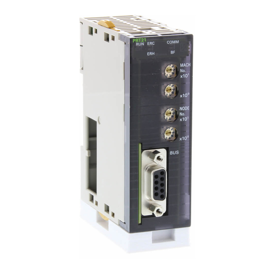
Dimensions Section 2-2 Dimensions The following figure shows the dimensions of the Unit. (All dimensions are in mm.) 31 mm 5 mm 65 mm PRT21 RUN ERC COMM Indicator LEDs MACH Rotary switches NODE 90 mm D-SUB 9 connector... -
Page 31: Performance
Consistency The CJ1W-PRT21 guarantees consistency over the full length of the PROFI- BUS data message, i.e. all I/O data in one PROFIBUS message is transferred to the host PLC in one I/O refresh, and vice versa. There are added modules... - Page 32 The minimum time interval between subsequent I/O data exchanges with the CJ1W-PRT21 (minimum slave interval) is 0.5 ms as defined in the Unit’s GSD file. PLC cycle time The host PLC’s cycle time mainly depends on the size of the PLC program...
-
Page 34: Installation
Installation This section describes the installation of the PROFIBUS-DP CJ1W-PRT21 Slave Unit Physical layout of the Unit ........ -
Page 35: Physical Layout Of The Unit
LED functions. 3-1-2 Rotary Switches The CJ1W-PRT21 has 4 rotary switches to: • set its Special I/O Unit number or Machine No. (00-95) • set the PROFIBUS-DP node address (00-99) Note Always turn off the power to the PLC before changing a rotary switch setting. - Page 36 Special I/O Unit connected to the PLC. If the same number is used for the CJ1W-PRT21 and another Special I/O Unit, an Unit/Rack Num- ber Duplication error (FALS 80E9) will occur in the PLC, and it will not be pos- sible to start up the PROFIBUS-DP Slave communication see ( Appendix B Device specific parameters and diagnostics ).
-
Page 37: Connecting Pc Components
Connecting PC Components Section 3-2 VP, DGND The signals VP and DGND are meant to power an externally mounted bus termi- nator. 390Ω B-line The powering of the 220 Ω termination resistor ensures a defined idle state potential on the data lines. To ensure 220Ω... - Page 38 Connecting PC Components Section 3-2 2. The yellow sliders at the top and bottom of each Unit lock the Units together. Move the sliders toward the back of the Units as shown below un- til they click into place. Note If the locking tabs are not secured properly, the CJ-series PLC may not func- tion properly.
- Page 39 Connecting PC Components Section 3-2 !Caution Attach the End Cover to the Unit on the far right side of the Rack. An I/O bus error will occur and the PC will not operate in either RUN or MONITOR mode if the End Cover is not connected. If this occurs, the following information will be set in memory.
-
Page 40: Setting Up A Network
Setting up a network Section 3-3 Setting up a network 3-3-1 Fieldbus cabling Bus structure All PROFIBUS-DP devices are connected in a line structure. Each RS-485 bus segment may contain up to 32 stations (masters, slaves, repeaters). When more than 32 stations are required, repeaters must be used to link the individual bus segments. - Page 41 Setting up a network Section 3-3 Segment 1 Segment 2 Max. 31 Stations Max. 31 Stations Segment 3 Max. 31 Stations Segment 5 Segment 4 Max. 31 Stations Max. 31 Stations Master or slave station Segment 6 Max. 31 Stations Repeater Termination Max.
- Page 42 Section 3-3 Fieldbus connector The connector plug to be used on the CJ1W-PRT21 is a 9-pin male sub-D connector, preferably with a metal case, and a facility to connect the shield of the cable to the case. The cable should at least be connected to pin 3 (B-line) and pin 8 (A-line) of the connector.
- Page 43 Chk_Cfg message so that the slave can verify that the master’s expected I/O configuration for the slave is correct. The CJ1W-PRT21 Slave Unit will accept any in/ out words up to 100 input, 100 output words. The maximum of input + outputs must be 180 words or less.
- Page 44 Setting up a network Section 3-3 Fail safe support: Off: After the master sends a global control command ‘CLEAR’, the slave requires data telegramcontaining 0000 as data, in order to remain in data exchange mode. After the master sends a global control command ‘CLEAR’, the slave can accept data telegrams containing no data, while still remaining in data exchange mode Watchdog Base:...
- Page 45 PROFIBUS master. Example The example below shows a slave configuration screen. The CJ1W-PRT21 is configured as a slave with 2 words input for status information and (16+16+4=) 36 words input data and (16+16+8=) 40 words output data. The terms input and output are to be interpreted as seen from the PROFIBUS-DP master unit.
- Page 46 Setting up a network Section 3-3 Slave PLC status indication configured as Cyclic by first 2 input words If the Slave PLC status indication is configured as Cyclic by first 2 input words then the connections between master and slave are as follows: Master Slave IN word...
-
Page 48: User Interface
User Interface This section describes the Interface between the CJ1-series PLC CPU and the PROFIBUS-DP CJ1W-PRT21 Slave Unit. Input and Output Data......... . . -
Page 49: Input And Output Data
Section 4-1 Input and Output Data The CJ1W-PRT21 forms a link between two bus systems: the host PLC’s I/O bus on one side, and PROFIBUS-DP on the other. The Unit can be consid- ered as a slave to both systems: the I/O bus communication is controlled by the CPU Unit of the host PLC, the PROFIBUS-DP communication is control- led by a PROFIBUS-DP master. -
Page 50: I/O Data Mapping
I/O Area CIO 0080-0999 (Not used CIO 2960-3199 Data Link Area CIO 1000-1199 (Not allocated words CIO 1200-1499 CJ1W-PRT21 Internal I/O Areas CIO 3800-6143 CPU Bus unit area CIO 1500-1899 (Not allocated words Special I/O Unit Area Input buffer CIO 2000-2959 (Not allocated words Max. -
Page 51: I/O Data Format
Input + outputs must be 180 words or less. I/O Data Format The CJ1W-PRT21 allows the user to select between two methods to map the word-oriented PLC data to the essentially byte-oriented PROFIBUS-DP mes- sages. The default method is Motorola format (Big-Endian), which allows easy data exchange with other OMRON PROFIBUS-DP devices. -
Page 52: Data Mapping
Data Mapping Section 4-4 Data Mapping The mapping of PROFIBUS I/O data to the host PLC is controlled by the Set_Prm (set parameter) and Chk_Cfg (Check configuration) telegrams sent by the PROFIBUS Master. At startup of the PROFIBUS communication the following commands are sent. -
Page 53: Control And Status Area
CIO 2940-CIO 2949 4-5-2 Control bits The PROFIBUS-DP communication status of CJ1W-PRT21 can be controlled through the first CIO word (CIO n) allocated via the Machine No. setting (n = 2000 + 10*Mach.No.). The communication status set by these bits is retained until the Unit is restarted (Power-on or reset). -
Page 54: Status Flags
Section 4-5 4-5-3 Status Flags The CJ1W-PRT21 indicates its status in the second CIO word (CIO n+1) allo- cated via the Machine No. setting. The lower byte shows the PROFIBUS-DP related status information, the higher byte indicates configuration errors. At power-on, or after a reset of the unit, the initial value shall be 0000. - Page 55 Control and status area Section 4-5 CIO n+1.02 FREEZE 0: Not in FREEZE mode. 1: The slave has accepted a global control command FREEZE from its master. The slave input data from the PLC is not updated at the PROFIBUS-DP interface until the next FREEZE command to this slave, or until the slave receives an UNFREEZE command.
- Page 56 Control and status area Section 4-5 CIO n+1.06 Fail_safe enabled 0: After the master sends a global control command CLEAR, the slave requires data telegrams containing 0000 as data, in order to remain in data exchange mode. 1: After the master sends a global control command CLEAR, the slave can accept data telegrams containing no data, while still remaining in data exchange mode CIO n+1.08 Parameter/Configuration error...
- Page 57 Control and status area Section 4-5 CIO n+1.12 Incorrect start address for slave input area 0: No error 1: There is an error in the slave input area mapping. The start address of the area as specified in the Set_Prm telegram is invalid for this PLC CPU type.
-
Page 58: Configuration Information
Section 4-6 Configuration information The CJ1W-PRT21 provides 8 DM words to indicate configuration- and param- eterisation data received from the PROFIBUS-DP master unit. These words are not part of the cyclic refresh, but the unit writes this information to the Host PLC when the data in the unit changes. -
Page 59: Slave Parameter Data
Configuration information Section 4-6 4-6-2 Slave Parameter Data 15 14 13 12 11 10 Master address Group assignment Group 1 Group 2 Group 3 Group 4 Group 5 Group 6 Group 7 Group 8 Master Address low byte Hexadecimal value (00~7D) indicating the node address of the PROFIBUS-DP Master from which the Unit has received and accepted the Chk_Cfg and Set_Prm telegrams. - Page 60 Configuration information Section 4-6 15 14 13 12 11 10 D m+1 Watchdog factor 1 Watchdog factor 2 D m+1 Watchdog Factors The master's parameterisation telegram contains the value to which the slave's communication watchdog timer will be set. The actual watchdog control time is set to WDfact1 * WDfact2 * WD timebase.
-
Page 61: Slave Output Data
Configuration information Section 4-6 4-6-3 Slave Output Data 15 14 13 12 11 10 D m+2 Output area code Action on PROFIBUS fail Outputs Motorola/Intel mode D m+2 Output area code(data from Master to Slave PLC) low byte Indicates the area to which the unit will write PROFIBUS out- put data received from its master. - Page 62 Configuration information Section 4-6 15 14 13 12 11 10 D m+3 Output start address D m+3 Output start address (data from Master to Slave PLC) Indicates the start address in the area indicated in D m+2, to which the PROFIBUS output data, received from the master, will be written.
-
Page 63: Slave Input Data
Configuration information Section 4-6 4-6-4 Slave Input Data 15 14 13 12 11 10 D m+5 Input area code Action on PLC PROGRAM mode Action on PLC fatal error Inputs Motorola/Intel mode Include PLC status as input data D m+5 Input area code (data from Slave PLC to Master) low byte Indicates the area to which the unit will write PROFIBUS input... - Page 64 Configuration information Section 4-6 D m+5 Action on PLC PROGRAM mode bit 8+9 Indicates how the slave will behave on PROFIBUS in case the host PLC is in PROGRAM mode (as opposed to RUN or MON- ITOR mode) 00: Slave has not been configured by a master (n.a.). 01: Continue data exchange, and provide diagnostics to the master.
- Page 65 Configuration information Section 4-6 15 14 13 12 11 10 D m+6 Input start address D m+6 Input start address (data from Slave PLC to Master) Indicates the start address in the area indicated in D m+5, from which the PROFIBUS input data will be read. The value is provided by the PROFIBUS master's Set_Prm telegram, and indicated in D m+6 after both the Set_Prm and Chk_Cfg telegrams have been accepted.
-
Page 66: Plc Status Information
PLC status information Section 4-7 PLC status information The user may specify that the first two input words to be sent over PROFIBUS will contain status information about the slave PLC. This information is also contained in the PROFIBUS-DP diagnostics, but access to cyclic I/O data may be easier than to diagnostics. -
Page 67: Leds
LEDS Section 4-8 LEDS CJ1W-PRT21 uses 5 LEDs to indicate the status of the Unit. PRT21 RUN ERC COMM The RUN, ERC and ERH LEDs indicate the status of the unit in general. The functions of these LEDs are described in the table below. -
Page 68: Troubleshooting And Maintenance
SECTION 5 Troubleshooting and Maintenance This section describes the troubleshooting procedures and maintenance operations needed to keep the PROFIBUS-DP network operating properly. Error Indicators ..........Troubleshooting . -
Page 69: Error Indicators
The Unit is not connected properly. Turn the power off, make sure that the Unit is con- occurred. nected properly and turn the power on again. The Unit is defective Replace the CJ1W-PRT21 Table 10 Start-up problems Description Possible cause Possible remedy No LEDs are ON or The PLC’s power is off... - Page 70 The PROFIBUS master unit is defective Replace the master unit. The Slave Unit is defective. Replace the CJ1W-PRT21. COMM LED is OFF The PROFIBUS configuration is not cor- Check CIO n+1.08 (Parameter/Configuration Error flag) and BF LED is flash- rect.
- Page 71 CIO n at master side. WatchDog is off Enable Watchdog. Slave Unit is defective. Replace the CJ1W-PRT21. No I/O data is Slave is not connected properly. Check the slave's connection to PROFIBUS. Are the correct pins connected, is the shield also connected, is...
-
Page 72: Maintenance
Maintenance Section 5-3 Maintenance This section describes the routine cleaning and inspection recommended as regular maintenance. 5-3-1 Cleaning Clean the PROFIBUS-DP Slave Units regularly as described below in order to keep it in optimal operating condition. • Wipe the Unit with a dry, soft cloth for regular cleaning. •... -
Page 73: Addition/Replacement Of Units
Plugging/unplugging of any node in a PROFIBUS-DP network is liable to result in a temporary increase of the communication cycle time. Do not plug or unplug the CJ1W-PRT21 on the PLC backplane while the PLC is powered. Doing so may result in damage to the Unit and/or the PLC sys-... -
Page 74: Gsd File For Cj1W-Prt21
NL-2132 JD Hoofddorp The Netherlands Automation & Drives Development Centre Zilverenberg 2 NL-5234 GM 's-Hertogenbosch The Netherlands ;******************************************************************************* Device DataBase File for CJ1W-PRT21 PLC I/O Slave Filename: OC_0602.GSD Version : 2.2000 Date November 16, 2004 (C) Copyright OMRON Corporation 2004 All Rights Reserved ;*******************************************************************************... - Page 75 Appendix Protocol_Ident ; Profibus-DP supported. Station_Type ; Station = DP-Slave. Slave_Family = 10 ; Slave family = 10 (PLC). Revision = "V2.2" ; Device revision 2.2. Hardware_Release = "V1.1" ; Hardware revision 1.1. ; (0991860-9A). Software_Release = "V2.0" ; Software revision 2.0. Bitmap_Device = "OC0602_R"...
- Page 76 Appendix ; 0.5 msec. ; DP-slave information ********************************************************/ Freeze_Mode_supp ; Freeze mode supported. Sync_Mode_supp ; Sync mode supported. Fail_Safe ; Fail safe supported. Modular_Station ; Modular station. Max_Module = 32 ; Maximum # of modules: 32. Max_Input_Len = 200 ; Maximum # of input bytes. Max_Output_Len = 200 ;...
- Page 77 Appendix PrmText=5 Text(0)="OFF" Text(4)="ON (default)" EndPrmText PrmText=6 Text(0)="10 ms (default)" Text(4)="1 ms" EndPrmText PrmText=7 Text(0)="PROFIBUS diagnostics only" Text(1)="Cyclic by first 2 input words" EndPrmText ExtUserPrmData=1 "Action on slave PLC PROGRAM mode" BitArea(0-1) 1 1-2 Prm_Text_Ref=1 EndExtUserPrmData ExtUserPrmData=2 "Action on slave PLC I/O bus fail" BitArea(2-3) 2 1-2 Prm_Text_Ref=1 EndExtUserPrmData...
- Page 78 Appendix EndExtUserPrmData ExtUserPrmData=9 "Output data on PROFIBUS fail" Bit(0) 0 0-1 Prm_Text_Ref=4 EndExtUserPrmData ExtUserPrmData=10 "Fail-Safe support" BitArea(4-7) 4 0,4 Prm_Text_Ref=5 EndExtUserPrmData ExtUserPrmData=11 "Watchdog Base" BitArea(0-3) 0 0,4 Prm_Text_Ref=6 EndExtUserPrmData ExtUserPrmData=12 "Slave PLC status indication" Bit(7) 0 0,1 Prm_Text_Ref=7 EndExtUserPrmData ; User parameter message definition *******************************************/ Max_User_Prm_Data_Len = 11 Ext_User_Prm_Data_Ref(0) = 10 Ext_User_Prm_Data_Ref(0) = 11...
- Page 79 Appendix Unit_Diag_Bit(0008) = "PLC in Program mode" Unit_Diag_Bit(0012) = "Invalid start address input area" Unit_Diag_Bit(0013) = "Invalid end address input area" Unit_Diag_Bit(0014) = "Invalid start address outp. area" Unit_Diag_Bit(0015) = "Invalid end address output area" ;Error messages in CPU word A400 Unit_Diag_Area = 16-23 Value (2) ="CPU Bus Unit error"...
- Page 80 Appendix Module = "16 words In (to master)" 0xDF ; 16 words In. EndModule Module = "=== Non-consistent I/O (S7) ===" 0x00 ; No consistency Endmodule ; (for S7 Master) ; I/O definitions: Module = " 1 word In/Out (No Cons.)" 0x70 ;...
- Page 81 Appendix...
-
Page 82: Device Specific Parameters And Diagnostics
Appendix B Device specific parameters and diagnostics Parameters The parameterisation of the passive stations by the master is first done in the start-up phase of the PROFIBUS-DP system and is also possible in the data exchange mode. The first 10 bytes of parameter data are defined by the PROFIBUS standard the additional 9 bytes are device specific. - Page 83 PROFIBUS-DP specifies standard diagnostics and extended diagnostics. The standard diagnostics have a fixed format defined in the PROFIBUS standard. The extended diagnostics are meant for user diagnostics. CJ1W-PRT21 provides extended diagnostics to inform the PROFIBUS master unit about the status of the slave unit and its host PLC.
-
Page 84: Plc Status Information Words
Appendix C PLC Status information words Fatal Errors A fatal error has occurred if the indicators have the following conditions in RUN or MONITOR mode. Power Supply CPU Unit Indicators Unit Indicator POWER ERR/ALM PRPHL COMM Connect a Programming Console to display the error message. The cause of the error can be determined from the error message and related Auxiliary Area flags and words. - Page 85 Appendix Error Program- Error Flag and Probable cause Possible remedy ming code (in word data Console A400) display Cycle CYCLE 809F A40108: The cycle time has Change the program to reduce the cycle Time TIME ERR Cycle Time exceeded the maximum time or change the maximum cycle time Overrun Too Long...
- Page 86 Appendix Error Program- Error Flag and Probable cause Possible remedy ming code (in word data Console A400) display Too Many 80E1 A40111: The probable causes are Correct the problem and then turn the power supply OFF and back ON. I/O Points MANY I/O Too Many I/ listed below.
- Page 87 Appendix Error Program- Error Flag and Probable cause Possible remedy ming code (in word data Console A400) display Unit/Rack UNIT No. 80E9 A40113: The same number has been Check the Machine numbers, eliminate Number DPL ERR Duplication allocated to more than one the duplications, and turn the Rack’s Duplica- Error Flag...
- Page 88 Appendix Error Program- Error Flag and Probable cause Possible remedy ming code (in word data Console A400) display Program PRO- 80F0 A40109: A29513: Differentiation over- After writing any changes to the pro- error GRAM Program flow error gram, switch to PROGRAM mode and (cont.) Error Flag Too many differentiated...
- Page 89 Appendix Error Program- Error Flag and Probable cause Possible remedy ming code (in word data Console A400) display Memory MEMORY 80F1 A40115: An error has occurred in See below. error Memory memory. A bit in A403 will Error Flag turn ON to show the location of the error as listed below.
- Page 90 Appendix Error Program- Error Flag and Probable cause Possible remedy ming code (in word data Console A400) display PC Setup 009B A40210: There is a setting error in Change the indicated setting to a valid error SETUP PC Setup the PC Setup. The location setting.
- Page 91 Appendix Error Program- Error Flag and Probable cause Possible remedy ming code (in word data Console A400) display Special I/O SIOU 0500 to A40202: An installed Special I/O Unit Change the registered I/O table. does not match the Special Unit Setup SETUP 055F Special I/O...
-
Page 92: Index
Index DM Settings Application, Precautions xiii Asynchronous Auto_Clear EC Directives EN50170 Endian (little vs big) Basic I/O Units ERC (LED) Basic I/O errors ERH (LED) Baud rate Error BF (LED) FAL Error Broadcast FALS Error – Indicators BUS Connector Troubleshooting BUS Parameters Fail-safe Cable... - Page 93 Index Intel/Motorola format Precautions Application xiii IORF Instruction General Operating environment Safety PROFIBUS LEDS, Indicators Cable See BF, COMM, ERC, ERH, RUN Cycle time DP, FMS, PA Length, See cable Profiles Low Voltage Directive Standard MACH No. (Switch) Refresh, I/O Machine number Repeater Maintenance...
- Page 94 Index – Token – Troubleshooting Unfreeze Unit settings Unsync Watchdog – Disabled (status flag) Factor...
- Page 95 Index...
-
Page 96: Revision History
Revision History A manual revision code appears as a suffix to the catalog number on the front cover of the manual. Cat. No. W408-E2-02-X Revision code The following table outlines the changes made to the manual during each revision. Page numbers refer to the previous version.
Need help?
Do you have a question about the CJ1W-PRT21 and is the answer not in the manual?
Questions and answers