Advertisement
Quick Links
GIGABIT
PoE
SWITCH
Q
I
uick
nstallation
M A N A G E D
Rack-Mount
Introduction
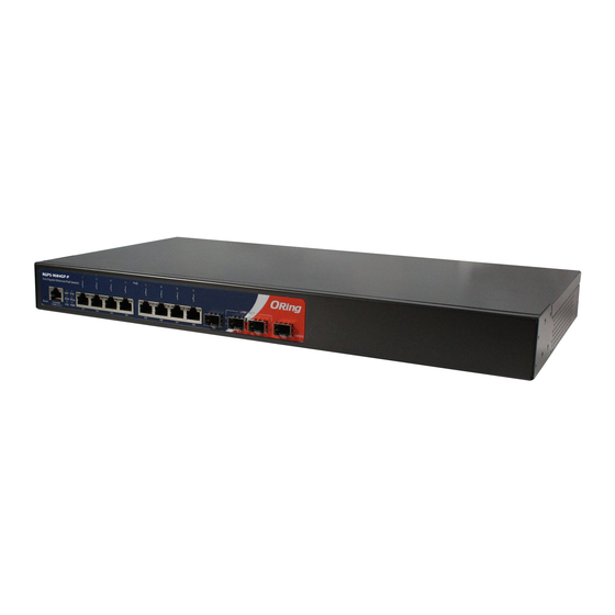
The
RGPS-9084GP-P
is managed PoE Ethernet switch with eight Gigabit
P.S.E. ports and four Gigabit SFP ports. The P.S.E ports can transmit
electrical power up to 30 watts per port (240watts in total between -40 ~
o
60 C and 120watts in total between 60 ~ 75 C) along with data to remote
devices over standard twisted-pair cables. The switch supports several
Ethernet redundancy technologies such as O-Ring (recovery time<30ms
over 250units of connection) and O-Chain topologies, as well as MSTP
protocol (RSTP/STP compatible) to protect mission-critical applications
from network interruptions or temporary malfunctions with fast recovery
technology. With a wide operating temperature from -40 C to 75 C, the
device can be managed centrally via ORing's proprietary Open-Vision
management utility as well as via Web-based interfaces, Telnet, and
console (CLI).
Package Contents
The device is shipped with the following items. If any of these items is
missing or damaged, please contact your customer service representative
for assistance.
Contents
Pictures
Number
RGPS-9084GP
X 1
-P
X 1
CD
X 1
QIG
Screw (M4 X6)
X 6
Rack-mounted
X 1
kit (L&R)
X 1
Power cord
X 1
Console Cable
Preparation
Before you begin installing the switch, make sure you have all of the package
contents available and a PC with Microsoft Internet Explorer 6.0 or later, for
using web-based system management tools.
Safety & Warnings
Elevated Operating Ambient: If installed in a closed or multi-unit rack
assembly, the operating ambient temperature of the rack environment may be
greater than room ambient. Therefore, consideration should be given to
installing the equipment in an environment compatible with the maximum
ambient temperature (Tma) specified by the manufacturer.
Q I G
RGPS-9084GP-P
RGPS-9084GP-P
G
uide
Reduced Air Flow:
amount of air flow required for safe operation of the equipment is not compromised.
Mechanical Loading:
o
hazardous condition is not achieved due to uneven mechanical loading.
Circuit Overloading:
the supply circuit and the effect that overloading of the circuits might have on overcurrent
protection and supply wiring. Appropriate consideration of equipment nameplate ratings
should be used when addressing this concern.
o
o
Dimension
185.25
RGPS-9084GP-P
PoE
Full Gigabit Ethernet PoE Switch
R.M.
Ring
R.M.
Reset
115200, 8, N, 1
Console
PWR Ring
PWR
G1
G3
G5
G7
Panel Layouts
RGPS-9084GP-P
PoE
Full Gigabit Ethernet PoE Switch
R.M.
R.M.
Ring
Reset
Console
PWR Ring
PWR
G1
G3
G5
G7
115200, 8, N, 1
1
2
3 4 5 6 7
8
1. Reset button
2. Console port
3. Power indicator
4. Ring status LED
5. RM status LED
6. LAN ports
1
2
AC 100-240V
50-60 HZ
1907-2-29-RGPS9084GPP-1.0
Installation of the equipment in a rack should be such that the
Mounting of the equipment in the rack should be such that a
Consideration should be given to the connection of the equipment to
380.00
49.0
2.65
6.50
15.90
19.00
58.00
26.70 24.00
443.70
3.90
LINK / ACT
1000X
1000X
G1
G3
G5
G7
G9
G10
G11
G12
R3.50
Front View
9
LINK / ACT
1000X
G1
G3
G5
G7
1000X
G9
G10
G11
G12
10 11
7. LNK/ACT indicator for Ethernet LAN ports
8. Speed indicator for Ethernet LAN ports
9. PoE indicator
10. SFP port
11. LNK/ACT LED for SFP ports
Rear View
1. Power switch
2. AC power input (100V~240V
/ 50~60Hz)
PRINTED ON RECYCLED PAPER
Managed Gigabit PoE Ethernet Switch
Installation
Rack-mounting
Step 1:
Install left and right front mounting brackets to the switch using three screws on each side.
Step 2:
With front brackets orientated in front of the rack, fasten the brackets to the rack using two
more screws.
Network Connection
The series have standard Ethernet ports. According to the link type, the switch uses CAT 3, 4,
5,5e UTP cables to connect to any other network devices (PCs, servers, switches, routers, or
hubs). Please refer to the following table for cable specifications.
Cable Types and Specifications:
Cable
Type
Max. Length
Connector
10BASE-T
Cat. 3, 4, 5 100-ohm
UTP 100 m (328 ft)
RJ-45
100BASE-TX
Cat. 5 100-ohm UTP
UTP 100 m (328 ft)
RJ-45
1000BASE-T
Cat. 5 / Cat. 5e 100-ohm UTP
UTP 100 m (328 ft)
RJ-45
For pin assignments for different types of cables, please refer to the following
tables.
10/100Base-T(X) P.S.E RJ-45 Port
1000Base-T P.S.E. RJ-45 port
Pin Number
Assignments
Pin Number
1
TD+ with PoE Power input +
#1
BI_DA+ with PoE Power input +
2
TD- with PoE Power input +
#2
BI_DA- with PoE Power input +
3
RD+ with PoE Power input -
#3
BI_DB+ with PoE Power input -
4
Not used
#4
5
Not used
#5
6
RD- with PoE Power input -
#6
BI_DB- with PoE Power input -
7
Not used
#7
8
Not used
#8
10/100Base-T(X) MDI/MDI-X Pin Assignments:
1000Base-T MDI/MDI-X Pin Assignments
Pin Number
MDI port
MDI-X port
Pin Number
MDI port
1
TD+(transmit)
RD+(receive)
1
BI_DA+
2
TD-(transmit)
RD-(receive)
2
BI_DA-
3
RD+(receive)
TD+(transmit)
3
BI_DB+
4
Not used
Not used
4
BI_DC+
5
Not used
Not used
5
BI_DC-
6
RD-(receive)
TD-(transmit)
6
BI_DB-
7
Not used
Not used
7
BI_DD+
8
Not used
Not used
8
BI_DD-
"+"
"-"
Note:
and
signs represent the polarity of the wires that make up each wire pair.
Quick Installation Guide
Version 1.0
Assignment
BI_DC+
BI_DC-
BI_DD+
BI_DD-
MDI-X port
BI_DB+
BI_DB-
BI_DA+
BI_DD+
BI_DD-
BI_DA-
BI_DC+
BI_DC-
Advertisement

Related Manuals for ORiNG RGPS-9084GP-P


Summary of Contents for ORiNG RGPS-9084GP-P
- Page 1 With a wide operating temperature from -40 C to 75 C, the device can be managed centrally via ORing’s proprietary Open-Vision Dimension management utility as well as via Web-based interfaces, Telnet, and console (CLI).
- Page 2 For more information Overload current protection 100~240VAC with power socket on configurations, please refer to the user manual. For information on operating the switch using ORing’s Open-Vision management utility, please Power consumption(Typ.) 17 Watts (PoE output not included) go to ORing website.
Need help?
Do you have a question about the RGPS-9084GP-P and is the answer not in the manual?
Questions and answers