Table of Contents
Advertisement
Quick Links
SWITCH
M A N A G E D
Q
I
Rack-Mount
uick
nstallation
Introduction
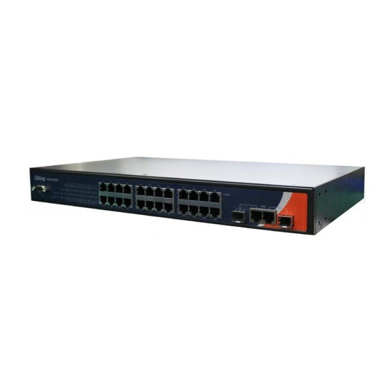
The
RES-9242GC
is a rackmount managed Ethernet switch designed for
industrial applications, such as rolling stock, vehicle, and railway
applications. Featuring twenty-four 10/100Base-T(X) ports and two Gigabit
combo ports, the device is able to meet the needs for high port density and
high-speed, long-distance transmission. With complete support for Ethernet
redundancy protocols such as O-Ring (recovery time < 30ms over 250 units of
connection) and MSTP (RSTP/STP compatible), the series can protect your
mission-critical applications from network interruptions or temporary
malfunctions with its fast recovery technology. Featuring a wide operating
o
o
temperature from -40 C to 75 C, the device can be managed centrally and
conveniently via Open-Vision, web browsers, Telnet and console (CLI)
configuration, making it one of the most reliable choice for highly-managed
and Fiber Ethernet power substation and rolling stock application.
Package Contents
The device is shipped with the following items. If any of these items is missing
or damaged, please contact your customer service representative for
assistance.
Contents
Pictures
Number
RES-9242GC
X 1
X 1
Console Cable
X 1
CD
X 1
QIG
Rack-mounted
X 1
kit (L&R)
X 2
Power Cable
Preparation
Before you begin installing the switch, make sure you have all of the package
contents available and a PC with Microsoft Internet Explorer 6.0 or later, for
using web-based system management tools.
Safety & Warnings
Elevated Operating Ambient:
If installed in a closed or multi-unit rack
assembly, the operating ambient temperature of the rack environment may be
greater than room ambient. Therefore, consideration should be given to
installing the equipment in an environment compatible with the maximum
ambient temperature (Tma) specified by the manufacturer.
Reduced Air Flow:
Installation of the equipment in a rack should be such
that the amount of air flow required for safe operation of the equipment is
not compromised.
Q I G
RES-9242GC
RES-9242GC
G
uide
Mechanical Loading:
hazardous condition is not achieved due to uneven mechanical loading.
Circuit Overloading:
to the supply circuit and the effect that overloading of the circuits might have on
overcurrent protection and supply wiring. Appropriate consideration of equipment
nameplate ratings should be used when addressing this concern.
Dimension
RES-9242GC
LNK
ACT
Fault
LNK
ACT
115200bps, 8, N,1
Console
Reset
Panel Layouts
6
RES-9242GC
LNK
ACT
Fault
LNK
ACT
115200bps, 8, N,1
Console
Reset
1
2 3
45
1. Console port
2. Reset button
3. Power indicator
4. Ring status LED
5. R.M status LED
1
1. Ground screw
2. AC power input (100V~240V / 50~60Hz)
Installation
Rack-mounting
Step 1:
Install left and right front mounting brackets to the switch using 4 M3 screws on each side.
Step 2:
With front brackets orientated in front of the rack, fasten the brackets to the rack using
two more screws.
1907-2-29-RES9242GC-1.0
Mounting of the equipment in the rack should be such that a
Consideration should be given to the connection of the equipment
G1
1000M
G2
Front View
7
G1
1000M
G2
8
9
10
6. Fault LED
7. Link/ACT LED for Ethernet ports and Combo ports
8. Speed LED for Ethernet ports and Combo ports
9. LAN ports
10. Combo ports
Rear View
2
PRINTED ON RECYCLED PAPER
Rack Mount Managed Ethernet Switch
Network Connection
The device comes with standard Ethernet ports. According to the link type, the switch uses CAT 3,
4, 5,5e UTP cables to connect to any other network devices (PCs, servers, switches, routers, or
hubs). Please refer to the following table for cable specifications.
Cable Types and Specifications:
Cable
Type
Max. Length
Connector
10BASE-T
Cat. 3, 4, 5 100-ohm
UTP 100 m (328 ft)
RJ-45
100BASE-TX
Cat. 5 100-ohm UTP
UTP 100 m (328 ft)
RJ-45
1000BASE-T
Cat. 5/Cat. 5e 100-ohm UTP
UTP 100 m (328ft)
RJ-45
For pin assignment, please refer to the following tables.
10/100Base-T(X) RJ-45 Port Pin Assignments
Pin No.
Assignment
1
TD+
2
TD-
3
RD+
6
RD-
10/100Base-T(X) MDI/MDI-X Pin Assignments
1000Base-T MDI/MDI-X Pin Assignments
Pin No.
MDI port
MDI-X port
Pin No.
MDI port
MDI-X port
1
TD+(transmit)
RD+(receive)
1
BI_DA+
2
TD-(transmit)
RD-(receive)
2
BI_DA-
3
RD+(receive)
TD+(transmit)
3
BI_DB+
4
Not used
Not used
4
BI_DC+
5
Not used
Not used
5
BI_DC-
6
RD-(receive)
TD-(transmit)
6
BI_DB-
7
BI_DD+
7
Not used
Not used
8
Not used
Not used
8
BI_DD-
Wiring
AC Power Connection
The device can be powered by AC electricity. Simply insert the AC power cable to the power
connector at the back of the switch and turn on the power switch. The input voltage is 100V~240V /
50~60Hz.
Grounding
The device provides grounding and wire routing to help limit the effects of noise due to
electromagnetic interference (EMI). Run the ground connection from the ground screws to the
grounding surface prior to connecting devices.
RS-232 Console Port Wiring
The device can be managed via the console port using a RS-232 cable which can be found in the
package. Connect each end of the RS-232 cable to the switch and a PC respectively.
Quick Installation Guide
Version 1.0
BI_DB+
BI_DB-
BI_DA+
BI_DD+
BI_DD-
BI_DA-
BI_DC+
BI_DC-
Advertisement
Table of Contents

Related Manuals for ORiNG RES-9242GC


Summary of Contents for ORiNG RES-9242GC
- Page 1 Version 1.0 SWITCH RES-9242GC Rack Mount Managed Ethernet Switch M A N A G E D Rack-Mount uick nstallation uide Introduction Mechanical Loading: Mounting of the equipment in the rack should be such that a RES-9242GC is a rackmount managed Ethernet switch designed for hazardous condition is not achieved due to uneven mechanical loading.
- Page 2 IEEE 802.1D Bridge, auto MAC address learning/aging and MAC address (static) Pin #2 RD Pin #2 TD Pin #2 Multiple Registration Protocol (MRP) information on operating the switch using ORing’s Open-Vision management utility, please go to ORing MSTP (RSTP/STP compatible) Pin #3 TD Pin #3 RD Pin #3 Redundant Ring (O-Ring) with recovery time less than 10ms over 250 units website.
Need help?
Do you have a question about the RES-9242GC and is the answer not in the manual?
Questions and answers