
Related Manuals for ORiNG RES-P3242GCL SERIES


Summary of Contents for ORiNG RES-P3242GCL SERIES
- Page 1 Industrial IEC 61850-3 Management Ethernet Switch RES-P3242GCL SERIES User’s Manual Version 2.0 JUN, 2012 ORing Industrial Networking Corp. Website: www.oring-networking.com E-mail: support@oring-networking.com...
-
Page 2: Table Of Contents
RES-P3242GCL SERIES User’s Manual Table of Content Getting to Know Your Switch ......................4 About the RES-P3242GCL SERIES Industrial Switch ..........4 Software Features ......................4 Hardware Features ......................4 Hardware Overview ..........................0 ... - Page 3 RES-P3242GCL SERIES User’s Manual 4.1.5 Multicast ......................... 28 4.1.5.1 IGMP Snooping ..................... 28 4.1.5.2 MVR ........................29 4.1.5.3 Multicast Filter ...................... 29 4.1.6 Port Setting ........................31 4.1.6.1 Port Control ......................
- Page 4 RES-P3242GCL SERIES User’s Manual 4.1.14 Save Configuration ....................66 4.1.15 Factory Default ......................66 4.1.16 System Reboot ......................67 Command Line Interface Management ..................68 About CLI Management ....................68 ...
-
Page 5: Getting To Know Your Switch
Switch RES-P3242GCL SERIES are powerful managed industrial switches for power station applications which have many features. RES-P3242GCL SERIES pass the IEC 61850-3 and IEEE 1613 certification. They can be managed by WEB, TELNET, Console or other third-party SNMP software as well. Besides, these switches can be managed by a useful utility that we called Open-Vision. - Page 6 RES-P3242GCL SERIES User’s Manual 2 x 10/100/1000Base-T(X) and 1000Base-X SFP ports on combo port 1 x Console Port Dimensions(W x D x H) : 443.7 mm(W)x 262.7 mm( D )x 44 mm(H) 19 inches rack mountable...
-
Page 7: Hardware Overview
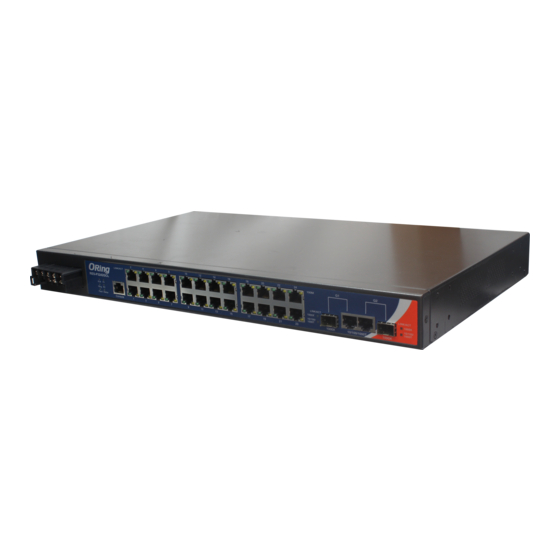
Overview 2.1 Front Panel The following table describes the labels that stick on the RES-P3242GCL SERIES. Port Description 10/100 RJ-45 fast 24 x 10/100Base-T(X) RJ-45 fast Ethernet ports support Ethernet ports auto-negotiation. Default Setting : Speed: auto Duplex: auto... -
Page 8: Power Panel
12. LED for Combo SFP ports Link / ACT status. 13. LED for Combo Copper ports Link / ACT status. 2.2 Power Panel RES-P3242GCL SERIES are power redundant switches, supports two power inputs. Note : RLY COM– Relay Com RLY NO – Relay Normal Open... -
Page 9: Rack Mount Kit Assembly
RES-P3242GCL SERIES User’s Manual 2.3 Rack mount kit assembly You can find the rack mount kit and the screws in the packing box. Please assembly the rack mount kit on the switch with screws as below picture. -
Page 10: Cables
3.1 Ethernet Cables RES-P3242GCL SERIES switches have standard Ethernet ports. According to the link type, these switches use CAT 3, 4, 5,5e UTP cables to connect to any other network device (PCs, servers, switches, routers, or hubs). Please refer to the following table for cable specifications. - Page 11 BI_DB- BI_DD+ BI_DD- The RES-P3242GCL SERIES switches support auto MDI/MDI-X operation. You can use a straight-through cable to connect PC to switch. The following table below shows the 10BASE-T/ 100BASE-TX MDI and MDI-X port pin outs. 10/100 Base-T MDI/MDI-X pins assignment...
-
Page 12: Sfp
RES-P3242GCL SERIES User’s Manual 3.2 SFP The RES-P3242GCL SERIES has fiber optical ports with SFP connectors. The fiber optical ports are in multi-mode (0 to 550M, 850 nm with 50/125 µm, 62.5/125 µm fiber) and single-mode with LC connector. Please remember that the TX port of Switch A should be connected to the RX port of Switch B. -
Page 13: Web Management
RES-P3242GCL SERIES User’s Manual EB Management 4.1 Configuration by Web Browser This section introduces the configuration by Web browser. 4.1.1 About Web-based Management Inside the CPU board of the switch, an embedded HTML web site resides in flash memory. It contains advanced management features and allows you to manage the switch from anywhere on the network through a standard browser such as Microsoft Internet Explorer. -
Page 14: Main Interface
RES-P3242GCL SERIES User’s Manual The login screen appears. Key in the username and password. The default username and password is “admin”. Click “Enter” or ”OK” button, then the main interface of the Web-based management appears. Login screen Main Interface Main interface... -
Page 15: System Information
RES-P3242GCL SERIES User’s Manual 4.1.2 System Information System Information interface System Information will display the configuration of Basic Setting / Switch Setting page. The following table describes the labels in this screen. Label Description Display the system name of switch. -
Page 16: Basic Setting
RES-P3242GCL SERIES User’s Manual 4.1.3 Basic setting 4.1.3.1 Switch Setting Switch setting interface The following table describes the labels in this screen. Label Description Assign the name of switch. The maximum length is 64 bytes System Name System Display the description of switch. -
Page 17: Ip Setting
RES-P3242GCL SERIES User’s Manual Confirm Re-type the new password. password Apply Click “Apply” to set the configurations. 4.1.3.3 IP Setting You can configure the IP Settings and DHCP client function through IP configuration. IP Configuration interface The following table describes the labels in this screen. -
Page 18: Sntp (Time)
RES-P3242GCL SERIES User’s Manual 192.168.10.254 DNS1 Assign the primary DNS IP address DNS2 Assign the secondary DNS IP address Apply Click “Apply” to set the configurations. 4.1.3.4 SNTP (Time) The SNTP (Simple Network Time Protocol) settings allow you to synchronize switch clocks in the Internet. - Page 19 RES-P3242GCL SERIES User’s Manual ADT - Atlantic Daylight -3 hours 9 am AST - Atlantic Standard -4 hours 8 am EDT - Eastern Daylight EST - Eastern Standard -5 hours 7 am CDT - Central Daylight CST - Central Standard...
- Page 20 RES-P3242GCL SERIES User’s Manual JST - Japan Standard, +9 hours 9 pm USSR Zone 8 EAST - East Australian Standard GST +10 hours 10 pm Guam Standard, USSR Zone 9 IDLE - International Date Line NZST - New Zealand +12 hours...
-
Page 21: Lldp
RES-P3242GCL SERIES User’s Manual 4.1.3.5 LLDP LLDP (Link Layer Discovery Protocol) function allows the switch to advertise its information to other nodes on the network and store the information it discovers. The following table describes the labels in this screen. - Page 22 RES-P3242GCL SERIES User’s Manual Backup & Restore interface The following table describes the labels in this screen. Label Description Fill in the TFTP server IP TFTP Server IP Address Fill the file name. Restore File Name Click “restore” to restore the configurations.
-
Page 23: Upgrade Firmware
RES-P3242GCL SERIES User’s Manual 4.1.3.7 Upgrade Firmware Upgrade Firmware allows you to update the switch firmware. Before updating, make sure you have your TFTP server ready and the firmware image is on the TFTP server. Update Firmware interface 4.1.3.8 Broadcast storm filter Set the broadcast storm rate to prevent network crash.. -
Page 24: Aging Time
RES-P3242GCL SERIES User’s Manual 4.1.3.9 Aging Time 1. Aging Time of MAC Table: Default 300secs. 2. Auto Flush MAC Table When Link Down: enable/disable the function 4.1.3.10 Jumbo Frame Enable/disable all ports Jumbo frame function. 4.1.4 Redundancy 4.1.4.1 O-Ring O-Ring is the most powerful Ring in the world. The recovery time of O-Ring is less than 10 It can reduce unexpected damage caused by network topology change. -
Page 25: Open-Ring
Note: We don’t suggest you to set one switch as a Ring Master and a Coupling Ring at the same time due to heavy load. 4.1.4.2 OPEN-Ring Open-Ring technology can be applied for other vendor’s proprietary ring. Thus, you can add switches of ORing into the network constructed by other ring technology and enable Open-Ring to co-operate with other vendor’s managed switch. -
Page 26: O-Rstp
RES-P3242GCL SERIES User’s Manual Click ”Connect to other vendor’s ring…..” to join the ring constructed by other vendor. Open-Ring interface Label Description Enable Enabling the Open-Ring function Vender Choosing the venders that you want to join to their ring Ring Port... -
Page 27: Rstp
RES-P3242GCL SERIES User’s Manual O-RSTP interface The application of O-RSTP is shown as below. O-RSTP connection 4.1.4.4 RSTP The Rapid Spanning Tree Protocol (RSTP) is an evolution of the Spanning Tree Protocol. It provides faster spanning tree convergence after a topology change. The system also supports STP and the system will auto detect the connected device that is running STP or RSTP protocol. - Page 28 RES-P3242GCL SERIES User’s Manual The following table describes the labels in this screen. Label Description You must enable or disable RSTP function before configuring RSTP mode the related parameters. A value used to identify the root bridge. The bridge with the...
- Page 29 RES-P3242GCL SERIES User’s Manual Label Description The cost of the path to the other bridge from this transmitting Path Cost (1-200000000) bridge at the specified port. Enter a number 1 through 200000000. Decide which port should be blocked by priority in LAN.
-
Page 30: Mstp
RES-P3242GCL SERIES User’s Manual The port includes the STP mathematic calculation. True is Admin Non STP not including STP mathematic calculation. False is including the STP mathematic calculation. Click “Apply” to set the configurations. Apply 4.1.4.5 MSTP Multiple Spanning Tree Protocol (MSTP) is a standard protocol base on IEEE 802.1s. The function is that several VLANs can be mapping to a reduced number of spanning tree instances because most networks do not need more than a few logical topologies. - Page 31 RES-P3242GCL SERIES User’s Manual MSTP Setting interface The following table describes the labels in this screen. Label Description MSTP Enable You must enable or disable MSTP function before configuring the related parameters. Force Version The Force Version parameter can be used to force a VLAN Bridge that supports RSTP to operate in an STP-compatible manner.
- Page 32 RES-P3242GCL SERIES User’s Manual Time, and Forward Delay Time at controlled switch sends out the BPDU packet to check RSTP current status. Enter a value between 1 through 10. 2 x (Forward Delay Time value –1) ≥ Max Age value ≥ 2 x (Hello Time value...
- Page 33 RES-P3242GCL SERIES User’s Manual be connected to exactly one other bridge (i.e. It is served by a point-to-point LAN segment), or it can be connected to two or more bridges (i.e. It is served by a shared medium LAN segment).
- Page 34 RES-P3242GCL SERIES User’s Manual MSTP Instance Port interface Label Description Instance Set the instance’s information except CIST Port Selecting the port that you want to configure. Priority (0-240) Decide which port should be blocked by priority in LAN. Enter a number 0 through 240.
-
Page 35: Multicast
RES-P3242GCL SERIES User’s Manual 4.1.5 Multicast 4.1.5.1 IGMP Snooping Internet Group Management Protocol (IGMP) is used by IP hosts to register their dynamic multicast group membership. IGMP has 3 versions, IGMP v1, v2 and v3. Please refer to RFC 1112, 2236 and 3376. IGMP Snooping improves the performance of networks that carry multicast traffic. -
Page 36: Mvr
RES-P3242GCL SERIES User’s Manual 4.1.5.2 MVR Function can provide a different VLAN users to receive MVR Mode VLAN Multicast Packet. Label Description Enable or Disable MVR Mode MVR Mode Setting MVR VLAN MVR VLAN Setting Port Type to inactive、Receiver、Source TYPE... - Page 37 RES-P3242GCL SERIES User’s Manual Multicast Filtering Interface The following table describes the labels in this screen. Label Description Assign a multicast group IP address in the range of 224.0.0.0 IP Address ~ 239.255.255.255 Tick the check box beside the port number to include them as Member Ports the member ports in the specific multicast group IP address.
-
Page 38: Port Setting
RES-P3242GCL SERIES User’s Manual 4.1.6 Port Setting 4.1.6.1 Port Control By this function, you can set the state, speed/duplex, flow control, and security of the port. Port Control interface The following table describes the labels in this screen. Label Description Port number for setting. -
Page 39: Port Alias
RES-P3242GCL SERIES User’s Manual 4.1.6.3 Port Alias The user can define the name of every port. That can let user to convenient management every port. 4.1.6.4 Rate Limit By this function, you can limit traffic of all ports, including broadcast, multicast and flooded unicast. -
Page 40: Port Trunk
RES-P3242GCL SERIES User’s Manual 4.1.6.5 Port Trunk Port Trunk – Setting You can select static trunk or 802.3ad LACP to combine several physical links with a logical link to increase the bandwidth. Port Trunk - Setting interface The following table describes the labels in this screen. - Page 41 RES-P3242GCL SERIES User’s Manual and can be aggregated if work ports fail. If it is local static trunk group, the number of ports must be the same as the group member ports. Select the ports to join the trunk group. Allow maximum four Add or Remove ports to be aggregated at the same time.
-
Page 42: Loop Guard
RES-P3242GCL SERIES User’s Manual Port Trunk – State Activity Label Description Port Port number LACP State Activity LACP Mode work status . 4.1.6.6 Loop Guard This feature prevents the loop attack, when the port receives loop packet. This port will auto... -
Page 43: Vlan
RES-P3242GCL SERIES User’s Manual Label Description Active Loop Guard Enable or Disable Port Status Port work status. 4.1.7 VLAN A Virtual LAN (VLAN) is a logical network grouping that limits the broadcast domain, which allows you to isolate network traffic. Only the members of the VLAN will receive traffic from the same members of VLAN. - Page 44 RES-P3242GCL SERIES User’s Manual VLAN Configuration – 802.1Q interface The following table describes the labels in this screen. Label Description Configure VLAN Operation Mode: disable, Port Base,802.1Q VLAN Operation Mode Enable/Disable GVRP function. GVRP Mode Management VLAN can provide network administrator a Management VLAN ID secure VLAN to management Switch.
-
Page 45: Vlan Setting - Port Based
RES-P3242GCL SERIES User’s Manual Set the tagged VIDs to carry different VLAN frames to other Tagged VIDs switch. Click “Apply” to set the configurations. Apply 4.1.7.2 VLAN Setting – Port Based Packets can go among only members of the same VLAN group. Note all unselected ports are treated as belonging to another single VLAN. - Page 46 RES-P3242GCL SERIES User’s Manual VLAN Configuration – Port Base interface-2 The following table describes the labels in this screen. Label Description VLAN name. Group Name Specify the VLAN ID VLAN ID Select port to join the VLAN group. Remove port of the VLAN group Remove Click “Apply”...
-
Page 47: Traffic Prioritization
RES-P3242GCL SERIES User’s Manual 4.1.8 Traffic Prioritization Traffic Prioritization includes 3 modes: port base, 802.1p/COS, and TOS/DSCP. By traffic prioritization function, you can classify the traffic into four classes for differential network application. RES-P3242GCL SERIES supports 4 priority queues. Label Description Highest:SecHigh:SecLow:Lowest=8:4:2:1 ... - Page 48 RES-P3242GCL SERIES User’s Manual Port Base Priority Assign each port a value form 0 to 7, the value will according Port base Priority to the 802.1p 4 priority queues. Show help file. Help Click “Apply” to set the configurations. Apply...
-
Page 49: Dhcp Server
RES-P3242GCL SERIES User’s Manual TOS (Type of Service) is a field in IP header of a packet. This TOS/DSCP TOS field is also used by Differentiated Services and is called the Differentiated Services Code Point (DSCP). The output priority of a packet can be determined by this field and the priority value is supported 0 to 63. -
Page 50: Dhcp Server - Client List
RES-P3242GCL SERIES User’s Manual from 192.168.1.100 to 192.168.1.200. 192.168.1.200 will be the End IP address The dynamic IP assign range subnet mask Subnet Mask The gateway in your network. Gateway Domain Name Server IP Address in your network. It is the period that system will reset the assigned dynamic IP to ensure Lease Time the IP address is in used. -
Page 51: Snmp
RES-P3242GCL SERIES User’s Manual 4.1.10 SNMP Simple Network Management Protocol (SNMP) is the protocol developed to manage nodes (servers, workstations, routers, switches and hubs etc.) on an IP network. SNMP enables network administrators to manage network performance, find and solve network problems, and plan for network growth. -
Page 52: Snmp -Trap Setting
RES-P3242GCL SERIES User’s Manual SNMPv3User If SNMP V3 agent is selected, the SNMPv3 you profiled should be set for authentication. The Username is necessary. The Auth Password is encrypted by MD5 and the Privacy Password which is encrypted by DES. There are maximum 8 sets of SNMPv3 User and maximum 16 characters in username, and password. -
Page 53: Snmp - Snmpv3 Setting
RES-P3242GCL SERIES User’s Manual SNMP Trap Setting interface The following table describes the labels in this screen. Label Description The server IP address to receive Trap IP Address Community for authentication Community Trap Version supports V1 and V2c. Trap Version Add trap server profile. - Page 54 RES-P3242GCL SERIES User’s Manual The following table describes the labels in this screen. Label Description Configure SNMP v3 context table. Assign the context name of Context Table context table. Click "Apply" to change context name User Table 1. Configure SNMP v3 user table.
- Page 55 RES-P3242GCL SERIES User’s Manual authentication password. 4. Privacy Password: set up the private password. 5. Click "Add" to add context name. 6. Click "Remove" to remove unwanted context name. Group Table 1. Configure SNMP v3 group table. 2. Security Name (User ID): assign the user name that you have set up in user table.
-
Page 56: Security
RES-P3242GCL SERIES User’s Manual 4.1.11 Security Five useful functions can enhance security of switch: IP Security, Port Security, MAC Blacklist, and MAC address Aging and 802.1x protocol. 4.1.11.1 Access Control List Access Control List Interface The following table describes the labels in this screen. -
Page 57: Ip Security
RES-P3242GCL SERIES User’s Manual destination IP address Pull down the select menu for Any, ARP or IPX Ether Type Set this item as to whether the fragment is checked or not IP Fragment Assign the L4 protocol from among ICMP(1), IGMP(2), TCP or... -
Page 58: Static Mac Forwarding
RES-P3242GCL SERIES User’s Manual The following table describes the labels in this screen. Label Description Enable/Disable the IP security function. IP security MODE Mark the blank to enable HTTP Server. Enable HTTP Server Mark the blank to enable Telnet Management. -
Page 59: Mac Blacklist
RES-P3242GCL SERIES User’s Manual Add an entry of MAC and port information. Delete the entry. Delete Show help file. Help 4.1.11.4 MAC Blacklist MAC Blacklist can eliminate the traffic forwarding to specific MAC addresses in list. Any frames forwarding to MAC addresses in this list will be discarded. Thus the target device will never receive any frame. - Page 60 RES-P3242GCL SERIES User’s Manual in order to provide a authenticated and authorized devices attached to a LAN port. Please refer to IEEE 802.1X - Port Based Network Access Control. 802.1x Radius Server interface The following table describes the labels in this screen.
- Page 61 RES-P3242GCL SERIES User’s Manual Show help file. Help 802.1x-Port Authorized Setting Set the 802.1x authorized mode of each port. 802.1x Port Authorize interface The following table describes the labels in this screen. Label Description Port Authorized Mode Reject: force this port to be unauthorized.
-
Page 62: Warning
RES-P3242GCL SERIES User’s Manual 802.1x Port Authorize State interface 802.1x-Port Auth Setting Label Description Set the time interval between authentication failure and the start of a Quiet Period new authentication attempt. Set the time that the switch can wait for response to an EAP Tx Period request/identity frame from the client before resending the request. -
Page 63: System Alarm
RES-P3242GCL SERIES User’s Manual 4.1.12.1 System Alarm System alarm support two warning mode: 1. SYSLOG. 2. E-MAIL. You can monitor switch through selected system events. System Warning – Fault Relay Alarm (for RES-3242GC-E) When any selected fault event is happened, the Fault LED in switch panel will light up and the electric relay will signal at the same time. - Page 64 RES-P3242GCL SERIES User’s Manual System Warning – SYSLOG Setting interface The following table describes the labels in this screen. Label Description SYSLOG Mode Disable: disable SYSLOG. Client Only: log to local system. Server Only: log to a remote SYSLOG server.
- Page 65 RES-P3242GCL SERIES User’s Manual System Warning – SMTP Setting interface The following table describes the labels in this screen. Label Description E-mail Alert Enable/Disable transmission system warning events by e-mail. SMTP Server IP Address Setting up the mail server IP address...
- Page 66 RES-P3242GCL SERIES User’s Manual System Warning – Event Selection SYSLOG and SMTP are the two warning methods that supported by the system. Check the corresponding box to enable system event warning method you wish to choose. Please note that the checkbox can not be checked when SYSLOG or SMTP is disabled.
-
Page 67: Monitor And Diag
RES-P3242GCL SERIES User’s Manual Show help file. Help 4.1.13 Monitor and Diag 4.1.13.1 System EventLog If system log client is enabled, the system event logs will show in this table. System event log interface The following table describes the labels in this screen. -
Page 68: Mac Address Table
RES-P3242GCL SERIES User’s Manual 4.1.13.2 MAC Address Table The MAC Address Table, that is Filtering Database, supports queries by the Forwarding Process, as to whether a frame received by a given port with a given destination MAC address is to be forwarded through a given potential transmission port. -
Page 69: Port Overview
RES-P3242GCL SERIES User’s Manual 4.1.13.3 Port Overview Port Overview show several statistics counters for all ports Port Overview interface The following table describes the labels in this screen. Label Description Type Show port speed and media type. Show port link status. -
Page 70: Port Counters
RES-P3242GCL SERIES User’s Manual 4.1.13.4 Port Counters This page shows statistic counters for the port. The "Clear" button is to reset all counters to zero for all ports. Port Counters interface The following table describes the labels in this screen. - Page 71 RES-P3242GCL SERIES User’s Manual half-duplex only. The number of good frames received that have a Broadcast InBroadcasts destination MAC address. The number of good frames received that have a Multicast InMulticasts destnation MAC address. Total frames received (and/or transmitted) with a length of exactly Octets64 64 octes, include those with errors.
-
Page 72: Port Monitoring
RES-P3242GCL SERIES User’s Manual half-duplex only. Total frames received with a length of less than 64 octets but with Undersize a valid FCS. Total frames received with a length of more than 64 octets and Fragments with a invalid FCS. -
Page 73: Save Configuration
RES-P3242GCL SERIES User’s Manual The following table describes the labels in this screen. Label Description Mode Select Disable, RX, TX or Both RX/TX There is only one port can be selected to be Analysis port Analysis Port for monitoring both RX and TX traffic which come from source port. -
Page 74: System Reboot
RES-P3242GCL SERIES User’s Manual Reset switch to default configuration. Click Reset to reset all configurations to the default value. You can select “Keep current IP address setting” and “Keep current username & password” to prevent IP and username and password form default. -
Page 75: Command Line Interface Management
RES-P3242GCL SERIES User’s Manual ommand Line Interface Management About CLI Management Besides WEB-based management, RES-P3242GCL SERIES also support CLI management. You can use console or telnet to management switch by CLI. CLI Management by RS-232 Serial Console (9600, 8, none, 1, none) Before Configuring by RS-232 serial console, use an RJ45 to DB9-F cable to connect the Switches’... - Page 76 RES-P3242GCL SERIES User’s Manual (2)Input a name for new connection (3)Select to use COM port number...
- Page 77 RES-P3242GCL SERIES User’s Manual (4) The COM port properties setting, 9600 for Bits per second, 8 for Data bits, None for Parity, 1 for Stop bits and none for Flow control. (5) The Console login screen will appear. Use the keyboard enter the Console Username...
- Page 78 RES-P3242GCL SERIES User’s Manual CLI Management by Telnet. Users can use telnet to configure the switches. The default value is as below: IP Address: 192.168.10.1 Subnet Mask: 255.255.255.0 Default Gateway: 192.168.10.254 User Name: admin Password: admin Follow the steps below to access the console via Telnet.
- Page 79 RES-P3242GCL SERIES User’s Manual Commands Level Modes Access Method Prompt Exit Method About This Model Enter logout User EXEC Begin a session switch> The user command available at or quit. with your switch. the level of user is the subset of those available at the privileged level.
-
Page 80: Commands Set List-System Commands Set
RES-P3242GCL SERIES User’s Manual Symbol of Command Level. Mode Symbol of Command Level User EXEC Privileged EXEC Global configuration VLAN database Interface configuration Commands Set List—System Commands Set Commands Level Description Example show config Show switch switch>show config configuration write memory... - Page 81 RES-P3242GCL SERIES User’s Manual no ip dhcp Disable DHCP client switch(config)#no ip dhcp function of switch reload Halt and perform a switch(config)#reload cold restart default Restore to default Switch(config)#default admin username Changes a login switch(config)#admin username [Username] username. xxxxxx (maximum 10 words)
-
Page 82: Commands Set List-Port Commands Set
RES-P3242GCL SERIES User’s Manual function security enable Enable IP security switch(config)#security enable function security http Enable IP security of switch(config)#security http HTTP server security telnet Enable IP security of switch(config)#security telnet telnet server security ip Set the IP security list switch(config)#security ip 1 [Index(1..10)] [IP... - Page 83 RES-P3242GCL SERIES User’s Manual ymmetric] Asymmetric no flowcontrol I Disable flow control of interface switch(config-if)#no flowcontrol security I Enable security of interface switch(config)#interface enable fastEthernet 2 switch(config-if)#security enable no security I Disable security of interface switch(config)#interface fastEthernet 2 switch(config-if)#no security...
-
Page 84: Commands Set List-Trunk Command Set
RES-P3242GCL SERIES User’s Manual state I Use the state interface configuration switch(config)#interface [Enable | command to specify the state mode of fastEthernet 2 Disable] operation for Ethernet ports. Use the switch(config-if)#state Disable disable form of this command to disable the port. - Page 85 RES-P3242GCL SERIES User’s Manual could be a port range(ex.1-4) or a port list separate by a comma(ex.2, 3, 6) [Workport]: The amount of work ports, this value could not be less than zero or be large than the amount of member ports.
-
Page 86: Commands Set List-Vlan Command Set
RES-P3242GCL SERIES User’s Manual Commands Set List—VLAN command set Commands Level Description Example vlan database Enter VLAN configure switch#vlan database mode vlan To set switch VLAN switch(vlan)# vlanmode 8021q [8021q | gvrp] mode. switch(vlan)# vlanmode gvrp no vlan Disable vlan group(by... -
Page 87: Commands Set List-Spanning Tree Command Set
RES-P3242GCL SERIES User’s Manual [PortNumber] VLAN by trunk group hybrid-link untag 4 tag 3,6,8 hybrid-link untag [UntaggedVID] switch(vlan)# vlan 8021q aggreator 3 hybrid-link untag 5 tag 6-8 [TaggedVID List] show vlan [VID] Show VLAN switch(vlan)#show vlan 23 information show vlan Commands Set List—Spanning Tree command set... - Page 88 RES-P3242GCL SERIES User’s Manual spanning-tree Use the spanning-tree switch(config)#spanning-tree hello-time [seconds] hello-time global hello-time 3 configuration command to specify the interval between hello bridge protocol data units (BPDUs). spanning-tree Use the spanning-tree switch(config)# spanning-tree forward-time [seconds] forward-time global forward-time 20...
-
Page 89: Commands Set List-Qos Command Set
RES-P3242GCL SERIES User’s Manual stp-path-priority Use the spanning-tree switch(config)#interface fastEthernet [Port Priority] port-priority interface configuration switch(config-if)# stp-path-priority command to configure a port priority that is used when two switches tie for position as the root switch. stp-admin-p2p Admin P2P of STP... -
Page 90: Commands Set List-Igmp Command Set
RES-P3242GCL SERIES User’s Manual qos priority portbased Configure switch(config)#qos [Port] [lowest|low|middle|high] Port-based priority portbased 1 Priority qos priority cos Configure switch(config)#qos [Priority][lowest|low|middle|high] COS Priority priority cos 22 middle qos priority tos Configure switch(config)#qos [Priority][lowest|low|middle|high] TOS Priority priority tos 3 high... -
Page 91: Commands Set List-Mac/Filter Table Command Set
RES-P3242GCL SERIES User’s Manual Commands Set List—MAC/Filter Table command set Commands Level Description Example mac-address-table static Configure MAC switch(config)#interface fastEthernet hwaddr address table of [MAC] interface (static). switch(config-if)#mac-address-table static hwaddr 000012345678 mac-address-table filter Configure MAC switch(config)#mac-address-table hwaddr address table(filter) filter hwaddr 000012348678... -
Page 92: Commands Set List-Port Mirroring Command Set
RES-P3242GCL SERIES User’s Manual [v1|v2c] no snmp-server host 192.168.10.50 snmp Configure the switch(config)#snmp community-strings community string right community-strings public right RO [Community-string] right switch(config)#snmp [RO|RW] community-strings public right RW snmp snmpv3-user Configure the switch(config)#snmp snmpv3-user [User Name] userprofile for test01 password AuthPW PrivPW password SNMPV3 agent. -
Page 93: Commands Set List-802.1X Command Set
RES-P3242GCL SERIES User’s Manual function show monitor Show port monitor switch#show monitor information monitor Configure source port switch(config)#interface fastEthernet [RX|TX|Both] of monitor function switch(config-if)#monitor RX show monitor Show port monitor switch(config)#interface fastEthernet information switch(config-if)#show monitor no monitor Disable source port of... - Page 94 RES-P3242GCL SERIES User’s Manual global configuration command to change the shared key value. 8021x system nasid Use the 802.1x switch(config)# 8021x system nasid [words] system nasid global test1 configuration command to change the NAS ID 8021x misc quietperiod Use the 802.1x misc switch(config)# 8021x misc [sec.]...
-
Page 95: Commands Set List-Tftp Command Set
RES-P3242GCL SERIES User’s Manual 8021x misc Use the 802.1x misc switch(config)# 8021x misc reauthperiod [sec.] reauth period global reauthperiod 3000 configuration command to set the reauth period. 8021x portstate Use the 802.1x port switch(config)#interface fastethernet [disable | reject | accept |... -
Page 96: Commands Set List-Syslog, Smtp, Event Command Set
RES-P3242GCL SERIES User’s Manual server and the file name of image. 5.14 Commands Set List—SYSLOG, SMTP, EVENT command Commands Level Description Example systemlog ip Set System log switch(config)# systemlog ip [IP address] server IP address. 192.168.1.100 systemlog mode Specified the log... - Page 97 RES-P3242GCL SERIES User’s Manual event device-cold-start Set cold start event switch(config)#event [Systemlog|SMTP|Both] type device-cold-start both event Set Authentication switch(config)#event authentication-failure failure event type authentication-failure both [Systemlog|SMTP|Both] event Set s ring topology switch(config)#event O-Ring-topology-change changed event type ring-topology-change both [Systemlog|SMTP|Both] event systemlog...
-
Page 98: Commands Set List-Sntp Command Set
RES-P3242GCL SERIES User’s Manual 5.15 Commands Set List—SNTP command set Commands Level Description Example sntp enable Enable SNTP function switch(config)#sntp enable sntp daylight Enable daylight saving switch(config)#sntp daylight time, if SNTP function is inactive, this command can’t be applied. sntp daylight-period... -
Page 99: Commands Set List-O-Ring Command Set
RES-P3242GCL SERIES User’s Manual function no sntp daylight Disable daylight switch(config)#no sntp daylight saving time 5.16 Commands Set List—O-Ring command set Commands Level Description Example Ring enable Enable O-Ring switch(config)# ring enable Ring master Enable ring master switch(config)# ring master... -
Page 100: Technical Specifications
RES-P3242GCL SERIES User’s Manual echnical Specifications ORing Switch Model RES-P3242GCL SERIES-LV RES-P3242GCL SERIES-MV RES-P3242GCL SERIES-HV Physical Ports 10/100 Base-T(X) Ports in RJ45 Auto MDI/MDIX in back Gigabit combo port with 10/100/1000Base-T(X) and 1000Base-X SFP in back RS-232 Serial Console Port in back RS-232 console cable. - Page 101 RES-P3242GCL SERIES User’s Manual LED Indicators In Front And Back Power indicator Green : Power LED x 2 System Ready Indicator Green : Indicate system ready. Blinking for system is upgrading firmware. Ring Master Indicator Green : Indicate system operated in O-Ring Master mode O-Ring Indicator Green : Indicate system operated in O-Ring mode Blinking to indicate Ring is broken.
Need help?
Do you have a question about the RES-P3242GCL SERIES and is the answer not in the manual?
Questions and answers