Table of Contents
Advertisement
I
n
d
u
s
t
r
i
a
l
R
a
I
n
d
u
s
t
r
i
a
l
R
a
U
U
R
G
S
-
P
R
9
0
0
R
G
S
-
P
R
9
0
0
c
k
-
M
o
u
n
t
E
c
k
-
M
o
u
n
t
E
s
e
r
M
a
n
u
s
e
r
M
a
n
u
V
e
r
s
i
o
n
1
.
0
V
e
r
s
i
o
n
1
.
0
O
c
t
o
b
e
r
,
2
0
1
3
O
c
t
o
b
e
r
,
2
0
1
3
0
0
t
h
e
r
n
e
t
S
w
i
t
t
h
e
r
n
e
t
S
w
i
t
a
l
a
l
w
w
w
.
o
r
i
n
g
-
w
w
w
.
o
r
i
n
g
-
c
h
c
h
n
e
t
w
o
r
k
i
n
g
.
c
o
m
n
e
t
w
o
r
k
i
n
g
.
c
o
m
Advertisement
Table of Contents

Subscribe to Our Youtube Channel
Related Manuals for ORiNG RGS-PR9000


Summary of Contents for ORiNG RGS-PR9000
-
Page 2: Copyright Notice
ORing warrants that all ORing products are free from defects in material and workmanship for a specified warranty period from the invoice date (5 years for most products). ORing will repair or replace products found by ORing to be defective within this warranty period, with shipment expenses apportioned by ORing and the distributor. -
Page 3: Table Of Contents
RGS-PR9000 Series User Manual Table of Content Getting Started ....................6 About RGS-PR9000 ..................... 6 Software Features ....................6 Hardware Specifications ..................7 Hardware Overview ..................8 Front Panel ......................8 2.1.1 Ports and Connectors ..................8 2.1.2 LED ........................9 Rear Panel ...................... - Page 4 RGS-PR9000 Series User Manual 4.3.2 Configurations ....................24 STP/RSTP/MSTP ....................25 4.4.1 STP/RSTP...................... 25 4.4.2 MSTP ......................28 4.4.3 CIST ....................... 32 Fast Recovery ....................33 Management ....................35 Basic Settings ..................... 36 5.1.1 System Information ..................37 5.1.2 Admin & Password ..................38 5.1.3...
- Page 5 RGS-PR9000 Series User Manual 5.5.5 SNMP View Configurations ................75 5.5.6 SNMP Access Configurations ................. 76 Traffic Prioritization ..................... 77 5.6.1 Storm Control ....................77 5.6.2 Port Classification ................... 78 5.6.3 Port Tag Remaking ..................80 5.6.4 Port DSCP...................... 80 5.6.5...
- Page 6 RGS-PR9000 Series User Manual 5.10.4 System Log Information ................138 5.10.5 Cable Diagnostics..................139 5.10.6 SFP Monitor ....................140 5.10.7 Ping ......................141 5.11 Synchronization ....................142 5.12 Troubleshooting ....................144 5.12.1 Factory Defaults ................... 144 5.12.2 System Reboot ..................... 144 5.13...
-
Page 7: Getting Started
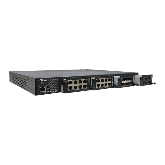
C (If use 10G SFP module then operating temperature is -20 ~ 60 C), RGS-PR9000 can be managed centrally and conveniently via Open-Vision, web browsers, Telnet and console (CLI) configuration, making it one of the most reliable choice for highly-managed and Fiber Ethernet power substation and rolling stock application. -
Page 8: Hardware Specifications
RGS-PR9000 Series User Manual Supports IP-based bandwidth management Supports application-based QoS management Supports Device Binding security function Supports DOS/DDOS auto prevention Supports IGMP v2/v3 (IGMP snooping support) to filter multicast traffic Supports SNMP v1/v2c/v3 & RMON & 802.1Q VLAN network management ... -
Page 9: Hardware Overview
ORing provides four 10 Gigabit modules and six Gigabit Ethernet modules for you to make the best of the RGS-PR9000 switch in line with your demand. For applications requiring long-distance data transmission, ORing also provides several fiber modules to meet your needs. -
Page 10: Led
RGS-PR9000 Series User Manual 4-port fiber module with 4x100Base-FX ST SWM-04FX-MM/SS-ST Fiber ports 6-port fiber module with 6x100Base-FX LC SWM-06FX-MM/SS-LC Fiber ports 6-port fiber module with 6x100Base-FX SWM-06FX-MM/SS-MTRJ MTRJ Fiber ports 1. System indication LEDs: PWR/PWR1/PWR2/R.M/Ring/Fault/DEF 2. Port status LEDs: LINK/SPD/FDX/port number 3. -
Page 11: Rear Panel
RGS-PR9000 Series User Manual Fast blinking Ring disabled Errors (power failure or port Fault Amber malfunctioning) Green System reset to default Green Accessed remotely Green Port link up Green Blinking Data transmitted Amber Port works under full duplex. 2.2 Rear Panel On the rear panel of the switch sit two panel module slots and one terminal block. -
Page 12: Hardware Installation
RGS-PR9000 Series User Manual ardware Installation 3.1 Rack-mount Installation The switch comes with two rack-mount kits to allow you to fasten the switch to a rack in any environments. Follow the following steps to install the switch to a rack. -
Page 13: Module Installation
Step 3: Switch on the power of the switch 3.2.2 SFP Module Each RGS-PR9000 series switch supports maximum three SFP modules, giving you a total of 24 SFP ports. Follow the steps bellows for installation. Step 1: Switch off the power of the switch. -
Page 14: Sfp+ Module
3.2.3 10G SFP+ Module Each RGS-PR9000 series switch supports one 10G SFP+ module, giving you a total of 4 10G ports. Follow the steps bellows for installation. ORing provides several 10G module options, including SWM-02GP+, SWM-04GP+, SWM-22GTP+, and SWM-40GT+. The module can be plugged into the 10-Gigabit Ethernet port of the switch and links the switch with a fiber-optic network. -
Page 15: Power Module
RGS-PR9000 Series User Manual 3.2.4 Power Module Each RGS-PR9000 series switch supports maximum two power modules. Follow the steps bellows for installation. Step 1: Switch off the power of the switch. Step 2: Insert the modules in Power 1 and 2 slots respectively. -
Page 16: Grounding
Cables 1000/100BASE-TX/10BASE-T Pin Assignments RGS-PR9000 comes with standard Ethernet ports. According to the link type, the switch uses CAT 3, 4, 5,5e UTP cables to connect to any other network devices (PCs, servers, switches, routers, or hubs). Please refer to the following table for cable specifications. - Page 17 BI_DB- BI_DD+ BI_DD- The RGS-PR9000 series switches support auto MDI/MDI-X operation. You can use a cable to connect the switch to a PC. The table below shows the 10BASE-T/ 100BASE-TX MDI and MDI-X port pin outs. ORing Industrial Networking Corp...
- Page 18 Note: “+” and “-” signs represent the polarity of the wires that make up each wire pair. RS-232 port wiring RGS-PR9000 can be managed via console ports using a RS-232 cable which can be found in the package. You can connect the port to a PC via the RS-232 cable with a DB-9 female connector.
-
Page 19: Sfp
RGS-PR9000 Series User Manual 3.4.2 The switch comes with fiber optical ports that can connect to other devices using SFP modules. The fiber optical ports are in multi-mode (0 to 550M, 850 nm with 50/125 µm, 62.5/125 µm fiber) and single-mode with LC connectors. Please remember that the TX port of Switch A should be connected to the RX port of Switch B. - Page 20 RGS-PR9000 Series User Manual O-Ring Coupling Ring If you already have two O-Ring topologies and would like to connect the rings, you can form them into a couping ring. All you need to do is select two switches from each ring to be connected, for example, switch A and B from Ring 1 and switch C and D from ring 2.
- Page 21 RGS-PR9000 Series User Manual primary path connection fails. RSTP Backup Path Main Path Switch B Switch A O-Ring O-Chain When connecting multiple O-Rings to meet your expansion demand, you can create an O-Chain topology through the following steps. 1. Select two switches from the chain (Switch A & B) that you want to connect to the O-Ring and connect them to the switches in the ring (Switch C &...
-
Page 22: Redundancy
4.1 O-Ring 4.1.1 Introduction O-Ring is ORing's proprietary redundant ring technology, with recovery time of less than 10 milliseconds and up to 250 nodes. The ring protocols identify one switch as the master of the network, and then automatically block packets from traveling through any of the network’s redundant loops. - Page 23 RGS-PR9000 Series User Manual Label Description Check to enable O-Ring topology. Redundant Ring Only one ring master is allowed in a ring. However, if more than one switches are set to enable Ring Master, the switch Ring Master with the lowest MAC address will be the active ring master and the others will be backup masters.
-
Page 24: O-Chain
RGS-PR9000 Series User Manual 4.2 O-Chain 4.2.1 Introduction O-Chain is ORing’s revolutionary network redundancy technology which enhances network redundancy for any backbone networks, providing ease-of-use and maximum fault-recovery swiftness, flexibility, compatibility, and cost-effectiveness in a set of network redundancy topologies. The self-healing Ethernet technology designed for distributed and complex industrial networks enables the network to recover in less than 10ms for up to 250 switches if at any time a segment of the chain fails. -
Page 25: Mrp
RGS-PR9000 Series User Manual Label Description Enable Check to enable O-Chain function Ring Port The first port connecting to the ring Ring Port The second port connecting to the ring Edge Port An O-Chain topology must begin with edge ports. The ports with a smaller switch MAC address will serve as the backup link and RM LED will light up. -
Page 26: Stp/Rstp/Mstp
RGS-PR9000 Series User Manual 4.4 STP/RSTP/MSTP 4.4.1 STP/RSTP STP (Spanning Tree Protocol), and its advanced versions RSTP (Rapid Spanning Tree Protocol) and MSTP (Multiple Spanning Tree Protocol), are designed to prevent network loops and provide network redundancy. Network loops occur frequently in large networks as when two or more paths run to the same destination, broadcast packets may get in to an infinite loop and hence causing congestion in the network. -
Page 27: Stp Port Status
RGS-PR9000 Series User Manual STP Port Status This page displays the STP port status for the currently selected switch. Label Description The switch port number to which the following settings will be Port applied. The current STP port role of the CIST port. The values include: CIST Role AlternatePort, BackupPort, RootPort, and DesignatedPort. - Page 28 RGS-PR9000 Series User Manual Label Description The switch port number to which the following settings will be Port applied. The number of RSTP configuration BPDUs received/transmitted RSTP on the port number legacy configuration BPDUs received/transmitted on the port The number of (legacy) topology change notification BPDUs...
-
Page 29: Mstp
RGS-PR9000 Series User Manual is considered valid. The range of valid values is 6 to 40 seconds, and Max Age must be <= (FwdDelay-1)*2. This defines the initial value of remaining hops for MSTI information generated at the boundary of an MSTI region. It... - Page 30 RGS-PR9000 Series User Manual Label Description The switch port number of the corresponding STP CIST (and Port MSTI) port Configures the path cost incurred by the port. Auto will set the path cost according to the physical link speed by using the 802.1D-recommended values.
- Page 31 RGS-PR9000 Series User Manual Mapping This page allows you to examine and change the configurations of current STP MSTI bridge instance. Label Description The name which identifies the VLAN to MSTI mapping. Bridges must share the name and revision (see below), as well as the...
- Page 32 RGS-PR9000 Series User Manual mapped to one MSTI. An unused MSTI will be left empty (ex. without any mapped VLANs). Click to save changes. Click to undo any changes made locally and revert to previously saved values. Priority This page allows you to examine and change the configurations of current STP MSTI bridge instance priority.
-
Page 33: Cist
RGS-PR9000 Series User Manual 4.4.3 CIST With the ability to cross regional boundaries, CIST is used by MSTP to communicate with other MSTP regions and with any RSTP and STP single-instance spanning trees in the network. Any boundary port, that is, if it is connected to another region, will automatically belongs solely to CIST, even if it is assigned to an MSTI. -
Page 34: Fast Recovery
RGS-PR9000 Series User Manual operEdge state when a port is initialized). Check to enable the bridge to detect edges at the bridge port AutoEdge automatically. This allows operEdge to be derived from whether BPDUs are received on the port or not. - Page 35 RGS-PR9000 Series User Manual different priorities will be backup ports. Label Description Active Activates fast recovery mode port Ports can be set to 12 priorities. Only the port with the highest priority will be the active port. 1st Priority is the highest.
-
Page 36: Management
RGS-PR9000 Series User Manual anagement The switch can be controlled via a built-in web server which supports Internet Explorer (Internet Explorer 5.0 or above versions) and other Web browsers such as Chrome. Therefore, you can manage and configure the switch easily and remotely. You can also upgrade firmware via a web browser. -
Page 37: Basic Settings
RGS-PR9000 Series User Manual After logging in, you can see the information of the switch as below. On the right hand side of the management interface shows links to various settings. You can click on the links to access the configuration pages of different functions. -
Page 38: System Information
RGS-PR9000 Series User Manual 5.1.1 System Information This page shows the general information of the switch. Label Description An administratively assigned name for the managed node. By convention, this is the node's fully-qualified domain name. A domain name is a text string consisting of alphabets (A-Z, a-z), System Name digits (0-9), and minus sign (-). -
Page 39: Admin & Password
RGS-PR9000 Series User Manual 5.1.2 Admin & Password This page allows you to configure the system password required to access the web pages or log in from CLI. Label Description Old Password The existing password. If this is incorrect, you cannot set the new password. -
Page 40: Ip Settings
RGS-PR9000 Series User Manual Label Description Client The management client for which the configuration below applies. Authentication Method can be set to one of the following values: None: authentication is disabled and login is not possible. Authentication Local: local user database on the switch is used for Method authentication. -
Page 41: Ipv6 Settings
RGS-PR9000 Series User Manual and it will be displayed in this column. The default IP is 192.168.10.1. Assigns the subnet mask of the IP address. If DHCP client IP Mask function is enabled, you do not need to assign the subnet mask. -
Page 42: Https
RGS-PR9000 Series User Manual groups of contiguous zeros; but it can appear only once. It can also represent a legally valid IPv4 address. For example, '::192.1.2.34'. Provides the IPv6 prefix of the switch. The allowed range is 1 to Prefix 128. -
Page 43: Ssh
RGS-PR9000 Series User Manual Click to undo any changes made locally and revert to previously saved values 5.1.7 SSH You can configure the SSH mode in the following page. Label Description Indicates the selected SSH mode. The modes include: Mode Enabled: enable SSH. - Page 44 RGS-PR9000 Series User Manual Label Description The switch port number to which the following settings will be Port applied. Indicates the selected LLDP mode Rx only: the switch will not send out LLDP information, but LLDP information from its neighbors will be analyzed.
- Page 45 RGS-PR9000 Series User Manual 8. Station Only 9. Reserved When a capability is enabled, a (+) will be displayed. If the capability is disabled, a (-) will be displayed. Management The neighbor's address which can be used to help network Address management.
- Page 46 RGS-PR9000 Series User Manual Total Neighbors Shows the number of LLDP frames dropped due to full entry table Entries Dropped Total Neighbors Shows the number of entries deleted due to expired time-to-live Entries Aged Out Local Counters Label Description Local Port...
-
Page 47: Modbus Tcp
RGS-PR9000 Series User Manual 5.1.9 Modbus TCP This page shows Modbus TCP support of the switch. (For more information regarding Modbus, http://www.modbus.org/ please visit Label Description Mode Shows the existing status of the Modbus TCP function 5.1.10 Backup/Restore Configurations You can save/view or load switch configurations. The configuration file is in XML format. -
Page 48: Dhcp Server
RGS-PR9000 Series User Manual 5.2 DHCP Server The switch provides DHCP server functions. By enabling DHCP, the switch will become a DHCP server and dynamically assigns IP addresses and related IP information to network clients. 5.2.1 Basic Settings This page allows you to set up DHCP settings for the switch. You can check the Enabled checkbox to activate the function. -
Page 49: Relay Agent
RGS-PR9000 Series User Manual the IP address that has previously been assigned to the connected device. 5.2.4 Relay Agent DHCP relay is used to forward and transfer DHCP messages between the clients and the server when they are not in the same subnet domain. You can configure the function in this page. - Page 50 RGS-PR9000 Series User Manual represent the VLAN ID, and the fifth and sixth characters are the module ID. In stand-alone devices, the module ID always equals to 0; in stacked devices, it means switch ID. The last two characters are the port number. For example, "00030108"...
-
Page 51: Port Setting
RGS-PR9000 Series User Manual Label Description Transmit to Sever The number of packets relayed from the client to the server Transmit Error The number of packets with errors when being sent to clients Receive from Server The number of packets received from the server... -
Page 52: Port Control
RGS-PR9000 Series User Manual 5.3.1 Port Control This page shows current port configurations. Ports can also be configured here. Label Description The switch port number to which the following settings will be Port applied. The current link state is shown by different colors. Green indicates Link the link is up and red means the link is down. -
Page 53: Port Trunk
RGS-PR9000 Series User Manual You can enter the maximum frame size allowed for the switch port Maximum Frame in this column, including FCS. The allowed range is 1518 bytes to 9600 bytes. Shows the current power consumption of each port in percentage. - Page 54 RGS-PR9000 Series User Manual box to enable the IP address, or uncheck to disable. By default, IP Address is enabled. TCP/UDP Port Calculates the destination port of the frame. You can check this Number box to enable the TCP/UDP port number, or uncheck to disable.
-
Page 55: Lacp System Status
RGS-PR9000 Series User Manual Label Description Port Indicates the ID of each aggregation group. Normal indicates there is no aggregation. Only one group ID is valid per port. LACP Enabled Lists each switch port for each group ID. Check to include a port in an aggregation, or clear the box to remove the port from the aggregation. -
Page 56: Lacp Status
RGS-PR9000 Series User Manual Label Description Aggr ID The aggregation ID is associated with the aggregation instance. For LLAG, the ID is shown as 'isid:aggr-id' and for GLAGs as 'aggr-id' Partner System ID System ID (MAC address) of the aggregation partner... -
Page 57: Lacp Statistics
RGS-PR9000 Series User Manual port cannot join in the aggregation group unless other ports are removed. The LACP status is disabled. The key assigned to the port. Only ports with the same key can be aggregated Aggr ID The aggregation ID assigned to the aggregation group Partner System ID The partner’s system ID (MAC address) -
Page 58: Loop Gourd
RGS-PR9000 Series User Manual Click to refresh the page immediately Check to enable an automatic refresh of the page at regular intervals Click to clear the counters for all ports 5.3.4 Loop Gourd This feature prevents loop attack. When receiving loop packets, the port will be disabled automatically, preventing the loop attack from affecting other network devices. -
Page 59: Vlan
RGS-PR9000 Series User Manual Label Description Port Switch port number Enable Activate loop protection functions (as a whole) Action Configures the action to take when a loop is detected. Valid values include Shutdown Port, Shutdown Port, and Log or Log Only. -
Page 60: Port Configurations
RGS-PR9000 Series User Manual 5.4.2 Port Configurations This page allows you to set up VLAN ports individually. Label Description Ethertype for This field specifies the Ether type used for custom S-ports. This is customer S-Ports a global setting for all custom S-ports. - Page 61 RGS-PR9000 Series User Manual processing. If the port only accepts tagged frames, untagged frames received on the port will be discarded. By default, the field is set to All. The allowed values are None or Specific. This parameter affects VLAN ingress and egress processing.
- Page 62 RGS-PR9000 Series User Manual for 802.1QinQ 1. if the tagged frame contains a TPID of frame after egressing (double tag). 0x8100, it will become a double-tag frame and will also be affected by will be forwarded. the Egress Rule. 2. if the TPID of tagged frame is not 0x8100 (ex.
- Page 63 RGS-PR9000 Series User Manual ORing Industrial Networking Corp...
- Page 64 RGS-PR9000 Series User Manual ORing Industrial Networking Corp...
- Page 65 RGS-PR9000 Series User Manual Examples of VLAN Settings VLAN Access Mode: Switch Port 7 is VLAN Access mode = Untagged 20 Port 8 is VLAN Access mode = Untagged 10 Below are the switch settings. ORing Industrial Networking Corp...
- Page 66 RGS-PR9000 Series User Manual VLAN 1Q Trunk Mode: Switch Port 1 = VLAN 1Qtrunk mode = tagged 10, 20 Port 2 = VLAN 1Qtrunk mode = tagged 10, 20 Below are the switch settings. ORing Industrial Networking Corp...
- Page 67 RGS-PR9000 Series User Manual VLAN Hybrid Mode: Port 1 VLAN Hybrid mode = untagged 10 Tagged 10, 20 Below are the switch settings. ORing Industrial Networking Corp...
- Page 68 RGS-PR9000 Series User Manual VLAN QinQ Mode: VLAN QinQ mode is usually adopted when there are unknown VLANs, as shown in the figure below VLAN “X” = Unknown VLAN 9000 Series Port 1 VLAN Settings: VLAN ID Settings When setting the management VLAN, only the same VLAN ID port can be used to control the switch.
-
Page 69: Private Vlan
RGS-PR9000 Series User Manual 9000 ies VLAN Settings: 5.4.3 Private VLAN The private VLAN membership configuration for the switch can be monitored and modified here. Private VLANs can be added or deleted here. Port members of each private VLAN can be added or removed here. - Page 70 RGS-PR9000 Series User Manual MAC Address The MAC address for the entry. A row of check boxes for each port is displayed for each private VLAN ID. You can check the box to include a port in a private Port Members VLAN.
-
Page 71: Snmp
RGS-PR9000 Series User Manual 5.5 SNMP 5.5.1 SNMP System Configurations Label Description Indicates existing SNMP mode. Possible modes include: Mode Enabled: enable SNMP mode Disabled: disable SNMP mode Indicates the supported SNMP version. Possible versions include: SNMP v1: supports SNMP version 1. - Page 72 RGS-PR9000 Series User Manual Label Description Indicates existing SNMP trap mode. Possible modes include: Trap Mode Enabled: enable SNMP trap mode Disabled: disable SNMP trap mode Indicates the supported SNMP trap version. Possible versions include: Trap Version SNMP v1: supports SNMP trap version 1...
-
Page 73: Snmp Community Configurations
RGS-PR9000 Series User Manual Disabled: disable SNMP trap authentication failure Indicates the SNMP trap link-up and link-down mode. Possible Trap Link-up and modes include: Link-down Enabled: enable SNMP trap link-up and link-down mode Disabled: disable SNMP trap link-up and link-down mode Indicates the SNMP trap inform mode. -
Page 74: Snmp User Configurations
RGS-PR9000 Series User Manual Label Description Delete Check to delete the entry. It will be deleted during the next save. Indicates the community access string to permit access to SNMPv3 Community agent. The allowed string length is 1 to 32, and only ASCII characters from 33 to 126 are allowed. -
Page 75: Snmp Group Configurations
RGS-PR9000 Series User Manual SNMP engine with which this user can communicate. In other words, if user engine ID is the same as system engine ID, then it is local user; otherwise it's remote user. A string identifying the user name that this entry should belong to. -
Page 76: Snmp View Configurations
RGS-PR9000 Series User Manual This page allows you to configure SNMPv3 group table. The entry index keys are Security Model and Security Name. Label Description Delete Check to delete the entry. It will be deleted during the next save. Indicates the security model that this entry should belong to. Possible... -
Page 77: Snmp Access Configurations
RGS-PR9000 Series User Manual Label Description Delete Check to delete the entry. It will be deleted during the next save. A string identifying the view name that this entry should belong to. View Name The allowed string length is 1 to 32, and only ASCII characters from 33 to 126 are allowed. -
Page 78: Traffic Prioritization
RGS-PR9000 Series User Manual v2c: Reserved for SNMPv2c. usm: User-based Security Model (USM). Indicates the security model that this entry should belong to. Possible security models include: Security Level NoAuth, NoPriv: no authentication and no privacy Auth, NoPriv: Authentication and no privacy... -
Page 79: Port Classification
RGS-PR9000 Series User Manual Label Description The settings in a particular row apply to the frame type listed here: Frame Type unicast, multicast, or broadcast. Enable or disable the storm control status for the given frame Status type. The rate unit is packet per second (pps), configure the rate as 1K, Rate 2K, 4K, 8K, 16K, 32K, 64K, 128K, 256K, 512K, or 1024K. - Page 80 RGS-PR9000 Series User Manual shown below. Otherwise the frame is classified to the default QoS class. PCP value: 0 1 2 3 4 5 6 7 QoS class: 1 0 2 3 4 5 6 7 If the port is VLAN aware, the frame is tagged, and Tag Class is enabled, then the frame is classified to a QoS class that is mapped from the PCP and DEI value in the tag.
-
Page 81: Port Tag Remaking
RGS-PR9000 Series User Manual default QoS class and DP level. DSCP Based Click to enable DSCP Based QoS Ingress Port Classification 5.6.3 Port Tag Remaking This page provides an overview of QoS Egress Port Tag Remarking for all switch ports. - Page 82 RGS-PR9000 Series User Manual Label Description Shows the list of ports for which you can configure DSCP Ingress Port and Egress settings. In Ingress settings you can change ingress translation and classification settings for individual ports. Ingress There are two configuration parameters available in Ingress: 1.
-
Page 83: Port Policing
RGS-PR9000 Series User Manual Enable: rewrite enabled without remapping Remap DP Unaware: DSCP from the analyzer is remapped and the frame is remarked with a remapped DSCP value. The remapped DSCP value is always taken from the 'DSCP Translation->Egress Remap DP0' table. -
Page 84: Queue Policing
RGS-PR9000 Series User Manual 5.6.6 Queue Policing This page allows you to configure Queue Policer settings for all switch ports. Label Description Port The port number for which the configuration below applies. Enable(E) Check to enable queue policer for individual switch ports Configures the rate of each queue policer. -
Page 85: Qos Egress Port Scheduler And Shapers
RGS-PR9000 Series User Manual 5.6.7 QoS Egress Port Scheduler and Shapers This page allows you to configure Scheduler and Shapers for a specific port. Strict Priority Label Description Controls whether the scheduler mode is Strict Priority or Scheduler Mode Weighted on this switch port... - Page 86 RGS-PR9000 Series User Manual Queue Shaper Allows the queue to use excess bandwidth Excess Port Shaper Enable Check to enable port shaper for individual switch ports Configures the rate of each port shaper. The default value is 500 Port Shaper Rate This value is restricted to 100 to 1000000 when the Unit is kbps, and it is restricted to 1 to 3300 when the Unit is Mbps.
-
Page 87: Port Scheduled
RGS-PR9000 Series User Manual Enable Configures the rate of each queue shaper. The default value is Queue Shaper Rate 500. This value is restricted to 100 to 1000000 when the Unit is kbps, and it is restricted to 1 to 3300 when the Unit is Mbps. -
Page 88: Port Shaping
RGS-PR9000 Series User Manual 5.6.9 Port Shaping This page provides an overview of QoS Egress Port Shapers for all switch ports. Label Description The switch port number to which the following settings will be Port applied. Click on the port number to configure the shapers Mode Shows disabled or actual queue shaper rate - e.g. -
Page 89: Dscp Translation
RGS-PR9000 Series User Manual 5.6.11 DSCP Translation This page allows you to configure basic QoS DSCP translation settings for all switches. DSCP translation can be done in Ingress or Egress. Label Description Maximum number of supported DSCP values is 64 and valid DSCP DSCP value ranges from 0 to 63. -
Page 90: Qos Control List
RGS-PR9000 Series User Manual Label Description QoS Class Actual QoS class Actual Drop Precedence Level DSCP Select the classified DSCP value (0-63) 5.6.13 QoS Control List This page allows you to edit or insert a single QoS control entry at a time. A QCE consists of several parameters. - Page 91 RGS-PR9000 Series User Manual Tag: value of tag, can be Any, Untag or Tag. VID: valid value of VLAN ID, can be any value from 1 to 4095 Any: user can enter either a specific value or a range of VIDs.
-
Page 92: Qos Counters
RGS-PR9000 Series User Manual or AF11-AF43. IP Fragment: Ipv4 frame fragmented options include 'yes', 'no', and 'any'. Sport Source TCP/UDP Port: (0-65535) or Any, specific value or port range applicable for IP protocol UDP/TCP Dport Destination TCP/UDP Port: (0-65535) or Any, specific value or... -
Page 93: Qcl Status
RGS-PR9000 Series User Manual Label Description The switch port number to which the following settings will be Port applied. There are 8 QoS queues per port. Q0 is the lowest priority Rx / Tx The number of received and transmitted packets per queue 5.6.15 QCL Status... -
Page 94: Multicast
RGS-PR9000 Series User Manual DPL: Drop Precedence Level; if a frame matches the QCE, then DP level will set to a value displayed under DPL column. DSCP: if a frame matches the QCE, then DSCP will be classified with the value displayed under DSCP column. -
Page 95: Vlan Configurations Of Igmp Snooping
RGS-PR9000 Series User Manual If an aggregation member port is selected as a router port, the whole aggregation will act as a router port. Fast Leave Check to enable fast leave on the port 5.7.2 VLAN Configurations of IGMP Snooping Each page shows up to 99 entries from the VLAN table, with a default value of 20, selected by the Entries Per Page input field. -
Page 96: Igmp Snooping Status
RGS-PR9000 Series User Manual IGMP Querier Check to enable the IGMP Querier in the VLAN 5.7.3 IGMP Snooping Status This page provides IGMP snooping status. Label Description VLAN ID The VLAN ID of the entry Querier Version Active Querier version... -
Page 97: Security
RGS-PR9000 Series User Manual first by VLAN ID, and then by group. Label Description VLAN ID The VLAN ID of the group Groups The group address of the group displayed Port Members Ports under this group 5.8 Security 5.8.1 Remote Control Security Configurations Remote Control Security allows you to limit the remote access to the management interface. -
Page 98: Device Binding
RGS-PR9000 Series User Manual SNMP Check to enable management via a SNMP interface Delete Check to delete entries 5.8.2 Device Binding This page provides device binding configurations. Device binding is a powerful way to monitor devices and network security. Label Description Indicates the device binding operation for each port. -
Page 99: Advanced Configurations
RGS-PR9000 Series User Manual Low: the stream is getting low. DDoS Prevention Check to enable DDOS prevention. When enabled, the switch will Acton monitor the device against DDOS attacks. Indicates DDOS prevention status. Possible statuses are: ---: disable DDoS Prevention... - Page 100 RGS-PR9000 Series User Manual Label Description Link Change Disables or enables the port Only log it Simply sends logs to the log server Shunt Down the Disables the port Port Reboot Device Disables or enables PoE power DDoS Prevention This page provides DDOS Prevention configurations. The switch can monitor ingress packets, and perform actions when DDOS attack occurred on this port.
- Page 101 RGS-PR9000 Series User Manual Low: low sensibility Normal: normal sensibility Medium: medium sensibility High: high sensibility Indicates the types of DDoS attack packets to be monitored. Possible types are: RX Total: all ingress packets RX Unicast: unicast ingress packets Packet Type...
-
Page 102: Device Description
RGS-PR9000 Series User Manual Device Description This page allows you to configure device description settings. Label Description Indicates device types. Possible types are: --- (no specification), IP Device Type Camera, IP Phone, Access Point, PC, PLC, and Network Video Recorder Indicates location information of the device. -
Page 103: Acl
RGS-PR9000 Series User Manual Label Description Mode Enables or disables stream monitoring of the port Indicates the action to take when the stream gets low. Possible actions are: Action ---: no action Log it: simply logs the event 5.8.3 ACL Ports This page allows you to configure the ACL parameters (ACE) of each switch port. -
Page 104: Rate Limiters
RGS-PR9000 Series User Manual Specifies the shutdown operation of this port. The allowed values are: Shutdown Enabled: if a frame is received on the port, the port will be disabled. Disabled: port shut down is disabled. The default value is Disabled. - Page 105 RGS-PR9000 Series User Manual Label Description Indicates the ingress port to which the ACE will apply. Any: the ACE applies to any port Port n: the ACE applies to this port number, where n is the number of the Ingress Port switch port.
- Page 106 RGS-PR9000 Series User Manual Please note that system log memory capacity and logging rate is limited. Specifies the shutdown operation of the ACE. The allowed values are: Shutdown Enabled: if a frame matches the ACE, the ingress port will be disabled.
- Page 107 RGS-PR9000 Series User Manual Label Description Specifies the VLAN ID filter for the ACE Any: no VLAN ID filter is specified (VLAN ID filter status is VLAN ID Filter "don't-care"). Specific: if you want to filter a specific VLAN ID with the ACE, choose this value.
- Page 108 RGS-PR9000 Series User Manual for defining ICMP parameters will appear. For more details of these fields, please refer to the help file. UDP: selects UDP to filter IPv4 UDP protocol frames. Extra fields for defining UDP parameters will appear. For more details of these fields, please refer to the help file.
- Page 109 RGS-PR9000 Series User Manual When Host or Network is selected for the source IP filter, you can SIP Address enter a specific SIP address in dotted decimal notation. When Network is selected for the source IP filter, you can enter a SIP Mask specific SIP mask in dotted decimal notation.
- Page 110 RGS-PR9000 Series User Manual Reply: frame must have ARP Reply or RARP Reply OP flag. Specifies the sender IP filter for the ACE Any: no sender IP filter is specified (sender IP filter is "don't-care"). Host: sender IP filter is set to Host. Specify the sender IP address in Sender IP Filter the SIP Address field that appears.
- Page 111 RGS-PR9000 Series User Manual the (PLN) is equal to IPv4 (0x04) must not match this entry. 1: ARP/RARP frames where the HLN is equal to Ethernet (0x06) and the (PLN) is equal to IPv4 (0x04) must match this entry. Any: any value is allowed ("don't-care").
- Page 112 RGS-PR9000 Series User Manual "don't-care"). Specific: if you want to filter a specific ICMP code filter with the ACE, you can enter a specific ICMP code value. A field for entering an ICMP code value appears. When Specific is selected for the ICMP code filter, you can enter a ICMP Code Value specific ICMP code value.
- Page 113 RGS-PR9000 Series User Manual value. Specifies the TCP/UDP destination filter for the ACE Any: no TCP/UDP destination filter is specified (TCP/UDP destination filter status is "don't-care"). Specific: if you want to filter a specific TCP/UDP destination filter TCP/UDP with the ACE, you can enter a specific TCP/UDP destination value. A Destination Filter field for entering a TCP/UDP destination value appears.
-
Page 114: Aaa
RGS-PR9000 Series User Manual Any: any value is allowed ("don't-care"). Specifies the TCP ACK ("acknowledgment field significant") value for the ACE 0: TCP frames where the ACK field is set must not be able to match TCP ACK this entry. - Page 115 RGS-PR9000 Series User Manual be queried up to 3 times before it is considered to be dead. The dead time, which can be set to a number between 0 and 3600 seconds, is the period during which the switch will not send new requests to a server that has failed to respond to a previous request.
- Page 116 RGS-PR9000 Series User Manual Label Description The RADIUS accounting server number for which the configuration below applies. Enabled Check to enable the RADIUS accounting server The IP address or hostname of the RADIUS accounting server. IP IP Address address is expressed in dotted decimal notation.
- Page 117 RGS-PR9000 Series User Manual notation) of the server The current status of the server. This field has one of the following values: Disabled: the server is disabled. Not Ready: the server is enabled, but IP communication is not yet up and running.
- Page 118 RGS-PR9000 Series User Manual temporarily been disabled, but will be re-enabled when the dead-time expires. The number of seconds left before this occurs is displayed in parentheses. This state is only reachable when more than one server is enabled. Authentication and Accounting Server Statistics The statistics map closely to those specified in RFC4668 - RADIUS Authentication Client MIB.
- Page 119 RGS-PR9000 Series User Manual This section contains information about the state of the server and the latest round-trip time. Other Info Label Description RADIUS accounting server packet counters. There are five ‘receive’ and four ‘transmit’ counters. Packet Counters ORing Industrial Networking Corp...
-
Page 120: Nas (802.1X)
RGS-PR9000 Series User Manual This section contains information about the state of the server and the latest round-trip time. Other Info 5.8.6 NAS (802.1x) This page allows you to configure the IEEE 802.1X and MAC-based authentication system and port settings. - Page 121 RGS-PR9000 Series User Manual supplicant and the authentication server are using, or how many information exchange frames are needed for a particular method. The switch simply encapsulates the EAP part of the frame into the relevant type (EAPOL or RADIUS) and forwards it.
- Page 122 RGS-PR9000 Series User Manual authentication, and that the clients do npt need special supplicant software to authenticate. The disadvantage is that MAC addresses can be spoofed by malicious users, equipment whose MAC address is a valid RADIUS user can be used by anyone, and only the MD5-Challenge method is supported.
- Page 123 RGS-PR9000 Series User Manual Reauthenti Determines the period, in seconds, after which a connected client must be cation re-authenticated. This is only active if the Reauthentication Enabled Period checkbox is checked. Valid range of the value is 1 to 3600 seconds.
- Page 124 RGS-PR9000 Series User Manual Force Unauthorized In this mode, the switch will send one EAPOL Failure frame when the port link is up, and any client on the port will be disallowed network access. Port-based 802.1X In an 802.1X network environment, the user is called the supplicant, the switch is the authenticator, and the RADIUS server is the authentication server.
- Page 125 RGS-PR9000 Series User Manual authenticated on a port, the whole port is opened for network traffic. This allows other clients connected to the port (for instance through a hub) to piggy-back on the successfully authenticated client and get network access even though they are not authenticated individually.
- Page 126 RGS-PR9000 Series User Manual wake up any supplicants that might be on the port. The maximum number of supplicants that can be attached to a port can be limited using the Port Security Limit Control functionality. MAC-based Auth. Unlike port-based 802.1X, MAC-based authentication is not a standard, but merely a best-practices method adopted by the industry.
-
Page 127: Nas Status
RGS-PR9000 Series User Manual Unauthorized: the port is in Force Unauthorized or a single-supplicant mode and the supplicant is not successfully authorized by the RADIUS server. X Auth/Y Unauth: the port is in a multi-supplicant mode. Currently X clients are authorized and Y are unauthorized. - Page 128 RGS-PR9000 Series User Manual details regarding each value. The source MAC address carried in the most recently received EAPOL frame for EAPOL-based authentication, and the most Last Source recently received frame from a new client for MAC-based authentication. The user name (supplicant identity) carried in the most recently...
- Page 129 RGS-PR9000 Series User Manual These backend (RADIUS) frame counters are available for the following administrative states: • 802.1X • MAC-based Auth. Backend Server Counters Information about the last supplicant/client that attempts to Last authenticate. This information available for following Supplicant/Clien administrative states: •...
-
Page 130: Alerts
RGS-PR9000 Series User Manual 5.9 Alerts 5.9.1 Fault Alarm When any selected fault event happens, the Fault LED on the switch panel will light up and the electric relay will signal at the same time. 5.9.2 System Warning SYSLOG Setting The SYSLOG is a protocol that transmits event notifications across networks. -
Page 131: Smtp Setting
RGS-PR9000 Series User Manual Label Description Server Mode Indicates existing server mode. When the mode operation is enabled, the syslog message will be sent to syslog server. The syslog protocol is based on UDP communications and received on UDP port 514 and... - Page 132 RGS-PR9000 Series User Manual Label Description E-mail Alarm Enables or disables transmission of system warnings by e-mail Sender E-mail SMTP server IP address Address Mail Subject Subject of the mail Authentication Username: the authentication username Password: the authentication password ...
-
Page 133: Monitor And Diag
RGS-PR9000 Series User Manual Label Description System Cold Start Sends out alerts when the system is restarted Power Status Sends out alerts when power is up or down SNMP Authentication Failure Sends out alert when SNMP authentication fails O-Ring Topology Change Sends out alerts when O-Ring topology changes ... - Page 134 RGS-PR9000 Series User Manual Aging Configuration By default, dynamic entries are removed from the MAC after 300 seconds. This removal is called aging. You can configure aging time by entering a value in the box below in seconds; for example, Age Time seconds.
- Page 135 RGS-PR9000 Series User Manual Static MAC Table Configurations The static entries in the MAC table are shown in this table. The static MAC table can contain up to 64 entries. The entries are for the whole stack, not for individual switches. The MAC table is sorted first by VLAN ID and then by MAC address.
-
Page 136: Port Statistics
RGS-PR9000 Series User Manual - assume the value of the first displayed entry, allows for continuous refresh with the same start address. will use the last entry of the currently displayed VLAN/MAC address pairs as a basis for the next lookup. When it reaches the end, the text "no more entries" is shown in the displayed table. -
Page 137: Detailed Statistics
RGS-PR9000 Series User Manual Label Description The switch port number to which the following settings will be Port applied. Packets The number of received and transmitted packets per port Bytes The number of received and transmitted bytes per port The number of frames received in error and the number of... -
Page 138: Port Mirroring
RGS-PR9000 Series User Manual Label Description Rx and Tx Packets The number of received and transmitted (good and bad) packets The number of received and transmitted (good and bad) bytes, Rx and Tx Octets including FCS, except framing bits The number of received and transmitted (good and bad) unicast... -
Page 139: System Log Information
RGS-PR9000 Series User Manual Label Description Port The switch port number to which the following settings will be applied. Drop-down list for selecting a mirror mode. Rx only: only frames received on this port are mirrored to the mirror port. -
Page 140: Cable Diagnostics
RGS-PR9000 Series User Manual Label Description The ID (>= 1) of the system log entry The level of the system log entry. The following level types are supported: Info: provides general information Level Warning: provides warning for abnormal operation Error: provides error message... -
Page 141: Sfp Monitor
RGS-PR9000 Series User Manual Press to run the diagnostics. This will take approximately 5 seconds. If all ports are selected, this can take approximately 15 seconds. When completed, the page refreshes automatically, and you can view the cable diagnostics results in the cable status table. Note that VeriPHY diagnostics is only accurate for cables 7 - 140 meters long. -
Page 142: Ping
RGS-PR9000 Series User Manual 5.10.7 Ping This page allows you to issue ICMP PING packets to troubleshoot IP connectivity issues After you press , five ICMP packets will be transmitted, and the sequence number and roundtrip time will be displayed upon reception of a reply. The page refreshes automatically until responses to all packets are received, or until a timeout occurs PING6 server ::10.10.132.20... -
Page 143: Synchronization
RGS-PR9000 Series User Manual PING6 server ::192.168.10.1 sendto sendto sendto sendto sendto Sent 5 packets, received 0 OK, 0 bad 5.11 Synchronization MAC-based Authentication This page allows you to configure and examine current PTP clock settings. PTP External Clock Mode... - Page 144 RGS-PR9000 Series User Manual Frequency The range of values is 1 - 25000000 (1 - 25MHz). PTP Clock Configurations Label Description Delete Check this box and click Save to delete the clock instance Clock Instance Indicates the instance of a particular clock instance [0..3]...
-
Page 145: Troubleshooting
RGS-PR9000 Series User Manual Only clocks For more information, please refer to Device Type. In a unicast Slave Only clock, you also need to configure which master clocks to request Announce and Sync messages from. For more information, please refer to Unicast Slave Configuration... -
Page 146: Command Line Interface Management
RGS-PR9000 Series User Manual Label Description Click to reboot device Click to return to the Port State page without rebooting 5.13 Command Line Interface Management Besides Web-based management, IGPS-9084GP also supports CLI management. You can use console or telnet to manage the switch by CLI. - Page 147 RGS-PR9000 Series User Manual Step 2: Input a name for the new connection. ORing Industrial Networking Corp...
- Page 148 RGS-PR9000 Series User Manual Step 3: Select a COM port in the drop-down list. Step 4: A pop-up window that indicates COM port properties appears, including bits per second, data bits, parity, stop bits, and flow control. ORing Industrial Networking Corp...
- Page 149 RGS-PR9000 Series User Manual Step 5: The console login screen will appear. Use the keyboard to enter the Username and Password (same as the password for Web browsers), then press Enter. CLI Management by Telnet You can can use TELNETto configure the switch. The default values are: IP Address: 192.168.10.1...
-
Page 150: Commander Groups
RGS-PR9000 Series User Manual Step 2: The Login screen will appear. Use the keyboard to enter the Username and Password (same as the password for Web browser), and then press Enter. Commander Groups ORing Industrial Networking Corp... - Page 151 RGS-PR9000 Series User Manual System Configuration [all] [<port_list>] Reboot Restore Default [keep_ip] Contact [<contact>] Name [<name>] Location [<location>] System> Description [<description>] Password <password> Username [<username>] Timezone [<offset>] Log [<log_id>] [all|info|warning|error] [clear] Configuration IP> DHCP [enable|disable] Setup [<ip_addr>] [<ip_mask>] [<ip_router>] [<vid>]...
- Page 152 RGS-PR9000 Series User Manual Ping <ip_addr_string> [<ping_length>] SNTP [<ip_addr_string>] Port Configuration [<port_list>] [up|down] Mode [<port_list>] [auto|10hdx|10fdx|100hdx|100fdx|1000fdx|sfp_auto_ams] Flow Control [<port_list>] [enable|disable] State [<port_list>] [enable|disable] port> MaxFrame [<port_list>] [<max_frame>] Power [<port_list>] [enable|disable|actiphy|dynamic] Excessive [<port_list>] [discard|restart] Statistics [<port_list>] [<command>] [up|down] VeriPHY [<port_list>] SFP [<port_list>] Configuration [<port_list>]...
- Page 153 RGS-PR9000 Series User Manual Forbidden Add <vid>|<name> [<port_list>] Delete <vid>|<name> Forbidden Delete <vid>|<name> Forbidden Lookup [<vid>] [(name <name>)] Lookup [<vid>] [(name <name>)] [combined|static|nas|all] Name Add <name> <vid> Name Delete <name> Name Lookup [<name>] Status [<port_list>] [combined|static|nas|mstp|all|conflicts] Private VLAN Configuration [<port_list>] Add <pvlan_id>...
- Page 154 RGS-PR9000 Series User Manual Configuration Security/switch/ssh> Mode [enable|disable] Security Switch HTTPS Configuration Security/switch/ssh> Mode [enable|disable] Security Switch RMON Statistics Add <stats_id> <data_source> Statistics Delete <stats_id> Statistics Lookup [<stats_id>] History Add <history_id> <data_source> [<interval>] [<buckets>] History Delete <history_id> Security/switch/rmon> History Lookup [<history_id>] Alarm Add <alarm_id>...
- Page 155 RGS-PR9000 Series User Manual ReauthPeriod [<reauth_period>] EapolTimeout [<eapol_timeout>] Agetime [<age_time>] Holdtime [<hold_time>] Authenticate [<port_list>] [now] Statistics [<port_list>] [clear|eapol|radius] Security Network ACL Configuration [<port_list>] Action [<port_list>] [permit|deny] [<rate_limiter>][<port_redirect>] [<mirror>] [<logging>] [<shutdown>] Policy [<port_list>] [<policy>] Rate [<rate_limiter_list>] [<rate_unit>] [<rate>] Add [<ace_id>] [<ace_id_next>][(port <port_list>)] [(policy <policy>...
- Page 156 RGS-PR9000 Series User Manual Security Network DHCP Configuration Mode [enable|disable] Server [<ip_addr>] Security/Network/DHCP> Information Mode [enable|disable] Information Policy [replace|keep|drop] Statistics [clear] Security Network AAA Configuration Timeout [<timeout>] Deadtime [<dead_time>] RADIUS [<server_index>] [enable|disable] Security/Network/AAA> [<ip_addr_string>] [<secret>] [<server_port>] ACCT_RADIUS [<server_index>] [enable|disable] [<ip_addr_string>] [<secret>] [<server_port>] Statistics [<server_index>]...
- Page 157 RGS-PR9000 Series User Manual Port AutoEdge [<port_list>] [enable|disable] Port P2P [<port_list>] [enable|disable|auto] Port RestrictedRole [<port_list>] [enable|disable] Port RestrictedTcn [<port_list>] [enable|disable] Port bpduGuard [<port_list>] [enable|disable] Port Statistics [<port_list>] Port Mcheck [<port_list>] Msti Port Configuration [<msti>] [<port_list>] Msti Port Cost [<msti>] [<port_list>] [<path_cost>] Msti Port Priority [<msti>] [<port_list>] [<priority>]...
- Page 158 RGS-PR9000 Series User Manual DSCP Map [<dscp_list>] [<class>] [<dpl>] DSCP Translation [<dscp_list>] [<trans_dscp>] DSCP Trust [<dscp_list>] [enable|disable] DSCP Classification Mode [<dscp_list>] [enable|disable] DSCP Classification Map [<class_list>] [<dpl_list>] [<dscp>] DSCP EgressRemap [<dscp_list>] [<dpl_list>] [<dscp>] Storm Unicast [enable|disable] [<packet_rate>] Storm Multicast [enable|disable] [<packet_rate>] Storm Broadcast [enable|disable] [<packet_rate>]...
- Page 159 RGS-PR9000 Series User Manual Period [<reauth_period>] Timeout [<eapol_timeout>] Statistics [<port_list>] [clear|eapol|radius] Clients [<port_list>] [all|<client_cnt>] Agetime [<age_time>] Holdtime [<hold_time>] IGMP Configuration [<port_list>] Mode [enable|disable] State [<vid>] [enable|disable] Querier [<vid>] [enable|disable] IGMP> Fastleave [<port_list>] [enable|disable] Router [<port_list>] [enable|disable] Flooding [enable|disable] Groups [<vid>] Status [<vid>]...
- Page 160 RGS-PR9000 Series User Manual Mirror Configuration [<port_list>] Mirror> Port [<port>|disable] Mode [<port_list>] [enable|disable|rx|tx] Config Save <ip_server> <file_name> Config> Load <ip_server> <file_name> [check] Firmware Firmware> Load <ip_addr_string> <file_name> SNMP Trap Inform Retry Times [<retries>] Trap Probe Security Engine ID [enable|disable] Trap Security Engine ID [<engineid>] Trap Security Name [<security_name>]...
- Page 161 RGS-PR9000 Series User Manual Access Add <group_name> <security_model> <security_level> [<read_view_name>] [<write_view_name>] Access Delete <index> Access Lookup [<index>] Firmware Firmware> Load <ip_addr_string> <file_name> Configuration [<clockinst>] PortState <clockinst> [<port_list>] [enable|disable|internal] ClockCreate <clockinst> [<devtype>] [<twostep>] [<protocol>] [<oneway>] [<clockid>] [<tag_enable>] [<vid>] [<prio>] ClockDelete <clockinst> [<devtype>] DefaultDS <clockinst>...
- Page 162 RGS-PR9000 Series User Manual Wireless delay <clockinst> [<port_list>] [<base_delay>] [<incr_delay>] Loop Protect Configuration Mode [enable|disable] Transmit [<transmit-time>] Shutdown [<shutdown-time>] Loop Protect> Port Configuration [<port_list>] Port Mode [<port_list>] [enable|disable] Port Action [<port_list>] [shutdown|shut_log|log] Port Transmit [<port_list>] [enable|disable] Status [<port_list>] IPMC Configuration [igmp]...
- Page 163 RGS-PR9000 Series User Manual Syslog RingTopologyChange [enable|disable] Syslog Port [<port_list>] [disable|linkup|linkdown|both] SMTP SystemStart [enable|disable] SMTP PowerStatus [enable|disable] SMTP SnmpAuthenticationFailure [enable|disable] SMTP RingTopologyChange [enable|disable] SMTP Port [<port_list>] [disable|linkup|linkdown|both] DHCPServer Mode [enable|disable] DHCPServer> Setup [<ip_start>] [<ip_end>] [<ip_mask>] [<ip_router>] [<ip_dns>] [<ip_tftp>] [<lease>] [<bootfile>]...
- Page 164 RGS-PR9000 Series User Manual FastReocvery Mode [enable|disable] FastRecovery> Port [<port_list>] [<fr_priority>] syslog [enable|disable] SFP> temp [<temperature>] Info DeviceBinding Mode [enable|disable] Port Mode [<port_list>] [disable|scan|binding|shutdown] Port DDOS Mode [<port_list>] [enable|disable] Port DDOS Sensibility [<port_list>] [low|normal|medium|high] Port DDOS Packet [<port_list>] [rx_total|rx_unicast|rx_multicast|rx_broadcast|tcp|udp] Port DDOS Low [<port_list>] [<socket_number>] Port DDOS High [<port_list>] [<socket_number>]...
- Page 165 RGS-PR9000 Series User Manual Configuration Mode [enable|disable] Manager [enable|disable] React [enable|disable] 1stRingPort [<mrp_port>] 2ndRingPort [<mrp_port>] Parameter MRP_TOPchgT [<value>] MRP> Parameter MRP_TOPNRmax [<value>] Parameter MRP_TSTshortT [<value>] Parameter MRP_TSTdefaultT [<value>] Parameter MRP_TSTNRmax [<value>] Parameter MRP_LNKdownT [<value>] Parameter MRP_LNKupT [<value>] Parameter MRP_LNKNRmax [<value>]...
-
Page 166: T Echnical Specifications
RGS-PR9000 Series User Manual echnical Specifications ORing Switch Models RGS-PR9000-LV RGS-PR9000-HV Physical Ports Slot Number 4 (up to 3 slots for 8x1G ports and 1 slot for 4x10G port) Technology IEEE 802.3 for 10Base-T IEEE 802.3u for 100Base-TX and 100Base-FX IEEE 802.3ab for 1000Base-T... - Page 167 RGS-PR9000 Series User Manual DNS client proxy SMTP Client O-Ring Open-Ring O-Chain Network Redundancy MSTP(RSTP/STP compatible) RS-232 Serial Console Port RS-232 in RJ-45 connector with console cable. 115200bps, 8, N, 1 LED indicators Power Indicator (PWR) Green: Indicates that the system ready. The LED is blinking when the system is upgrading firmware...
Need help?
Do you have a question about the RGS-PR9000 and is the answer not in the manual?
Questions and answers