
Subscribe to Our Youtube Channel
Related Manuals for ORiNG RGPS-R9244GP+-P Series


Summary of Contents for ORiNG RGPS-R9244GP+-P Series
-
Page 1: User Manual
RGPS-R9244GP+-P Series Industrial Rack-Mount Ethernet Switch with Gigabit PoE Ports User Manual Version 1.0 September, 2014 www.oring-networking.com... -
Page 2: Copyright Notice
ORing warrants that all ORing products are free from defects in material and workmanship for a specified warranty period from the invoice date (5 years for most products). ORing will repair or replace products found by ORing to be defective within this warranty period, with shipment expenses apportioned by ORing and the distributor. -
Page 3: Table Of Contents
RGPS-R9244GP+-P Series User Manual Table of Content Getting Started ....................6 About the RGPS-R9244GP+-P ................6 Software Features ....................6 Hardware Specifications ..................7 Hardware Overview ..................8 Front Panel ......................8 2.1.1 Ports and Connectors ..................8 2.1.2 LED ........................8 Rear Panel ...................... - Page 4 RGPS-R9244GP+-P Series User Manual 4.4.1 STP/RSTP ......................21 STP Bridge Status ......................21 4.4.2 MSTP ......................... 24 4.4.3 CIST ........................27 Fast Recovery ....................29 Management ....................30 Basic Settings....................31 5.1.1 Basic Settings for System Information ............. 31 5.1.2 Admin Password ....................
- Page 5 RGPS-R9244GP+-P Series User Manual 5.5.1 System ........................ 73 5.5.2 Trap Configuration ................... 74 5.5.3 SNMP Community Configurations..............76 5.5.4 SNMP User Configurations ................76 5.5.5 SNMP Group Configurations ................78 5.5.6 SNMP View Configurations ................79 5.5.7 SNMP Access Configurations ................ 80 Traffic Prioritization ..................
- Page 6 RGPS-R9244GP+-P Series User Manual 5.10.1 MAC Table ....................140 5.10.2 Port Statistics ..................... 143 5.10.3 Port Mirroring ..................... 145 5.10.4 System Log Information ................146 5.10.5 VeriPHYCable Diagnostics ............... 147 5.10.6 SFP Monitor ....................148 5.10.7 Ping....................... 149 5.10.8 IPv6 Ping ...................... 150 5.10.9...
-
Page 7: Getting Started
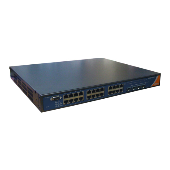
RGPS-R9244GP+-P Series User Manual etting Started 1.1 About the RGPS-R9244GP+-P The RGPS-P9244GP+-P is a Layer-3 PoE Gigabit managed Ethernet switch with 24x 10/100/1000Base-T(X) IEEE802.3at P.S.E. ports and 4x1G/10GBase-X SFP+ ports. It is able to meet the needs for high port density and high-speed, long-distance transmission. The P.S.E-enabled ports are able to provide sufficient power for power-hungry devices with up to... -
Page 8: Hardware Specifications
RGPS-R9244GP+-P Series User Manual Supports ACL, TACACS+ and 802.1x user authentication for security Supports 9.6K Bytes Jumbo Frame SFP socket support DDM function Supports multiple notifications for incidents Supports management via Web-based interfaces, Telnet, Console (CLI), and Windows utility (Open-Vision) Supports LLDP Protocol 1.3 Hardware Specifications... -
Page 9: Hardware Overview
RGPS-R9244GP+-P Series User Manual ardware Overview 2.1 Front Panel 2.1.1 Ports and Connectors The RGPS-R92244GP+-P comes with the following ports and connectors on the front panel. Port Description 24 x 10/100/1000Base-T(X) IEEE802.3at P.S.E. ports Ethernet ports 4 x 1G/10G SFP+ ports... -
Page 10: Rear Panel
RGPS-R9244GP+-P Series User Manual Green Power is supplied over Ethernet cable SFP port Port is connected Link/Act Green Blinking Transmitting data 2.2 Rear Panel On the rear panel of the switch sits two panel module slots and one terminal block. The terminal block includes two power pairs for redundant power supply. -
Page 11: Hardware Installation
RGPS-R9244GP+-P Series User Manual ardware Installation 3.1 Rack-mount Installation The switch comes with two rack-mount kits to allow you to fasten the switch to a rack in any environments. Follow the following steps to install the switch to a rack. -
Page 12: Wiring
RGPS-R9244GP+-P Series User Manual 3.2 Wiring Attention 1. Be sure to disconnect the power cord before installing and/or wiring your switches. 2. Calculate the maximum possible current in each power wire and common wire. Observe all electrical codes dictating the maximum current allowable for each wire size. -
Page 13: 1000Base-T P.s.e. Rj-45 Port
RGPS-R9244GP+-P Series User Manual Cable Type Max. Length Connector 10BASE-T Cat. 3, 4, 5 100-ohm UTP 100 m (328 ft) RJ-45 100BASE-TX Cat. 5 100-ohm UTP UTP 100 m (328 ft) RJ-45 1000BASE-T Cat. 5/Cat. 5e 100-ohm UTP UTP 100 m (328ft) -
Page 14: Console Port Wiring
RGPS-R9244GP+-P Series User Manual RD-(receive) TD-(transmit) Not used Not used Not used Not used 1000 Base-T MDI/MDI-X Pin Assignments: Pin Number MDI port MDI-X port BI_DA+ BI_DB+ BI_DA- BI_DB- BI_DB+ BI_DA+ BI_DC+ BI_DD+ BI_DC- BI_DD- BI_DB- BI_DA- BI_DD+ BI_DC+ BI_DD- BI_DC- Note: “+”... -
Page 15: Sfp
RGPS-R9244GP+-P Series User Manual 3.3.3 SFP The switch comes with fiber optical ports that can connect to other devices using SFP modules. The fiber optical ports are in multi- or single-mode with LC connectors. Please remember that the TX port of Switch A should be connected to the RX port of Switch B. - Page 16 RGPS-R9244GP+-P Series User Manual Coupling Ring If you already have two O-Ring topologies and would like to connect the rings, you can form them into a coupling ring. All you need to do is select two switches from each ring to be connected, for example, switch A and B from Ring 1 and switch C and D from Ring 2.
- Page 17 RGPS-R9244GP+-P Series User Manual O-Chain When connecting multiple O-Rings to meet your expansion demand, you can create an O-Chain topology through the following steps. 1. Select two switches from the chain (Switch A & B) that you want to connect to the O-Ring and connect them to the switches in the ring (Switch C &...
-
Page 18: Redundancy
4.1 O-Ring 4.1.1 Introduction O-Ring is ORing's proprietary redundant ring technology, with recovery time of less than 30 milliseconds (in full-duplex Gigabit operation) or 10 milliseconds (in full-duplex Fast Ethernet operation) and up to 250 nodes. The ring protocols identify one switch as the master of the network, and then automatically block packets from traveling through any of the network’s... - Page 19 RGPS-R9244GP+-P Series User Manual Label Description Check to enable O-Ring topology. Redundant Ring Only one ring master is allowed in a ring. However, if more than one switch are set to enable Ring Master, the switch with the Ring Master lowest MAC address will be the active ring master and the others will be backup masters.
-
Page 20: O-Chain
RGPS-R9244GP+-P Series User Manual 4.2 O-Chain 4.2.1 Introduction O-Chain is ORing’s revolutionary network redundancy technology which enhances network redundancy for any backbone networks, providing ease-of-use and maximum fault-recovery swiftness, flexibility, compatibility, and cost-effectiveness in a set of network redundancy topologies. The self-healing Ethernet technology designed for distributed and complex... -
Page 21: Mrp
RGPS-R9244GP+-P Series User Manual Label Description Enable Check to enable O-Chain function Ring Port The first port connecting to the ring Ring Port The second port connecting to the ring Edge Port An O-Chain topology must begin with edge ports. The ports with a smaller switch MAC address will serve as the backup link and RM LED will light up. -
Page 22: Stp/Rstp/Mstp
RGPS-R9244GP+-P Series User Manual 4.4 STP/RSTP/MSTP 4.4.1 STP/RSTP STP (Spanning Tree Protocol), and its advanced versions RSTP (Rapid Spanning Tree Protocol) and MSTP (Multiple Spanning Tree Protocol), are designed to prevent network loops and provide network redundancy. Network loops occur frequently in large networks as when two or more paths run to the same destination, broadcast packets may get in to an infinite loop and hence causing congestion in the network. - Page 23 RGPS-R9244GP+-P Series User Manual Label Description The switch port number to which the following settings will be Port applied. The current STP port role of the CIST port. The values include: CIST Role AlternatePort, BackupPort, RootPort, and DesignatedPort. The current STP port state of the CIST port. The values include: State Blocking, Learning, and Forwarding.
- Page 24 RGPS-R9244GP+-P Series User Manual The number of (legacy) topology change notification BPDUs received/transmitted on the port Discarded The number of unknown spanning tree BPDUs received (and discarded) Unknown on the port. Discarded The number of illegal spanning tree BPDUs received (and discarded) on Illegal the port.
-
Page 25: Mstp
RGPS-R9244GP+-P Series User Manual Click to undo any changes made locally and revert to previously Reset saved values. 4.4.2 MSTP Since the recovery time of STP and RSTP takes seconds, which are unacceptable in some industrial applications, MSTP was developed. The technology supports multiple spanning trees within a network by grouping and mapping multiple VLANs into different spanning-tree instances, known as MSTIs, to form individual MST regions. - Page 26 RGPS-R9244GP+-P Series User Manual Label Description The switch port number of the corresponding STP CIST (and Port MSTI) port Configures the path cost incurred by the port. Auto will set the path cost according to the physical link speed by using the 802.1D-recommended values.
- Page 27 RGPS-R9244GP+-P Series User Manual Label Description The name which identifies the VLAN to MSTI mapping. Bridges must share the name and revision (see below), as well as the Configuration Name VLAN-to-MSTI mapping configurations in order to share spanning trees for MSTIs (intra-region). The name should not exceed 32 characters.
-
Page 28: Cist
RGPS-R9244GP+-P Series User Manual Label Description The bridge instance. CIST is the default instance, which is always MSTI active. Indicates bridge priority. The lower the value, the higher the Priority priority. The bridge priority, MSTI instance number, and the 6-byte MAC address of the switch forms a bridge identifier. - Page 29 RGPS-R9244GP+-P Series User Manual active topology for the network. Lower path cost ports are chosen as forwarding ports in favor of higher path cost ports. The range of valid values is 1 to 200000000. Configures the priority for ports having identical port costs. (See Priority above).
-
Page 30: Fast Recovery
RGPS-R9244GP+-P Series User Manual 4.5 Fast Recovery Fast recovery mode can be set to connect multiple ports to one or more switches. The device’s fast recovery mode will provide redundant links. Fast recovery mode supports 28 priorities. Only the first priority will be the active port, and the other ports with different priorities will be backup ports. -
Page 31: Management
RGPS-R9244GP+-P Series User Manual anagement The switch can be controlled via a built-in web server which supports Internet Explorer (Internet Explorer 5.0 or above versions) and other Web browsers such as Chrome. Therefore, you can manage and configure the switch easily and remotely. You can also upgrade firmware via a web browser. -
Page 32: Basic Settings
RGPS-R9244GP+-P Series User Manual After logging in, you can see the information of the switch as below. On the right hand side of the management interface shows links to various settings. You can click on the links to access the configuration pages of different functions. -
Page 33: Admin Password
RGPS-R9244GP+-P Series User Manual A domain name is a text string consisting of alphabets (A-Z, a-z), digits (0-9), and minus sign (-). Space is not allowed to be part of the name. The first character must be an alpha character. And the first or last character must not be a minus sign. -
Page 34: Ip Settings
RGPS-R9244GP+-P Series User Manual via one of the management interfaces. Label Description Client The management client for which the configuration below applies. Authentication Method can be set to one of the following values: None: authentication is disabled and login is not possible. - Page 35 RGPS-R9244GP+-P Series User Manual Label Description Configure whether the IP stack should act as a host or a router. In Host mode, IP traffic between interfaces will not be routed. In Mode Router mode traffic is routed between all interfaces.
-
Page 36: Ip Status
RGPS-R9244GP+-P Series User Manual that can be used as a shorthand way of representing multiple 16-bit groups of contiguous zeros; but it can appear only once. It can also represent a legally valid IPv4 address. For example: 192.1.2.34. The field may be left blank if IPv6 operation on the interface is not desired. -
Page 37: Sntp
RGPS-R9244GP+-P Series User Manual 5.1.6 SNTP SNTP (Simple Network Time Protocol) is a protocol able to synchronize the time on your system to the clock on the Internet. It will synchronize your computer system time with a server that has already been synchronized by a source such as a radio, satellite receiver or modem. -
Page 38: Daylight Saving Time
RGPS-R9244GP+-P Series User Manual 5.1.7 Daylight Saving Time Label Description Time Zone: Set the switch location time zone. The following table lists the different location time zone for your reference. Time Zone Acronym: User can set the acronym of the time zone. This is a Configuration User configurable acronym to identify the time zone. - Page 39 RGPS-R9244GP+-P Series User Manual Time duration for single time configuration. ( Default : Disabled ) Start Time Settings: Set up the start time of the daylight saving time period. End Time Settings: Set up the ending time of the daylight saving time period.
-
Page 40: Rip
RGPS-R9244GP+-P Series User Manual USSR Zone 1 BT - Baghdad, USSR Zone +3 hours 3 pm ZP4 - USSR Zone 3 +4 hours 4 pm ZP5 - USSR Zone 4 +5 hours 5 pm ZP6 - USSR Zone 5 +6 hours... -
Page 41: Vrrp
RGPS-R9244GP+-P Series User Manual 5.1.9 VRRP A VRRP (Virtual Router Redundancy Protocol) is a computer networking protocol aimed to eliminate the single point of failure by automatically assigning available IP routers to participating hosts. Using a virtual router ID (VRID) address and virtual router IP (VRIP) address to represent itself, a virtual router consists of two or more physical routers, including one master router and one or more backup routers. -
Page 42: Https
RGPS-R9244GP+-P Series User Manual Priority: VRRP determines the role (master or backup) of each router in a VRRP group by priority. A router with a higher priority is more likely to become the master. VRRP priority is in the range of 0 to 255, and the greater the number, the higher the priority. -
Page 43: Ssh
RGPS-R9244GP+-P Series User Manual 5.1.11 SSH SSH (Secure Shell) is a cryptographic network protocol intended for secure data transmission and remote access by creating a secure channel between two networked PCs. You can configure the SSH mode in the following page. - Page 44 RGPS-R9244GP+-P Series User Manual Label Description Sets the transmit interval, which is the interval between regular Tx Interval transmissions of LLDP advertisements. The switch port number to which the following settings will be Port applied. Indicates the selected LLDP mode Rx only: the switch will not send out LLDP information, but LLDP information from its neighbors will be analyzed.
- Page 45 RGPS-R9244GP+-P Series User Manual Label Description Local Port The port that you use to transmits and receives LLDP frames. The identification number of the neighbor sending out the LLDP Chassis ID frames. Port ID The identification of the neighbor port Port Description The description of the port advertised by the neighbor.
- Page 46 RGPS-R9244GP+-P Series User Manual Global Counters Label Description Neighbor entries Shows the time when the last entry was deleted or added. were last changed at Total Neighbors Shows the number of new entries added since switch reboot Entries Added Total...
-
Page 47: Modbus Tcp
RGPS-R9244GP+-P Series User Manual known as TLVs (Type Length Value). If a TLV is malformed, it will be counted and discarded. TLVs Unrecognized The number of well-formed TLVs, but with an unknown type value Org. Discarded The number of organizationally TLVs received Each LLDP frame contains information about how long the LLDP information is valid (age-out time). -
Page 48: Update Firmware
RGPS-R9244GP+-P Series User Manual Choose the configuration file from a drive and click “Upload”. The file will be loaded to the device. 5.1.15 Update Firmware This page allows you to update the firmware of the switch. Simply choose the firmware file you want to use and click “Upload”. - Page 49 RGPS-R9244GP+-P Series User Manual Label Description Check to enable the DHCP Server function. If enabled, the switch will Enabled be the DHCP server on your local network Start IP Address The beginning of the dynamic IP address range. The lowest IP address in the range is considered the start IP address.
-
Page 50: Dynamic Client List
RGPS-R9244GP+-P Series User Manual 5.2.2 Dynamic Client List When DHCP server functions are activated, the switch will collect DHCP client information and display in the following table. You can assign the specific IP address which is in the assigned dynamic IP range to the specific port. When the device is connecting to the port and asks for... - Page 51 RGPS-R9244GP+-P Series User Manual Label Description Relay Mode Indicates the existing DHCP relay mode. The modes include: Enabled: activate DHCP relay. When DHCP relay is enabled, the agent forwards and transfers DHCP messages between the clients and the server when they are not in the same subnet domain to prevent the DHCP broadcast message from flooding for security considerations.
- Page 52 RGPS-R9244GP+-P Series User Manual a DHCP client. It only works when DHCP relay mode is enabled. Disabled: disable DHCP relay information Relay Information Indicates the policies to be enforced when receiving DHCP relay Policy information. When DHCP relay information mode is enabled, if the agent receives a DHCP message that already contains relay agent information, it will enforce the policy.
-
Page 53: Port Setting
RGPS-R9244GP+-P Series User Manual Label Description Transmit to Client The number of packets relayed from the server to the client Transmit Error The number of packets with errors when being sent to servers Receive from Client The number of packets received from the server... - Page 54 RGPS-R9244GP+-P Series User Manual Label Description The switch port number to which the following settings Port will be applied. The current link state is shown by different colors. Link Green indicates the link is up and red means the link is down.
-
Page 55: Port Trunk
RGPS-R9244GP+-P Series User Manual 5.3.2 Port Trunk A port trunk is a group of ports that have been grouped together to function as one logical path. This method provides an economical way for you to increase the bandwidth between the switch and another networking device. - Page 56 RGPS-R9244GP+-P Series User Manual Label Description Group ID Indicates the ID of each aggregation group. Normal means no aggregation. Only one group ID is valid per port. Port Members Lists each switch port for each group ID. Select a radio button to include a port in an aggregation, or clear the radio button to remove the port from the aggregation.
-
Page 57: Lacp System Status
RGPS-R9244GP+-P Series User Manual Label Description Port Indicates the ID of each aggregation group. Normal indicates there is no aggregation. Only one group ID is valid per port. LACP Enabled Lists each switch port for each group ID. Check to include a port in an aggregation, or clear the box to remove the port from the aggregation. -
Page 58: Lacp Port Status
RGPS-R9244GP+-P Series User Manual Label Description Aggr ID The aggregation ID is associated with the aggregation instance. For LLAG, the ID is shown as 'isid:aggr-id' and for GLAGs as 'aggr-id' Partner System ID System ID (MAC address) of the aggregation partner Partner Key When connecting the device to other manufactures’... -
Page 59: Lacp Port Statistics
RGPS-R9244GP+-P Series User Manual Label Description Port Switch port number LACP Yes means LACP is enabled and the port link is up. No means LACP is not enabled or the port link is down. Backup means the port cannot join in the aggregation group unless other ports are removed. -
Page 60: Loop Protection
RGPS-R9244GP+-P Series User Manual 5.3.3 Loop Protection This feature prevents loop attack. When receiving loop packets, the port will be disabled automatically, preventing the loop attack from affecting other network devices. Configuration Label Description Enable Loop Protection Activate loop protection functions (as a whole) -
Page 61: Vlan
RGPS-R9244GP+-P Series User Manual Port Switch port number Enable Activate loop protection functions (as a whole) Action Configures the action to take when a loop is detected. Valid values include Shutdown Port, Shutdown Port, and Log or Log Only. Tx Mode Controls whether the port is actively generating loop protection PDUs or only passively look for looped PDUs. -
Page 62: Port Configurations
RGPS-R9244GP+-P Series User Manual Label Description Delete Check to delete the entry. It will be deleted during the next save. VLAN ID The VLAN ID for the entry MAC Address The MAC address for the entry Checkmarks indicate which ports are members of the entry. - Page 63 RGPS-R9244GP+-P Series User Manual Label Description This field specifies the Ethertype used for custom S-ports. This is a global setting for all custom S-ports. Custom Ethertype enables you to change the Ethertype value on a port to any value to support network devices that do not...
- Page 64 RGPS-R9244GP+-P Series User Manual discarded. By default, ingress filtering is disabled (no check mark). Determines whether the port accepts all frames or only tagged/untagged frames. This parameter affects VLAN Frame Type ingress processing. If the port only accepts tagged frames, untagged frames received on the port will be discarded.
- Page 65 RGPS-R9244GP+-P Series User Manual Unaware on PVID) and is forwarded. Unaware port will be used for 802.1QinQ When the port receives tagged frames: set to 0x8100. (double tag). 1. If the tagged frame contains a TPID of The final status of the...
- Page 66 RGPS-R9244GP+-P Series User Manual ORing Industrial Networking Corp.
-
Page 67: Examples Of Vlan Settings
RGPS-R9244GP+-P Series User Manual Examples of VLAN Settings VLAN Access Mode: Switch Port 7 is VLAN Access mode = Untagged 20 Port 8 is VLAN Access mode = Untagged 10 Below are the switch settings. ORing Industrial Networking Corp. - Page 68 RGPS-R9244GP+-P Series User Manual VLAN 1Q Trunk Mode: ORing Industrial Networking Corp.
- Page 69 RGPS-R9244GP+-P Series User Manual Switch Port 1 = VLAN 1Qtrunk mode = tagged 10, 20 Port 2 = VLAN 1Qtrunk mode = tagged 10, 20 Below are the switch settings. VLAN Hybrid Mode: Port 1 VLAN Hybrid mode = untagged 10 Tagged 10, 20 ORing Industrial Networking Corp.
- Page 70 RGPS-R9244GP+-P Series User Manual Below are the switch settings. VLAN QinQ Mode: VLAN QinQ mode is usually adopted when there are unknown VLANs, as shown in the figure below ORing Industrial Networking Corp.
- Page 71 RGPS-R9244GP+-P Series User Manual VLAN “X” = Unknown VLAN 9000 Series Port 1 VLAN Settings: VLAN ID Settings When setting the management VLAN, only the same VLAN ID port can be used to control the switch. ORing Industrial Networking Corp.
-
Page 72: Private Vlan
RGPS-R9244GP+-P Series User Manual 9000 Series VLAN Settings: 5.4.3 Private VLAN A private VLAN contains switch ports that can only communicate with a given "uplink". The restricted ports are called private ports. Each private VLAN typically contains many private ports and a single uplink. The switch forwards all frames received on a private port out the uplink port, regardless of VLAN ID or destination MAC address. -
Page 73: Snmp
RGPS-R9244GP+-P Series User Manual VLAN ID. You can check the box to include a port in a private VLAN. To remove or exclude the port from the private VLAN, make sure the box is unchecked. By default, no ports are members, and all boxes are unchecked. -
Page 74: System
RGPS-R9244GP+-P Series User Manual 5.5.1 System Label Description Indicates existing SNMP mode. Possible modes include: Mode Enabled: enable SNMP mode Disabled: disable SNMP mode Indicates the supported SNMP version. Possible versions include: SNMP v1: supports SNMP version 1. Version SNMP v2c: supports SNMP version 2c. -
Page 75: Trap Configuration
RGPS-R9244GP+-P Series User Manual 5.5.2 Trap Configuration ORing Industrial Networking Corp. - Page 76 RGPS-R9244GP+-P Series User Manual Label Description Indicates existing SNMP trap mode. Possible modes include: Trap Mode Enabled: enable SNMP trap mode Disabled: disable SNMP trap mode Indicates the supported SNMP trap version. Possible versions include: Trap Version SNMP v1: supports SNMP trap version 1...
-
Page 77: Snmp Community Configurations
RGPS-R9244GP+-P Series User Manual ID for these traps and informs is needed. When "Trap Probe Security Engine ID" is enabled, the ID will be probed automatically. Otherwise, the ID specified in this field is used. The string must contain an even number (in hexadecimal format) with number of digits between 10 and 64, but all-zeros and all-'F's are not allowed. - Page 78 RGPS-R9244GP+-P Series User Manual table. The entry index keys are Engine ID and User Name. Label Description Delete Check to delete the entry. It will be deleted during the next save. An octet string identifying the engine ID that this entry should belong to.
-
Page 79: Snmp Group Configurations
RGPS-R9244GP+-P Series User Manual authentication protocol The value of security level cannot be modified if the entry already exists, which means the value must be set correctly at the time of entry creation. A string identifying the authentication pass phrase. For MD5 Authentication authentication protocol, the allowed string length is 8 to 32. -
Page 80: Snmp View Configurations
RGPS-R9244GP+-P Series User Manual security models included: v1: Reserved for SNMPv1. v2c: Reserved for SNMPv2c. usm: User-based Security Model (USM). A string identifying the security name that this entry should belong to. Security Name The allowed string length is 1 to 32, and only ASCII characters from 33 to 126 are allowed. -
Page 81: Snmp Access Configurations
RGPS-R9244GP+-P Series User Manual The OID defining the root of the subtree to add to the named view. OID Subtree The allowed OID length is 1 to 128. The allowed string content is digital number or asterisk (*). 5.5.7 SNMP Access Configurations This page allows you to configure SNMPv3 access table. -
Page 82: Traffic Prioritization
RGPS-R9244GP+-P Series User Manual 5.6 Traffic Prioritization 5.6.1 Storm Control A LAN storm occurs when packets flood the LAN, creating excessive traffic and degrading network performance. Errors in the protocol-stack implementation, mistakes in network configuration, or users issuing a denial-of-service attack can cause a storm. Storm control prevents traffic on a LAN from being disrupted by a broadcast, multicast, or unicast storm on a port. - Page 83 RGPS-R9244GP+-P Series User Manual Label Description Port The port number for which the configuration below applies Controls the default QoS class All frames are classified to a QoS class. There is a one to one mapping between QoS class, queue, and priority. A QoS class of 0 (zero) has the lowest priority.
-
Page 84: Port Tag Remaking
RGPS-R9244GP+-P Series User Manual value in the tag. Otherwise the frame is classified to the default DP level. If the port is VLAN aware, the frame is tagged, and Tag Class is enabled, then the frame is classified to a DP level that is mapped from the PCP and DEI value in the tag. -
Page 85: Port Dscp
RGPS-R9244GP+-P Series User Manual Label Description The switch port number to which the following settings will be Port applied. Click on the port number to configure tag remarking Shows the tag remarking mode for this port Classified: use classified PCP/DEI values... -
Page 86: Port Policing
RGPS-R9244GP+-P Series User Manual Label Description Shows the list of ports for which you can configure DSCP Ingress Port and Egress settings. In Ingress settings you can change ingress translation and classification settings for individual ports. There are two configuration parameters available in Ingress:... -
Page 87: Queue Policing
RGPS-R9244GP+-P Series User Manual Label Description Port The port number for which the configuration below applies Enabled Check to enable the policer for individual switch ports Configures the rate of each policer. The default value is 500. This Rate value is restricted to 100 to 1000000 when the Unit is kbps or fps, and is restricted to 1 to 3300 when the Unit is Mbps or kfps. -
Page 88: Port Scheduler
RGPS-R9244GP+-P Series User Manual when the Unit is kbps, and is restricted to 1 to 3300 when the Unit is Mbps. This field is only shown if at least one of the queue policers is enabled. Configures the unit of measurement for each queue policer rate as kbps or Mbps. - Page 89 RGPS-R9244GP+-P Series User Manual Label Description Two scheduling modes are available: Strict Priority or Scheduler Mode Weighted Queue Shaper Enable Check to enable queue shaper for individual switch ports Configures the rate of each queue shaper. The default value is 500. This value is restricted to 100 to 1000000 whn Queue Shaper Rate the Unit is kbps", and it is restricted to 1 to 3300 when the...
- Page 90 RGPS-R9244GP+-P Series User Manual Configures the rate of each port shaper. The default value is 500 This value is restricted to 100 to 1000000 when the Port Shaper Rate Unit is kbps, and it is restricted to 1 to 3300 when the Unit is Mbps.
-
Page 91: Port Shaping
RGPS-R9244GP+-P Series User Manual Label Description Two scheduling modes are available: Strict Priority or Scheduler Mode Weighted Check to enable queue shaper for individual switch Queue Shaper Enable ports Configures the rate of each queue shaper. The default value is 500. This value is restricted to 100 to 1000000... -
Page 92: Dscp-Based Qos
RGPS-R9244GP+-P Series User Manual Label Description The switch port number to which the following settings will be Port applied. Click on the port number to configure the shapers Mode Shows disabled or actual queue shaper rate - e.g. "800 Mbps"... -
Page 93: Dscp Translation
RGPS-R9244GP+-P Series User Manual 5.6.10 DSCP Translation This page allows you to configure basic QoS DSCP translation settings for all switches. DSCP translation can apply to Ingress or Egress. Label Description Maximum number of supported DSCP values is 64 and valid DSCP DSCP value ranges from 0 to 63. -
Page 94: Dscp Classification
RGPS-R9244GP+-P Series User Manual Remap DP1: Re-maps DP1 field to selected DSCP value. DP1 indicates a drop precedence with a high priority. You can select the DSCP value from a selected menu to which you want to remap. DSCP value ranges from 0 to 63. - Page 95 RGPS-R9244GP+-P Series User Manual Label Description Port Members Check to include the port in the QCL entry. By default, all ports are included. Key Parameters Key configurations include: Tag: value of tag, can be Any, Untag or Tag. VID: valid value of VLAN ID from 1 to 4095 Any: can be a specific value or a range of VIDs.
- Page 96 RGPS-R9244GP+-P Series User Manual SSAP Address: valid SSAP (Source Service Access Point) values can range from 0x00 to 0xFF or Any. The default value is Any. DSAP Address: valid DSAP (Destination Service Access Point) values can range from 0x00 to 0xFF or Any. The default value is Any.
-
Page 97: Qos Counters
RGPS-R9244GP+-P Series User Manual AF11-AF43) or Default. Default means that the default classified value is not modified by this QCE. 5.6.13 QoS Counters This page shows information on the number of packets sent and received at each queue. Label Description... - Page 98 RGPS-R9244GP+-P Series User Manual Label Description User Indicates the QCL user QCE# Indicates the index of QCE Indicates the type of frame to look for incoming frames. Possible frame types are: Any: the QCE will match all frame type. Ethernet: Only Ethernet frames (with Ether Type 0x600-0xFFFF) Frame Type are allowed.
-
Page 99: Multicast
RGPS-R9244GP+-P Series User Manual 5.7 Multicast 5.7.1 IGMP Snooping Basic Configuration IGMP (Internet Group Management Protocol) snooping monitors the IGMP traffic between hosts and multicast routers. The switch uses what IGMP snooping learns to forward multicast traffic only to interfaces that are connected to interested receivers. This conserves bandwidth by allowing the switch to send multicast traffic to only those interfaces that are connected to hosts that want to receive the traffic, instead of flooding the traffic to all interfaces in the VLAN. -
Page 100: Vlan Configurations
RGPS-R9244GP+-P Series User Manual VLAN Configurations If a VLAN is not IGMP snooping-enabled, it floods multicast data and control packets to the entire VLAN in hardware. When snooping is enabled, IGMP packets are trapped to the CPU. Data packets are mirrored to the CPU in addition to being VLAN flooded. The CPU then installs hardware resources, so that subsequent data packets can be switched to desired ports in hardware without going to the CPU. - Page 101 RGPS-R9244GP+-P Series User Manual Status This page provides IGMP snooping status. Label Description VLAN ID The VLAN ID of the entry Querier Version Active Querier version Host Version Active Host version Querier Status Shows the Querier status as ACTIVE or IDLE...
-
Page 102: Security
RGPS-R9244GP+-P Series User Manual Label Description VLAN ID The VLAN ID of the group Groups The group address of the group displayed Port Members Ports under this group Security 5.8.1 Remote Control Security Remote Control Security allows you to limit remote access to the management interface. -
Page 103: Device Binding
RGPS-R9244GP+-P Series User Manual 5.8.2 Device Binding Device binding is ORing’s proprietary technology which binds the IP/MAC address of a device with a specified Ethernet port. If the IP/MAC address of the device connected to the Ethernet port does not conform to the binding requirements, the device will be locked for security concerns. -
Page 104: Advanced Configurations
RGPS-R9244GP+-P Series User Manual Low: the stream is getting low. DdoS Prevention Check to enable DDOS prevention. When enabled, the switch will Acton monitor the device against DDOS attacks. Indicates DDOS prevention status. Possible statuses are: ---: disable DdoS Prevention... - Page 105 RGPS-R9244GP+-P Series User Manual Label Description Link Change Disables or enables the port Only log it Simply sends logs to the log server Shunt Down the Disables the port Port Reboot Device Disables or enables PoE power DdoS Prevention The switch can monitor ingress packets, and perform actions when DDOS attack occurred on this port.
- Page 106 RGPS-R9244GP+-P Series User Manual Label Description Mode Enables or disables DDOS prevention of the port Indicates the level of DDOS detection. Possible levels are: Low: low sensibility Sensibility Normal: normal sensibility Medium: medium sensibility High: high sensibility Indicates the types of DdoS attack packets to be monitored. Possible...
- Page 107 RGPS-R9244GP+-P Series User Manual Device Description This page allows you to configure device description settings. Label Description Indicates device types. Possible types are: ---: no specification IP Camera IP Phone Device Type Access Point Network Video Recorder Indicates location information of the device. The information can be Location Address used for Google Mapping.
-
Page 108: Acl
RGPS-R9244GP+-P Series User Manual Label Description Mode Enables or disables stream monitoring of the port Indicates the action to take when the stream gets low. Possible actions are: Action ---: no action Log it: simply logs the event 5.8.3 ACL An ACL (Access Control List) is a list of permissions attached to an object. - Page 109 RGPS-R9244GP+-P Series User Manual Label Description Port The switch port number to which the following settings will be applied Select to apply a policy to the port. The allowed values are 1 to 8. Policy ID The default value is 1.
- Page 110 RGPS-R9244GP+-P Series User Manual Label Description Rate Limiter ID The rate limiter ID for the settings contained in the same row. The rate unit is packet per second (pps), which can be configured as 1, 2, 4, 8, 16, 32, 64, 128, 256, 512, 1K, 2K, 4K, 8K, 16K, 32K, 64K, Rate 128K, 256K, 512K, or 1024K.
- Page 111 RGPS-R9244GP+-P Series User Manual choose this value. Two fields for entering a policy value and bitmask appear. Policy Value: When "Specific" is selected for the policy filter, you can enter a specific policy value. The allowed range is 0 to 255 Policy Bitmask: When "Specific"...
- Page 112 RGPS-R9244GP+-P Series User Manual Label Description Specify the Ethernet type filter for this ACE, including: Any: No EtherType filter is specified (EtherType filter status is "don't-care"). EtherType Filter Specific: If you want to filter a specific EtherType filter with this ACE, you can enter a specific EtherType value.
- Page 113 RGPS-R9244GP+-P Series User Manual Specifies the available ARP/RARP opcode (OP) flag for the ACE Any: no ARP/RARP OP flag is specified (OP is "don't-care"). Request/Reply Request: frame must have ARP Request or RARP Request OP flag set. Reply: frame must have ARP Reply or RARP Reply OP flag.
- Page 114 RGPS-R9244GP+-P Series User Manual Specifies whether frames will meet the action according to their ARP/RARP hardware address length (HLN) and protocol address length (PLN) settings. IP/Ethernet 0: ARP/RARP frames where the HLN is equal to Ethernet (0x06) and Length the (PLN) is equal to IPv4 (0x04) must not match this entry.
- Page 115 RGPS-R9244GP+-P Series User Manual Label Description Specifies the IP protocol filter for the ACE Any: no IP protocol filter is specified ("don't-care"). Specific: if you want to filter a specific IP protocol filter with the ACE, choose this value. A field for entering an IP protocol filter appears.
- Page 116 RGPS-R9244GP+-P Series User Manual the SIP Address field that appears. Network: source IP filter is set to Network. Specify the source IP address and source IP mask in the SIP Address and SIP Mask fields that appear. Specifies the destination IP filter for the ACE Any: no destination IP filter is specified (destination IP filter is "don't-care").
- Page 117 RGPS-R9244GP+-P Series User Manual Specific: If you want to filter a specific destination MAC address with the ACE, choose this value. A field for entering a DMAC value appears. When Specific is selected for the DMAC filter, you can enter a specific DMAC Value destination MAC address.
- Page 118 RGPS-R9244GP+-P Series User Manual Label Description Specifies the ICMP filter for the ACE Any: no ICMP filter is specified (ICMP filter status is "don't-care"). ICMP Type Filter Specific: if you want to filter a specific ICMP filter with the ACE, you can enter a specific ICMP value.
- Page 119 RGPS-R9244GP+-P Series User Manual entering a TCP/UDP source value appears. Range: if you want to filter a specific TCP/UDP source range filter with the ACE, you can enter a specific TCP/UDP source range. A field for entering a TCP/UDP source value appears.
-
Page 120: Aaa (Authentication, Authorization, And Accounting)
RGPS-R9244GP+-P Series User Manual the ACE 0: TCP frames where the SYN field is set must not be able to match this entry. 1: TCP frames where the SYN field is set must be able to match this entry. Any: any value is allowed ("don't-care"). - Page 121 RGPS-R9244GP+-P Series User Manual devices or applications communicate with an AAA server is RADIUS (Remote Authentication Dial-In User Service). RADIUS is a protocol used between the switch and the authentication server. This page allows you to configure common settings for an authentication server.
- Page 122 RGPS-R9244GP+-P Series User Manual Indicates the identifying IP Address of the NAS which is requesting NAS-IP-Address authentication of the user, and SHOULD be unique to the NAS within the scope of the RADIUS server. Network Access Server identifier (NAS-ID) for the interface. The...
-
Page 123: Radius Overview
RGPS-R9244GP+-P Series User Manual The shared secret between the switch and the RADIUS server. The time to wait for the RADIUS server to respond. Timeout The number of times the switch tries to connect to a RADIUS Retransmit server. RADIUS Overview This page provides information about the status of the RADIUS server configurable on the authentication configuration page. -
Page 124: Radius Details
RGPS-R9244GP+-P Series User Manual Label Description The RADIUS server number. Click to navigate to detailed statistics of the server The IP address and UDP port number (in <IP Address>:<UDP Port> IP Address notation) of the server The current status of the server. This field has one of the following values: Disabled: the server is disabled. - Page 125 RGPS-R9244GP+-P Series User Manual Label Description RADIUS authentication server packet counters. There are seven ‘receive’ and four ‘transmit’ counters. Packet Counters This section contains information about the state of the server and the latest round-trip time. Other Info ORing Industrial Networking Corp.
-
Page 126: Nas (802.1X)
RGPS-R9244GP+-P Series User Manual Label Description RADIUS accounting server packet counters. There are five ‘receive’ four ‘transmit’ counters. Packet Counters This section contains information about the state of the server and the latest round-trip time. Other Info 5.8.5 NAS (802.1x) A NAS (Network Access Server) is an access gateway between an external communications network and an internal network. - Page 127 RGPS-R9244GP+-P Series User Manual Overview of 802.1X (Port-Based) Authentication In an 802.1X network environment, the user is called the supplicant, the switch is the authenticator, and the RADIUS server is the authentication server. The switch acts as the man-in-the-middle, forwarding requests and responses between the supplicant and the authentication server.
-
Page 128: Configuration
RGPS-R9244GP+-P Series User Manual When authentication is complete, the RADIUS server sends a success or failure indication, which in turn causes the switch to open up or block traffic for that particular client, using static entries into the MAC Table. Only then will frames from the client be forwarded on the switch. - Page 129 RGPS-R9244GP+-P Series User Manual If checked, clients are reauthenticated after the interval specified Reauthentication Period. Reauthentication 802.1X-enabled ports can be used to detect if a new device is plugged into a switch port. Reauthentication For MAC-based ports, reauthentication is only useful if the Enabled RADIUS server configuration has changed.
- Page 130 RGPS-R9244GP+-P Series User Manual hold in Unauthorized state. The hold timer does not count during an on-going authentication. The switch will ignore new frames coming from the client during the hold time. The hold time can be set to a number between 10 and 1000000 seconds.
- Page 131 RGPS-R9244GP+-P Series User Manual When authentication is complete, the RADIUS server sends a special packet containing a success or failure indication. Besides forwarding the result to the supplicant, the switch uses it to open up or block traffic on the switch port connected to the supplicant.
- Page 132 RGPS-R9244GP+-P Series User Manual MAC address once successfully authenticated. b. Multi 802.1X In port-based 802.1X authentication, once a supplicant is successfully authenticated on a port, the whole port is opened for network traffic. This allows other clients connected to the port (for...
- Page 133 RGPS-R9244GP+-P Series User Manual string in the following form "xx-xx-xx-xx-xx-xx", that is, a dash (-) is used as separator between the lower-cased hexadecimal digits. The switch only supports the MD5-Challenge authentication method, so the RADIUS server must be configured accordingly.
- Page 134 RGPS-R9244GP+-P Series User Manual enabled when authentication is globally enabled and the port's Admin State is in an EAPOL-based or MAC-based mode. Clicking these buttons will not cause settings changed on the page to take effect. Reauthenticate: schedules a reauthentication whenever the quiet-period of the port runs out (EAPOL-based authentication).
- Page 135 RGPS-R9244GP+-P Series User Manual The user name (supplicant identity) carried in the most recently received Response Identity EAPOL frame for EAPOL-based Last ID authentication, and the source MAC address from the most recently received frame from a new client for MAC-based authentication.
- Page 136 RGPS-R9244GP+-P Series User Manual These backend (RADIUS) frame counters are available for the following administrative states: • 802.1X • MAC-based Auth. Backend Server Counters Information about the last supplicant/client that attempts Last authenticate. This information available for following Supplicant/Client administrative states: Info •...
-
Page 137: Warning
RGPS-R9244GP+-P Series User Manual 5.9 Warning 5.9.1 Fault Alarm When any selected fault event happens, the Fault LED on the switch panel will light up and the electric relay will signal at the same time. The following pages allow you to set up alert conditions based on your needs for individual switch ports, including actions to be taken during disconnection and power failure. -
Page 138: Smtp Setting
RGPS-R9244GP+-P Series User Manual packet is lost due to network disconnection and no UDP packet will be resent. Label Description Server Mode Indicates existing server mode. When the mode operation is enabled, the syslog message will be sent to syslog server. - Page 139 RGPS-R9244GP+-P Series User Manual Label Description E-mail Alarm Enables or disables transmission of system warnings by e-mail Sender E-mail SMTP server IP address Address Mail Subject Subject of the mail Authentication Username: the authentication username Password: the authentication password Confirm Password: re-enter password...
- Page 140 RGPS-R9244GP+-P Series User Manual Label Description System Cold Start Sends out alerts when the system is restarted Power Status Sends out alerts when power is up or down SNMP Authentication Sends out alert when SNMP authentication fails Failure Redundant Ring...
-
Page 141: Monitor And Diag
RGPS-R9244GP+-P Series User Manual 5.10 Monitor and Diag 5.10.1 MAC Table A MAC address tablet is a table in a network switch that maps MAC addresses to ports. The switch uses the table to determine which port the incoming packet should be forwarded to. - Page 142 RGPS-R9244GP+-P Series User Manual MAC Table Learning The switch can add the address and port on which the packet was received to the MAC table if the address does not exist in the table by examining the source address of each packet received on a port.
- Page 143 RGPS-R9244GP+-P Series User Manual Label Description Delete Check to delete an entry. It will be deleted during the next save. VLAN ID The VLAN ID for the entry MAC Address The MAC address for the entry Checkmarks indicate which ports are members of the entry.
-
Page 144: Port Statistics
RGPS-R9244GP+-P Series User Manual Label Description Type Indicates whether the entry is a static or dynamic entry MAC address The MAC address of the entry VLAN The VLAN ID of the entry Port Members The ports that are members of the entry. -
Page 145: Detailed Statistics
RGPS-R9244GP+-P Series User Manual Bytes The number of received and transmitted bytes per port The number of frames received in error and the number of Errors incomplete transmissions per port Drops The number of frames discarded due to ingress or egress congestion... -
Page 146: Port Mirroring
RGPS-R9244GP+-P Series User Manual Label Description Rx and Tx Packets The number of received and transmitted (good and bad) packets The number of received and transmitted (good and bad) bytes, Rx and Tx Octets including FCS, except framing bits The number of received and transmitted (good and bad) unicast... -
Page 147: System Log Information
RGPS-R9244GP+-P Series User Manual Label Description The switch port number to which the following settings will be Port applied. Drop-down list for selecting a mirror mode. Rx only: only frames received on this port are mirrored to the mirror port. Frames transmitted are not mirrored. -
Page 148: Veriphycable Diagnostics
RGPS-R9244GP+-P Series User Manual Label Description Check this box to enable an automatic refresh of the page at Auto-refresh regular intervals. Refresh Updates system log entries, starting from the current entry ID Clear Flushes all system log entries Updates system log entries, starting from the first available |<<... -
Page 149: Sfp Monitor
RGPS-R9244GP+-P Series User Manual all ports are selected, this can take approximately 15 seconds. When completed, the page refreshes automatically, and you can view the cable diagnostics results in the cable status table. Note that VeriPHY diagnostics is only accurate for cables 7 - 140 meters long. 10 and 100 Mbps ports will be disconnected while running VeriPHY diagnostics. -
Page 150: Ping
RGPS-R9244GP+-P Series User Manual 5.10.7 Ping This command sends ICMP echo request packets to another node on the network. Using the ping command, you can see if another site on the network can be reached Label Description IP Address The destination IP Address Ping Length The payload size of the ICMP packet. -
Page 151: Ipv6 Ping
RGPS-R9244GP+-P Series User Manual value. Ping Interval Specifies the interval between pings that are sent to the destination address. After you press Start, five ICMP packets will be transmitted, and the sequence number and round trip time will be displayed upon reception of a reply. The page refreshes automatically until responses to all packets are received, or until a timeout occurs PING6 server ::10.10.132.20... -
Page 152: Sfp Type
RGPS-R9244GP+-P Series User Manual Ping Interval Specifies the interval between pings that are sent to the destination address. Egress Interface Specifies a physical interface over which you can verify connectivity. If you specify a physical interface, such as an Ethernet interface, you must also specify the port number of the interface. -
Page 153: Synchronization
RGPS-R9244GP+-P Series User Manual 5.11 Synchronization 5.11.1 PTP PTP External Clock Mode is a protocol for synchronizing clocks throughout a computer network. On a local area network, it achieves clock accuracy in the sub-microsecond range, making it suitable for measurement and control systems. - Page 154 RGPS-R9244GP+-P Series User Manual Label Description Delete Check this box and click Save to delete the clock instance Clock Instance Indicates the instance of a particular clock instance [0..3] Click on the clock instance number to edit the clock details Device Type Indicates the type of the clock instance.
-
Page 155: Poe
RGPS-R9244GP+-P Series User Manual For more information, please refer to Unicast Slave Configuration VLAN Tag Enable Enables VLAN tagging for PTP frames Note: Packets are only tagged if the port is configured for vlan tagging. i.e: Port Type != Unaware and PortVLAN mode == None, and the port is member of the VLAN. - Page 156 RGPS-R9244GP+-P Series User Manual Label Description Reserved Power There are three modes available when configuring the reserved determined by power of each port or power devices. Allocation: users can allocate the amount of power that each port reserves. The allocated/reserved power for each port/power device is specified in the Maximum Power field.
- Page 157 RGPS-R9244GP+-P Series User Manual than the reserved power for the port, the port is shut down. Power Management There are two modes available when configuring when to shut Mode down the port: Actual Consumption: the ports are shut down when the actual...
-
Page 158: Status
RGPS-R9244GP+-P Series User Manual 5.12.2 Status This page allows you to examine the current status for all PoE ports. Label Description Local Port The switch port number to which the following settings will be applied. PD Class Each power device is classified according to the class that defines the maximum power consumed by the PD. -
Page 159: Poe Schedule
RGPS-R9244GP+-P Series User Manual the power supply can deliver, and port(s) with the lowest priority will be powered down. No PD detected: no power devices detected on the port PoE turned OFF: power devices overload. The power devices have requested or used more power than the port can deliver, and the port is powered down. -
Page 160: Factory Defaults
RGPS-R9244GP+-P Series User Manual Label Description Enables or disables ping check function Ping Check Send Mail When ping fails, an email notification will be sent Port Ports which you want to perform auto-ping check function Ping IP Address Enter an IP address... -
Page 161: System Reboot
RGPS-R9244GP+-P Series User Manual Label Description Click to reset the configuration to factory defaults Click to return to the Port State page without resetting 5.14 System Reboot You can reset the stack switch on this page. After reset, the system will boot normally as if you... -
Page 162: Command Line Interface Management
RGPS-R9244GP+-P Series User Manual ommand Line Interface Management Besides Web-based management, the device also supports CLI management. You can use console or telnet to manage the switch by CLI. CLI Management by RS-232 Serial Console (115200, 8, none, 1, none) Before configuring RS-232 serial console, connect the RS-232 port of the switch to your PC Com port using a RJ45 to DB9-F cable. - Page 163 RGPS-R9244GP+-P Series User Manual Step 2: Input a name for the new connection. Step 3: Select a COM port in the drop-down list. Step 4: A pop-up window that indicates COM port properties appears, including bits per ORing Industrial Networking Corp.
- Page 164 RGPS-R9244GP+-P Series User Manual second, data bits, parity, stop bits, and flow control. Step 5: The console login screen will appear. Use the keyboard to enter the Username and Password (same as the password for Web browsers), then press Enter.
- Page 165 RGPS-R9244GP+-P Series User Manual IP Address: 192.168.10.1 Subnet Mask: 255.255.255.0 Default Gateway: 192.168.10.254 User Name: admin Password: admin Follow the steps below to access console via Telnet. Step 1: Telnet to the IP address of the switch from the Run window by inputting commands (or from the MS-DOS prompt) as below.
- Page 166 RGPS-R9244GP+-P Series User Manual Commander Groups ORing Industrial Networking Corp.
- Page 167 RGPS-R9244GP+-P Series User Manual System Configuration [all] [<port_list>] Reboot Restore Default [keep_ip] Contact [<contact>] Name [<name>] Location [<location>] System> Description [<description>] Password <password> Username [<username>] Timezone [<offset>] Log [<log_id>] [all|info|warning|error] [clear] Configuration DHCP [enable|disable] IP> Setup [<ip_addr>] [<ip_mask>] [<ip_router>] [<vid>] Ping <ip_addr_string>...
- Page 168 RGPS-R9244GP+-P Series User Manual Lookup <mac_addr> [<vid>] Agetime [<age_time>] Learning [<port_list>] [auto|disable|secure] Dump [<mac_max>] [<mac_addr>] [<vid>] Statistics [<port_list>] Flush VLAN Configuration [<port_list>] PVID [<port_list>] [<vid>|none] FrameType [<port_list>] [all|tagged|untagged] IngressFilter [<port_list>] [enable|disable] tx_tag [<port_list>] [untag_pvid|untag_all|tag_all] PortType [<port_list>] [unaware|c-port|s-port|s-custom-port] EtypeCustomSport [<etype>] Add <vid>|<name> [<ports_list>] VLAN>...
- Page 169 RGPS-R9244GP+-P Series User Manual Authentication, Authorization and Accounting setting Security Switch Password <password> Auth Authentication Secure Shell Security/switch> HTTPS Hypertext Transfer Protocol over Secure Socket Layer RMON Remote Network Monitoring Security Switch Authentication Configuration Security/switch/auth> Method [console|telnet|ssh|web] [none|local|radius] [enable|disable] Security Switch SSH Configuration Security/switch/ssh>...
- Page 170 RGPS-R9244GP+-P Series User Manual Security Network Psec Port Security Status Network Access Server (IEEE 802.1X) Security/Network> Access Control List DHCP Dynamic Host Configuration Protocol Security Network Psec Switch [<port_list>] Security/Network/Psec> Port [<port_list>] Security Network NAS Configuration [<port_list>] Mode [enable|disable] State [<port_list>] [auto|authorized|unauthorized|macbased] Reauthentication [enable|disable] ReauthPeriod [<reauth_period>]...
- Page 171 RGPS-R9244GP+-P Series User Manual (icmp [<sip>] [<dip>] [<icmp_type>] [<icmp_code>] [<ip_flags>]) | (udp [<sip>] [<dip>] [<sport>] [<dport>] [<ip_flags>]) | (tcp [<sip>] [<dip>] [<sport>] [<dport>] [<ip_flags>] [<tcp_flags>])] [permit|deny] [<rate_limiter>] [<port_redirect>] [<mirror>] [<logging>][<shutdown>] Delete <ace_id> Lookup [<ace_id>] Clear Status [combined|static|loop_protect|dhcp|ptp|ipmc|conflicts] Port State [<port_list>] [enable|disable]...
- Page 172 RGPS-R9244GP+-P Series User Manual Txhold [<holdcount>]lt 15:15:15, Dec 6 2007 MaxAge [<max_age>] FwdDelay [<delay>] bpduFilter [enable|disable] bpduGuard [enable|disable] recovery [<timeout>] CName [<config-name>] [<integer>] Status [<msti>] [<port_list>] Msti Priority [<msti>] [<priority>] Msti Map [<msti>] [clear] Msti Add <msti> <vid> Port Configuration [<port_list>] Port Mode [<port_list>] [enable|disable]...
- Page 173 RGPS-R9244GP+-P Series User Manual Key [<port_list>] [<key>] Role [<port_list>] [active|passive] Status [<port_list>] Statistics [<port_list>] [clear] LLDP Configuration [<port_list>] Mode [<port_list>] [enable|disable] LLDP> Statistics [<port_list>] [clear] Info [<port_list>] Configuration [<port_list>] Mode [<port_list>] [disabled|poe|poe+] Priority [<port_list>] [low|high|critical] Mgmt_mode [class_con|class_res|al_con|al_res|lldp_res|lldp_con] Maximum_Power [<port_list>] [<port_power>] Status Primary_Supply [<supply_power>]...
- Page 174 RGPS-R9244GP+-P Series User Manual DSCP Classification Mode [<dscp_list>] [enable|disable] DSCP Classification Map [<class_list>] [<dpl_list>] [<dscp>] DSCP EgressRemap [<dscp_list>] [<dpl_list>] [<dscp>] Storm Unicast [enable|disable] [<packet_rate>] Storm Multicast [enable|disable] [<packet_rate>] Storm Broadcast [enable|disable] [<packet_rate>] QCL Add [<qce_id>] [<qce_id_next>] [<port_list>] [<tag>] [<vid>] [<pcp>] [<dei>] [<smac>] [<dmac_type>] [(etype [<etype>]) |...
- Page 175 RGPS-R9244GP+-P Series User Manual Holdtime [<hold_time>] IGMP Configuration [<port_list>] Mode [enable|disable] State [<vid>] [enable|disable] Querier [<vid>] [enable|disable] IGMP> Fastleave [<port_list>] [enable|disable] Router [<port_list>] [enable|disable] Flooding [enable|disable] Groups [<vid>] Status [<vid>] Configuration [<port_list>] Action [<port_list>] [permit|deny] [<rate_limiter>] [<port_copy>] [<logging>] [<shutdown>] Policy [<port_list>] [<policy>] Rate [<rate_limiter_list>] [<packet_rate>]...
- Page 176 RGPS-R9244GP+-P Series User Manual Configuration [<port_list>] Mirror> Port [<port>|disable] Mode [<port_list>] [enable|disable|rx|tx] Config Save <ip_server> <file_name> Config> Load <ip_server> <file_name> [check] Firmware Firmware Load <ip_addr_string> <file_name> > SNMP Trap Inform Retry Times [<retries>] Trap Probe Security Engine ID [enable|disable] Trap Security Engine ID [<engineid>] Trap Security Name [<security_name>]...
- Page 177 RGPS-R9244GP+-P Series User Manual Access Add <group_name> <security_model> <security_level> [<read_view_name>] [<write_view_name>] Access Delete <index> Access Lookup [<index>] Firmware Firmware Load <ip_addr_string> <file_name> > Configuration [<clockinst>] PortState <clockinst> [<port_list>] [enable|disable|internal] ClockCreate <clockinst> [<devtype>] [<twostep>] [<protocol>] [<oneway>] [<clockid>] [<tag_enable>] [<vid>] [<prio>] ClockDelete <clockinst> [<devtype>] DefaultDS <clockinst>...
- Page 178 RGPS-R9244GP+-P Series User Manual Wireless pre notification <clockinst> <port_list> Wireless delay <clockinst> [<port_list>] [<base_delay>] [<incr_delay>] Loop Protect Configuration Mode [enable|disable] Transmit [<transmit-time>] Shutdown [<shutdown-time>] Loop Protect> Port Configuration [<port_list>] Port Mode [<port_list>] [enable|disable] Port Action [<port_list>] [shutdown|shut_log|log] Port Transmit [<port_list>] [enable|disable] Status [<port_list>]...
- Page 179 RGPS-R9244GP+-P Series User Manual Syslog SnmpAuthenticationFailure [enable|disable] Syslog RingTopologyChange [enable|disable] Syslog Port [<port_list>] [disable|linkup|linkdown|both] SMTP SystemStart [enable|disable] SMTP PowerStatus [enable|disable] SMTP SnmpAuthenticationFailure [enable|disable] SMTP RingTopologyChange [enable|disable] SMTP Port [<port_list>] [disable|linkup|linkdown|both] DHCPServer Mode [enable|disable] DHCPServer> Setup [<ip_start>] [<ip_end>] [<ip_mask>] [<ip_router>] [<ip_dns>] [<ip_tftp>] [<lease>] [<bootfile>]...
- Page 180 RGPS-R9244GP+-P Series User Manual Configuration FastReocvery Mode [enable|disable] FastRecovery> Port [<port_list>] [<fr_priority>] syslog [enable|disable] SFP> temp [<temperature>] Info DeviceBinding Mode [enable|disable] Port Mode [<port_list>] [disable|scan|binding|shutdown] Port DDOS Mode [<port_list>] [enable|disable] Port DDOS Sensibility [<port_list>] [low|normal|medium|high] Port DDOS Packet [<port_list>] [rx_total|rx_unicast|rx_multicast|rx_broadcast|tcp|udp] Port DDOS Low [<port_list>] [<socket_number>]...
- Page 181 RGPS-R9244GP+-P Series User Manual Port Description [<port_list>] [<device_description>] Configuration Mode [enable|disable] Manager [enable|disable] React [enable|disable] 1stRingPort [<mrp_port>] 2ndRingPort [<mrp_port>] Parameter MRP_TOPchgT [<value>] MRP> Parameter MRP_TOPNRmax [<value>] Parameter MRP_TSTshortT [<value>] Parameter MRP_TSTdefaultT [<value>] Parameter MRP_TSTNRmax [<value>] Parameter MRP_LNKdownT [<value>] Parameter MRP_LNKupT [<value>] Parameter MRP_LNKNRmax [<value>]...
-
Page 182: T Echnical Specifications
RGPS-R9244GP+-P Series User Manual echnical Specifications ORing Switch Model RGPS-R9244GP+-P Physical Ports 10/100/1000Base-T(X) with P.S.E. Ports in RJ45 Auto MDI/MDIX 1G/10GBase-X with SFP+ port Technology IEEE 802.3 for 10Base-T IEEE 802.3u for 100Base-TX and 100Base-FX IEEE 802.3ab for 1000Base-T IEEE 802.z for 1000Base-X IEEE 802.3ae for 10Gigabit Ethernet... - Page 183 RGPS-R9244GP+-P Series User Manual Port configuration, status, statistics, monitoring, security DHCP Server/Client DHCP Relay Modbus TCP DNS client proxy SMTP Client O-Ring Open-Ring Network Redundancy O-Chain MSTP (RSTP/STP compatible) RS-232 Serial Console Port RS-232 in DB-9 connector with console cable. 115200bps, 8, N, 1...
- Page 184 RGPS-R9244GP+-P Series User Manual ORing Industrial Networking Corp.
Need help?
Do you have a question about the RGPS-R9244GP+-P Series and is the answer not in the manual?
Questions and answers