Sign In
Upload
Download
Table of Contents
Contents
Add to my manuals
Delete from my manuals
Share
URL of this page:
HTML Link:
Bookmark this page
Add
Manual will be automatically added to "My Manuals"
Print this page
×
Bookmark added
×
Added to my manuals
Manuals
Brands
ORiNG Manuals
Network Router
IES-2042 Series
User manual
ORiNG IES-2042 Series User Manual
Industrial lite-managed ethernet switch
Hide thumbs
1
Table Of Contents
2
3
4
5
6
7
8
9
10
11
12
13
14
15
16
17
18
19
20
21
22
23
24
25
26
27
28
29
30
31
32
33
34
35
36
37
38
39
40
41
42
page
of
42
Go
/
42
Contents
Table of Contents
Bookmarks
Table of Contents
Table of Contents
Getting to Know Your Switch
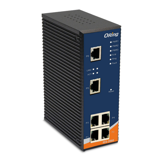
About the IES-2060 / 2042FX Lite-Managed Industrial Switch
Software Features
Hardware Features
Hardware Installation
Installing Switch on DIN-Rail
Mount IES-2042 SERIES on DIN-Rail
Wall Mounting Installation
Hardware Overview
Front Panel
Front Panel Leds
Bottom Panel
Cables
Ethernet Cables
100BASE-TX/10BASE-T Pin Assignments
Fibers
WEB Management
Configuration by Web Browser
About Web-Based Management
Basic Setting
Switch Setting
Admin Password
IP Configuration
SNTP Configuration
Lldp
Backup & Restore
Upgrade Firmware
Redundancy
Fast Recovery Mode
O-Ring
O-Chain
Open-Ring
Rstp
Port Configuration
Port Control
Port Status
Port Alias
Vlan
VLAN Configuration - Port Based
SNMP Configuration
SNMP - Agent Setting
SNMP -Trap Setting
SNMP - SNMP-V3 Setting
System Warning
Syslog Setting
System Event Log
SMTP Setting
Event Selection
Fault Relay Alarm
Save Configuration
Factory Default
System Reboot
Technical Specifications
Advertisement
Quick Links
Download this manual
Industrial
Lite-Managed Ethernet Switch
IES-2042 SERIES User's Manual
Version 2.0
NOV, 2011.
ORing Industrial Networking Corp.
Website: www.oring-networking.com
E-mail:
support@oring-networking.com
Table of
Contents
Previous
Page
Next
Page
1
2
3
4
5
Advertisement
Table of Contents
Need help?
Do you have a question about the IES-2042 Series and is the answer not in the manual?
Ask a question
Questions and answers
Related Manuals for ORiNG IES-2042 Series
Switch ORiNG IES-2060 Series User Manual
Industrial lite-managed ethernet switch (40 pages)
Network Router ORiNG IES-2050A User Manual
Industrial lite-managed ethernet switch (41 pages)
Network Router ORiNG IES-2042PA User Manual
Industrial lite-managed ethernet switch (42 pages)
Network Router ORiNG IES-3082GC User Manual
Industrial managed ethernet switch (101 pages)
Network Router ORiNG IES-3162GC User Manual
Industrial management ethernet switch (104 pages)
Network Router ORiNG IES-3242GC Quick Installation Manual
Managed ethernet switch (2 pages)
Network Router ORiNG IES-180B Quick Installation Manual
(2 pages)
Network Router ORiNG IES-1080A Quick Installation Manual
Industrial unmanaged switch (2 pages)
Network Router ORiNG IES-3000 Series Quick Installation Manual
Industrial managed ethernet switch (2 pages)
Network Router ORiNG IES-3080 Series Quick Installation Manual
Industrial managed ethernet switch (2 pages)
Network Router ORiNG IES-3080 Series User Manual
Industrial managed ethernet switches (112 pages)
Network Router ORiNG IES-3062FX User Manual
Industrial managed ethernet switches (112 pages)
Network Router ORiNG IES-P3073GC Series User Manual
Industrial managed ethernet switch (103 pages)
Network Router ORiNG IES-2042FX User Manual
Industrial lite-managed ethernet switch (42 pages)
Network Router ORiNG iar-120 series User Manual
Iar-120 series ieee 802.11 b/g access point router (61 pages)
Network Router ORiNG IGS-3032GC User Manual
Industrial management ethernet switch (101 pages)
This manual is also suitable for:
Ies-2060
Ies-2042fx
Table of Contents
Print
Rename the bookmark
Delete bookmark?
Delete from my manuals?
Login
Sign In
OR
Sign in with Facebook
Sign in with Google
Upload manual
Upload from disk
Upload from URL


Need help?
Do you have a question about the IES-2042 Series and is the answer not in the manual?
Questions and answers