Table of Contents
Advertisement
Quick Links
40 Class
2-cycle engine
52 Class
4-cycle engine
Or Electric equivalent
VQA09 / VQA091
RADIO CONTROLED ALMOST READY-TO-FLY ENGINE POWERED ALL BALSA PLANE
SPECIFICATIONS
Wingspan
Length
Flying weight
Electric Motor
Glow Engine
Radio
Technische Daten
Spannweite
Länge
Fluggewicht
Elektroantrieb
Verbrennerantrieb
Fernsteuerung
WARNING! This radio controlled model is NOT a toy. If modified or flown carelessly it could go out of controll and
cause serious human injury or property damage. Before flying your airplane, ensure the air field is spacious enough.
Always fly it outdoors in safe areas and seek professional advice if you are unexperienced.
ACHTUNG! Dieses ferngesteuerte Modell ist KEIN Spielzeug! Es ist für fortgeschrittene Modellflugpiloten bestimmt,
die ausreichende Erfahrung im Umgang mit derartigen Modellen besitzen Bei unsachgemäßer Verwendung kann
hoher Personen- und/oder Sachschaden entstehen. Fragen Sie in einem Modellbauverein in Ihrer Nähe um
professionelle Unterstützung, wenn Sie Hilfe im Bau und Betrieb benötigen. Der Zusammenbau dieses Modells ist
durch die vielen Abbildungen selbsterklärend und ist für fortgeschrittene, erfahrene Modellbauer bestimmt.
BUILDING INSTRUCTIONS / MONTAGEANLEITUNG
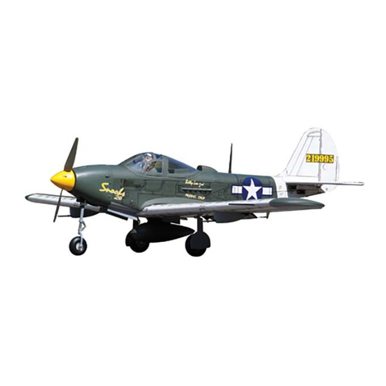
Semi scale model
1580mm
1160mm
2500g
650 Watt (BOOST 40)
6,5cc 2T / 8,5cc 4-T
4 Channel / 4 Servos
1580mm
1160mm
2500g
650 Watt (BOOST 40)
6,5cc 2T / 8,5cc 4T
4 Kanal / 4 Servos
Advertisement
Table of Contents

Subscribe to Our Youtube Channel
Related Manuals for VQ Model VQA09


Summary of Contents for VQ Model VQA09
- Page 1 40 Class 2-cycle engine 52 Class 4-cycle engine Or Electric equivalent BUILDING INSTRUCTIONS / MONTAGEANLEITUNG Semi scale model VQA09 / VQA091 RADIO CONTROLED ALMOST READY-TO-FLY ENGINE POWERED ALL BALSA PLANE SPECIFICATIONS Wingspan 1580mm Length 1160mm Flying weight 2500g Electric Motor...
- Page 2 OPTIONAL ACCESSORIES / BENOTIGTES ZUBEHOR 10.5x6 for .40 - 2 cycle engine 11x6 for .46 - 2 cycle engine 11X7 for .52 - 4 cycle engine Extension for aileron servo Minimum 5 channel radio for airplane with 5 servos 650 Watt Silicone tube .Motor control x1 Brushless motor...
- Page 3 Joining the wing / Flachenverbindung WING TOP-VIEW Secure one end of the thread with adhesive tape Use epoxy glue to bury the opening ! Make sure to glue securely, If not properly glued, a failure in flight may occur. Trial fit each part before gluing . Be certain that there Secure one end of the are no gaps.
-
Page 4: Aileron Linkage
-Switch on the radio (trims Aileron Servo / Querruder servo centered) then mount the ailerons servo horn in neutral position. -The servo horn should be perpendicular to the servo Connector Plastic control horn ....2 ....2 ....2 2x20mm screw Aileron push rod ....4 ..2 Aileron linkage... - Page 5 7- Fixed gear / Landegestange 5/32”(4mm) stopper 4mm collar ..2 WING BOTTOM-VIEW 5/32x1” 1/8x1” 8- Engine mount / Motortrager 4x25mm screw 3x25mm screw ...4 ...4 ! Align the mark on both mounts Blind-nut 1/8”(3mm) nut with the mark on the fuselage ....4 ....4 ! Engine thrust on balk head...
-
Page 6: Fuel Tank Installation
Nose Gear / Bugfahrwerk 1/8x51/64” To rudder servo 3x20mm screw ....4 Blind-nut .....4 ....1 Securely attach the nose gear mount to the fire wall using the four 3x20mm(1/8X51/64”) screws. Slide the nose gear push rod through the nose gear control horn. With the screw hole facing forward, slide the nose gear control horn onto the straight end of the nose gear so the so the steering arm extends in the opposite direction of the nose gear axle. -
Page 7: Electric Motor
- Using a plywood motor mounting plate as a template, mark the fire wall where the 11- Electric Motor four holes are to be drilled (1). - Remove the plywood motor mounting plate and drill a 13/64”(5mm) hole through the fire-wall at each of the four marks marked (2). -
Page 8: Vertical Stabilizers Installation
13- Horizontal Stabilizers installation Cut away only the film both side Spread epoxy on top A’ and bottom A = A’ Cut away only B = B’ the film both Note: When joining the stabilizer it is side extremely important to use plenty of B’... -
Page 9: Control Horn
When you are satisfied with the alignment of the control horn (see 11A and 13) mark the 15- Control horn mounting hole positions with a felt tipped pen or a pencil. Remove the control horn and drill two 2mm (5/64”) holes through the rudder and elevator. Attach the rudder and elevator control horn using two 5/64X15/32”(2x12mm) screws and a back plate. -
Page 10: Bottom View
17- Linkages Rudder rod Elevator rod Elevator rod BOTTOM VIEW Rudder servo Throttle servo Throttle push rod Nose gear push rod Elev.servo 18- Cowling 3/32x13/32” 2.5x10mm..4 1.5mm 1/16” 2-3mm 5/64” 2.5x10mm screw Relieve the cowl to clear the engine head... - Page 11 Try not to make air bubbles, if there are some, carefully puncture sticker (center of bubble) but not model surface with the tip of the knife or sharp pin and squeeze out the air. At curves stretch sticker and apply a little heat so that no ceases occur. Cut off the excess that is produced. 219995 “3 ” VQA09 VQA091...
- Page 12 21- Control surface 15/64”(6mm) 15/64”(6mm) AILERON STROKE 1-3/16”(30mm) 13/32”(10mm) 1-3/16”(30mm) 13/32”(10mm) ELEVATOR STROKE RUDDER STROKE Adjust the travel of the control surfaces to achieve the values stated in the diagrams. These value will be suitable for average flight requirements. Adjust the values to suit your particular needs. WARNING ! Securely install the receiver and power 22- Balance pack, ensuring they will not come loose or rattle during...
Need help?
Do you have a question about the VQA09 and is the answer not in the manual?
Questions and answers