Siemens SINAMICS S120 Configuration Manual
Synchronous motors
Hide thumbs
Also See for SINAMICS S120:
- Function manual (1094 pages) ,
- Diagnostic manual (947 pages) ,
- Manual (848 pages)

Related Manuals for Siemens SINAMICS S120


Summary of Contents for Siemens SINAMICS S120
- Page 1 Configuration Manual 12/2006 Edition 1FK7 Synchronous Motors SINAMICS S120 sinamics...
- Page 3 Foreword Motor Description Application SINAMICS S120 Mechanical data Synchronous Motors 1FK7 Electrical data Configuration Configuration Manual Motor components Technical data and characteristics Dimension drawings Gearbox Appendix (PFK7S), Edition 12.2006 6SN1197-0AD16-0BP1...
- Page 4 Trademarks All names identified by ® are registered trademarks of the Siemens AG. The remaining trademarks in this publication may be trademarks whose use by third parties for their own purposes could violate the rights of the owner.
-
Page 5: Foreword
You will find an overview of the documentation, which is updated on a monthly basis, in the available languages on the Internet under: http://www.siemens.com/motioncontrol Select the menu items "Support" → "Technical Documentation" → "Overview of Publications". The Internet version of DOConCD (DOConWEB) is available at: http://www.automation.siemens.com/doconweb... - Page 6 The EC Declaration of Conformity for the EMC Directive can be found/obtained in the Internet: http://www.support.automation.siemens.com under the Product/Order No. 15257461 at the relevant branch office of the A&D MC Division of Siemens AG. Synchronous Motors 1FK7 Configuration Manual, (PFK7S), Edition 12.2006, 6SN1197-0AD16-0BP1...
- Page 7 Foreword Disposal Motors must be disposed of carefully taking into account domestic and local regulations in the normal recycling process or by returning to the manufacturer. The following must be taken into account when disposing of the motor: • Oil according to the regulations for disposing of old oil •...
- Page 8 Foreword Warning The successful and safe operation of this equipment and motors is dependent on professional transport, storage, installation and mounting as well as careful operator control, service and maintenance. For special versions of the drive units and motors, information and data in the catalogs and quotations additionally apply.
- Page 9 Foreword Note Under field conditions and in dry service areas, SINAMICS units with motors conform to Low-Voltage Directive 73/23/EEC. In configurations specified in the associated EC Declaration of Conformity, SINAMICS units with motors conform to the EMC Directive 89/336/EEC. ESDS instructions Caution An electrostatic-sensitive device (ESDS) is an individual component, integrated circuit, or module that can be damaged by electrostatic fields or discharges.
- Page 10 Information regarding non-Siemens products Notice This document contains recommendations relating to non-Siemens products. Non-Siemens products whose fundamental suitability is familiar to us. It goes without saying that equivalent products from other manufacturers may be used. Our recommendations are to be seen as helpful information, not as requirements or dictates.
-
Page 11: Table Of Contents
Table of contents Foreword ..............................5 Motor Description............................. 15 Features ............................15 Technical features........................16 Selection and Ordering Data......................18 1.3.1 1FK7 Compact motors .........................18 1.3.2 1FK7 High Dynamic motors ......................20 1.3.3 1FK7 Motors on Power Module 1 AC 230 V................22 Application ............................... 25 Environment ..........................25 2.1.1 Mounting position.........................25... - Page 12 1FK7 Compact ..........................92 7.2.2 1FK7 High Dynamic ........................134 1FK7 motors on SINAMICS S120 Power Module with 1 AC 230 V power supply ....156 Cantilever force diagrams ......................172 Dimension drawings ..........................177 1FK7 Compact and High Dynamic motors................178 8.1.1...
- Page 13 Table of contents Motors with planetary gears.......................194 9.2.1 Characteristics of SP+ series.....................194 9.2.1.1 Selection and ordering data .......................196 9.2.2 Characteristics of the LP+ series ....................200 9.2.2.1 Selection and Ordering Data......................202 9.2.3 Compact geared motor 1FK7 DYA ....................203 9.2.3.1 Mounting options........................207 Motors with helical and bevel gearboxes...................208 9.3.1 Characteristics ...........................208...
- Page 14 Table of contents Synchronous Motors 1FK7 Configuration Manual, (PFK7S), Edition 12.2006, 6SN1197-0AD16-0BP1...
-
Page 15: Motor Description
1FK7 motors can be optimally adapted to any application. They therefore also satisfy the permanently increasing demands of state-of-the-art machine generations. 1FK7 motors can be combined with the SINAMICS S120 drive system to create a powerful system with high functionality. The integrated encoder systems for speed and position control can be selected depending on the application. -
Page 16: Technical Features
Motor Description 1.2 Technical features Benefits 1FK7 Compact motors offer: • Space-saving installation thanks to extremely high power/weight ratio • Can be universally used for many applications • Wide range of motors 1FK7 High Dynamic motors offer: • Extremely high dynamic response thanks to low rotor moment of inertia Fields of application •... - Page 17 Motor Description 1.2 Technical features Max. sound pressure level in accordance with EN ISO 1680 1FK701⃞: 55 dB(A) 1FK702⃞: 55 dB(A) 1FK703⃞: 55 dB(A) 1FK704⃞: 55 dB(A) 1FK706⃞: 65 dB(A) 1FK708⃞: 70 dB(A) 1FK710⃞: 70 dB (A) Incremental encoder sin/cos 1 V 2048 S/R Encoder systems, integrated for motors with/without •...
-
Page 18: Selection And Ordering Data
Motor Description 1.3 Selection and Ordering Data Selection and Ordering Data 1.3.1 1FK7 Compact motors Rated Shaft Rated Static Rated Rated current 1FK7 synchronous motor Num- Rotor Weight Compact speed height power torque torque ber of moment of (without natural cooling pole inertia brake) - Page 19 Order no. calc rated at M for M con- cable cross Pre-assembled cable For complete order no., ∆T=100 K ∆T=100 K nector section see “SINAMICS S120” kW/HP Size 1FK7105-5AC71... 10/13.4 6SL312 TE23-0AA. 4 x 2.5 002-5 S31-..1FK7042-5AF71... 0.9/1.2 6SL312 TE13-0AA.
-
Page 20: 1Fk7 High Dynamic Motors
Motor Description 1.3 Selection and Ordering Data 1.3.2 1FK7 High Dynamic motors Rated Shaft Rated Static Rated Rated current 1FK7 High Dynamic Num- Rotor Weight speed height power torque torque synchronous motor ber of moment of (without with natural cooling pole inertia brake) - Page 21 Motor Description 1.3 Selection and Ordering Data Rated Shaft Rated Static Rated Rated current 1FK7 Compact/High Dynamic Num- Rotor Weight synchronous motor speed height power torque torque ber of moment of (without Natural cooling pole inertia brake) Connection to SINAMICS pairs (without 230 V 1 AC...
-
Page 22: 1Fk7 Motors On Power Module 1 Ac 230 V
Motor Description 1.3 Selection and Ordering Data 1.3.3 1FK7 Motors on Power Module 1 AC 230 V Rated Shaft Rated Static Rated Rated current 1FK7 Compact/High Dynamic Num- Rotor Weight speed height power torque torque synchronous motor ber of moment of (without Natural cooling pole... - Page 23 M at M con- cable cross Pre-assembled cable For complete order no., ∆T=100 K ∆T=100 K ∆T=100 K nector section see “SINAMICS S120” kW/HP Size 1FK7032-5AF21... 0.36/0.5 6SL3210 - 1SB12-3UA0 4 x 1.5 002-5 A01-..1FK7033-7AF21... 0.41/0.6 6SL3210 - 1SB12-3UA0 4 x 1.5...
- Page 24 Motor Description 1.3 Selection and Ordering Data Synchronous Motors 1FK7 Configuration Manual, (PFK7S), Edition 12.2006, 6SN1197-0AD16-0BP1...
-
Page 25: Application
Application Environment 2.1.1 Mounting position Table 2-1 Types of construction (accdg. to IEC 60034-7) Name Representation Description IM B5 Standard IM V1 The 1FK7 motors can be used in types of construction IM V1 and IM V3 without special ordering. Note: When configuring the IM V3 type of construction, attention must be paid to the permissible axial forces (weight force of the drive... - Page 26 Application 2.1 Environment Non-thermally insulated mounting The following mounting conditions apply for the specified motor data: Table 2-2 Non-thermally insulated mounting conditions Shaft height Steel plate, width x height x thickness [mm] Mounting surface[m 1FK701⃞ 120 x 100 x 10 0.012 1FK702⃞...
-
Page 27: Cooling
Application 2.1 Environment 2.1.3 Cooling 1FK7 motors are self-cooled. Operating temperature range: -15 °C to +40 °C (without any restrictions). The power loss is dissipated through radiation and natural convection, which means that adequate heat dissipation must be ensured by suitably mounting the motor. All of the Catalog data refer to an ambient temperature of 40 °C, mounted so that the motors are not thermally insulated and an installation altitude up to 1000 m above sea level. -
Page 28: Degree Of Protection
Application 2.1 Environment 2.1.4 Degree of protection The degree of protection designation in accordance with EN 60034-5 and IEC 60034-5 is made using the letters "IP" and two digits (e.g. IP64). The second digit in the degree of protection designation represents the protection against water, the first digit the protection against penetration of foreign matter. -
Page 29: Paint Finish
Application 2.1 Environment Routing cables in a wet/moist environment Notice If the motor is mounted in a humid environment, the power and signal cables must be routed as shown in the following figure. Figure 2-2 Routing cables in a wet/moist environment 2.1.5 Paint finish 1FK7 motors are supplied without a paint finish (1FK701 with paint finish). -
Page 30: Operation Under Vibrational Or Shock Stress Conditions
Application 2.1 Environment 2.1.6 Operation under vibrational or shock stress conditions In order to ensure problem-free operation and a long service life, the vibration values defined in DIN ISO 10816 should not be exceeded. Table 2-5 Vibration values Vibrational velocity V [mm/s] accdg. - Page 31 (up to 0.2 mm). A special bearing is required for this. For use of special bearings, contact your Siemens representative. The permissible axial force can be approximately calculated using the following formula: = 0.35 •...
-
Page 32: Electrical Connections
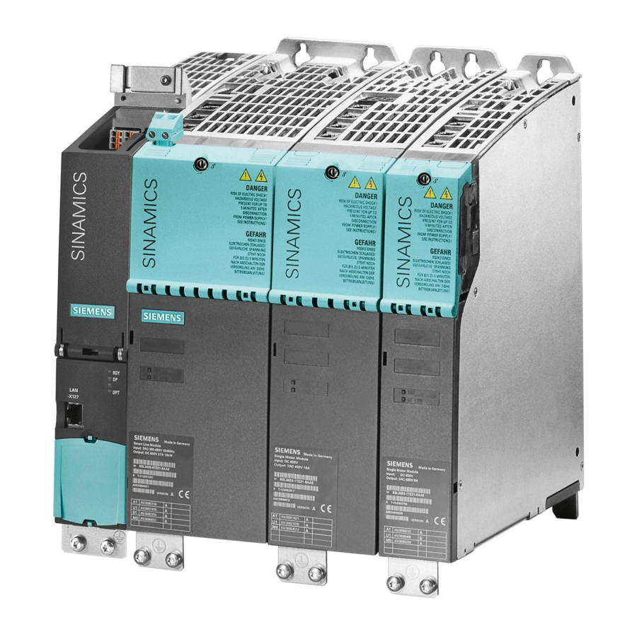
Application 2.2 Electrical connections Electrical connections 2.2.1 Overview of connections Figure 2-4 SINAMICS S120 system overview Synchronous Motors 1FK7 Configuration Manual, (PFK7S), Edition 12.2006, 6SN1197-0AD16-0BP1... -
Page 33: Power Connection
Application 2.2 Electrical connections 2.2.2 Power connection Warning The motors are not designed to be connected directly to the line supply. Connection assignment, power connector at the motor Figure 2-5 Power connection 2.2.3 DRIVE-CLiQ DRIVE-CLiQ is the preferred method for connecting the encoder systems to SINAMICS. Motors with a DRIVE-CLiQ interface can be ordered for this purpose. - Page 34 Motors without DRIVE-CLiQ Motors without DRIVE-CLiQ require a cabinet-mounted sensor module for operation with SINAMICS S120. The sensor modules evaluate the signals from the connected motor encoders or external encoders and convert them to DRIVE-CLiQ. In conjunction with motor encoders, the motor temperature can also be evaluated using sensor modules.
-
Page 35: Rotating The Connectors
Application 2.2 Electrical connections 2.2.4 Rotating the connectors Power connectors, signal connectors, and DRIVE-CLiQ can be rotated to a limited extent. Notice The permissible range of rotation may not be exceeded. In order to guarantee the degree of protection, a max. 10 revolutions are permissible. Do not exceed max. - Page 36 Application 2.2 Electrical connections Synchronous Motors 1FK7 Configuration Manual, (PFK7S), Edition 12.2006, 6SN1197-0AD16-0BP1...
-
Page 37: Mechanical Data
Mechanical data Bearing version The motors have grease-lubricated ball bearings (life lubricated). The bearings are sealed at both ends and designed for a minimum ambient temperature in operation of -15 °C. Note We recommend that the bearings are replaced after approx. 20 000 operating hours, however, at the latest after 5 years. - Page 38 Mechanical data Synchronous Motors 1FK7 Configuration Manual, (PFK7S), Edition 12.2006, 6SN1197-0AD16-0BP1...
-
Page 39: Electrical Data
Electrical data Torque-speed characteristic The permissible operating range is limited by thermal, mechanical, and electromagnetic boundaries. Figure 4-1 Torque characteristics of synchronous motors Permissible temperature range, 100 K-, 60 K-values The temperature rise of the motor is caused by the losses generated in the motor (current-dependent losses, no-load losses, friction losses). -
Page 40: Voltage Limiting Characteristics
Electrical data 4.2 Voltage limiting characteristics Torque characteristics of motor The maximum permissible torque is dependent on the permissible overtemperature and, thus, on the duty. To adhere to the temperature limits, the torque must be reduced as the speed increases, starting from static torque M The characteristic curves are specified for continuous operation S1 (100 K), S1 (60 K) duty and periodic intermittent operation S3-25%, S3-40%, S3-60% duty with a cycle time of 10 minutes, except for small motors, for which a cycle time of 1 minute is specified and noted... - Page 41 Electrical data 4.2 Voltage limiting characteristics Converter output voltage The converter output voltages differ according to the converter type and supply voltage. Table 4-2 Converter voltages Converter type Infeed Supply DC link voltage Output voltage module voltage supply DC link SINAMICS S 120 400 V 600 V...
- Page 42 Electrical data 4.2 Voltage limiting characteristics The characteristic curve is plotted for each armature circuit in a separate data sheet. The torque-speed diagrams for different converter output voltages are then assigned to each data sheet. Note The voltage limit characteristic of a motor with 6000 RPM rated speed lies far above that of the same motor type with 2000 RPM.
- Page 43 Electrical data 4.2 Voltage limiting characteristics Calculating the new limit torque with the new limiting characteristic • The value M is read-off from the limiting characteristic curve for U (value at the rated limit speed). Figure 4-3 Offset of voltage limiting characteristic from U to U mot new The voltage limiting characteristic curve specified for U...
- Page 44 Electrical data 4.2 Voltage limiting characteristics Example of offset of voltage limiting characteristic curve without field weakening Motor 1FK7032-5AK71; k = 45 V/1000 RPM = 290 V; calculated with U = 425 V mot, new ∙ nN/1000; U = 45 ∙ 6000/1000 = 270 V Condition: U >...
-
Page 45: Field Weakening Mode
4.3 Field weakening mode Field weakening mode The SINAMICS S120 converter injects a field weakening current which means that the motor can operate above the voltage limiting characteristic without field weakening. The method used by the converter to inject the field weakening current has a significant influence on the curve characteristic. - Page 46 The motor must not be operated at speeds higher than unless additional protective max Inv measures are implemented. Siemens AG will not accept liability for any type of damage resulting from this particular cause. Synchronous Motors 1FK7 Configuration Manual, (PFK7S), Edition 12.2006, 6SN1197-0AD16-0BP1...
-
Page 47: Definitions
Electrical data 4.4 Definitions Definitions Rated speed n The characteristic speed range for the motor is defined in the speed-torque diagram by the rated speed. Number of poles 2p Number of magnetic north and south poles on the rotor. p is the number of pole pairs. Rated torque M Thermally permissible continuous torque in S1 duty at the rated motor speed. - Page 48 Electrical data 4.4 Definitions Optimum operating point Operating point at which the maximum continuous output of the motor is normally provided at high efficiency (see figure below). Figure 4-5 Optimum operating point Optimum speed n Speed at which the optimum motor power is output. If the rated speed is less than the optimum speed, the rated speed is indicated.
- Page 49 Electrical data 4.4 Definitions Maximum speed n The maximum permissible operating speed n is the lesser of the maximum mechanically permissible speed and the maximum permissible speed at the converter. Maximum permissible speed (mechanical) n The maximum mechanically permissible speed is n .
- Page 50 Electrical data 4.4 Definitions Voltage constant k (value at 20 °C rotor temperature) Value of the induced motor voltage at a speed of 1000 RPM and a rotor temperature of 20 °C. The phase-to-phase RMS motor terminal voltage is specified for 1FK7 motors. Winding resistance R at 20 °C winding temperature The resistance of a phase at a winding temperature of 20 °C is specified.
- Page 51 Electrical data 4.4 Definitions Maximum converter current I max Inv RMS converter output current (per phase) that can be supplied temporarily by the recommended motor module Maximum torque (limited by converter) M max Inv The maximum torque that can be applied (temporarily) for operation on the recommended motor module.
- Page 52 Electrical data 4.4 Definitions Tolerance data (data going beyond this are subject to a specific measuring accuracy) Table 4-3 Tolerance data in the motor list data Motor list data Typ. value Theoretical value Stall current ± 3 % ± 7,5 % Electrical time constant ±...
-
Page 53: Configuration
Configuration Engineering software 5.1.1 SIZER engineering tool Overview Figure 5-1 SIZER Synchronous Motors 1FK7 Configuration Manual, (PFK7S), Edition 12.2006, 6SN1197-0AD16-0BP1... - Page 54 Configuration 5.1 Engineering software The SIZER configuration tool provides an easy-to-use means of configuring the SINAMICS and MICROMASTER 4 drive families, as well as the SINUMERIK solution line CNC control and SIMOTION Motion Control system. It provides support when setting up the technologies involved in the hardware and firmware components required for a drive task.
- Page 55 Configuration 5.1 Engineering software Minimum hardware and software requirements • PG or PC with Pentium™ II 400 MHz (Windows™ 2000), Pentium™ III 500 MHz (Windows™ XP) • 256 MB RAM (512 MB recommended) • At least 1150 MB free hard disk space, additional 100 MB free hard disk space on Windows system drive •...
-
Page 56: Starter Drive/Commissioning Software
Configuration 5.1 Engineering software 5.1.2 STARTER drive/commissioning software Overview Figure 5-2 STARTER The easy-to-use STARTER drive/commissioning tool can be used for: • Commissioning, • Optimization, and • Diagnostics This software can be operated either as a standalone PC application or can be integrated into the SCOUT engineering system (with SIMOTION) or STEP 7 (with Drive ES Basic). - Page 57 Configuration 5.1 Engineering software Wizards are used to navigate users when drives are being commissioning for the first time; these Wizards make all of the basic settings in the drive. This enables a drive to be up and running after only setting a small number of parameters within the drive configuration process.
-
Page 58: Engineering System Drive Es
Figure 5-3 Drive ES Drive ES is the engineering system used to easily integrate Siemens drive technology into the SIMATIC automation world easily, efficiently and cost-effectively in terms of communication, configuration and data management. The STEP 7 Manager user interface provides the basis for this procedure. - Page 59 This means that the drives can be operated from the PCS 7 process control system. For further information please visit us on the Internet at: http://www.siemens.com/drivesolutions Synchronous Motors 1FK7 Configuration Manual, (PFK7S), Edition 12.2006, 6SN1197-0AD16-0BP1...
- Page 60 Configuration 5.1 Engineering software Selection and Ordering Data Table 5-1 Selection and ordering data for Drive ES engineering system Description Order No. (MLFB) Drive ES Basic V 5.4 • Engineering software for integration of drives into Totally Integrated Automation • Prerequisites: STEP 7 V 5.3 SP 3, or higher •...
-
Page 61: Sinamics Configuring Sequence, Suppress Title
Configuration 5.2 SINAMICS configuring sequence, suppress title SINAMICS configuring sequence, suppress title The function description of the machine provides the basis when engineering the drive application. The definition of the components is based on physical interdependencies and is usually carried-out as follows: step Description of the engineering activity Refer to... -
Page 62: Dimensioning
Configuration 5.3 Dimensioning Dimensioning 5.3.1 1. Clarification of the type of drive The motor is selected on the basis of the required torque, which is defined by the application, e.g. traveling drives, hoisting drives, test stands, centrifuges, paper and rolling mill drives, feed drives or main spindle drives. -
Page 63: Definition Of The Load Event, Calculation Of Max. Load Torque
Configuration 5.3 Dimensioning Figure 5-4 Limit curves for synchronous motors 5.3.2 2. Definition of the load event, calculation of max. load torque Load duty cycles The motor is selected based on the load which is specified by the application. Different characteristic curves must be used for different load events. - Page 64 Configuration 5.3 Dimensioning • It should be noted that the maximum permissible motor torque on synchronous motors at higher speeds is reduced as a result of the voltage limiting characteristic. In addition, a margin of 10% below the voltage limiting characteristic should be maintained to safeguard against voltage fluctuations.
- Page 65 Configuration 5.3 Dimensioning Load duty cycles with varying on period As well as continuous duty (S1), standard intermittent duty types (S3) are also defined for load duty cycles with varying on periods. This involves operation that comprises a sequence of similar load cycles, each of which comprises a time with constant load and an off period. Figure 5-6 S1 duty (continuous operation) Figure 5-7...
- Page 66 Configuration 5.3 Dimensioning Load cycle A load duty cycle defines the characteristics of the motor speed and the torque with respect to time. Figure 5-8 Example of a load duty cycle A load torque is specified for each time period. In addition to the load torque, the average load moment of inertia and motor moment of inertia must be taken into account for acceleration.
- Page 67 Configuration 5.3 Dimensioning Motor moment of inertia Gearbox moment of inertia Load moment of inertia load Load speed Load Gear ratio η Gearbox efficiency Load torque load Frictional torque Cycle time, clock cycle time A; E Initial value, final value in time slice Δ ON period ∆t Time interval...
-
Page 68: Specification Of The Motor
Configuration 5.3 Dimensioning 5.3.3 3. Specification of the motor Through variation, it is now possible to identify a motor which meets the requirements of the application. In a second step, a check is made as to whether the thermal limits are maintained. To do this, the motor current at the base load must be calculated. -
Page 69: Motor Components
Motor components Thermal motor protection A temperature-dependent resistor is integrated as temperature sensor to monitor the motor temperature. Table 6-1 Features and technical data Type KTY 84 (PTC thermistor) Resistance when cold (20°C) approx. 580 Ohm Resistance when hot (100°C) approx. - Page 70 Motor components 6.1 Thermal motor protection Caution The integrated temperature sensor protects the synchronous against an overload condition Shaft height 11 to 48 to 2 • I and speed <> 0 0 (60 K) From shaft height 63 up to 4∙ I and speed <>...
-
Page 71: Encoder (Option)
Motor components 6.2 Encoder (option) Encoder (option) 6.2.1 Encoder overview The encoder is selected in the motor Order No. (MLFB) using the appropriate letter at the 14th position. The letter ID at the 14th position of the Order No. (MLFB) differs for motors with an without DRIVE-CLiQ. -
Page 72: Encoder Connection For Motors With Drive-Cliq
Motor components 6.2 Encoder (option) 6.2.2 Encoder connection for motors with DRIVE-CLiQ Motors with DRIVE-CLiQ have a sensor module that includes the encoder evaluation, the motor temperature sensing and an electronic rating plate. This sensor module instead of the signal connector and has a 10-pin RJ45-plus socket. Warning The sensor module contains motor and encoder-specific data as well as an electronic rating plate. -
Page 73: Incremental Encoders
Motor components 6.2 Encoder (option) 6.2.4 Incremental encoders Function: • Angular measuring system for commutation • Speed actual value sensing • Indirect incremental measuring system for the position control loop • One zero pulse (reference mark) per revolution Table 6-4 Technical data for incremental encoder sin/cos 1 Vpp Properties Incremental encoders... - Page 74 Motor components 6.2 Encoder (option) Connection assignment for 17-pin flange-mounted socket with pin contacts Table 6-5 Connection assignment, 17-pin flange-mounted socket PIN No. Description of the signals When viewing the plug-in side (pins) Connector size 1 for Connector size 0.5 for 1FK702⃞...
-
Page 75: Absolute Value Encoder
Motor components 6.2 Encoder (option) 6.2.5 Absolute value encoder Function: • Angular measuring system for the commutation • Speed actual value sensing • Indirect absolute measuring system for the position control loop Table 6-7 Technical data, absolute value encoder Properties Absolute encoders Absolute encoders Simple absolute value... - Page 76 Motor components 6.2 Encoder (option) Connection assignment for 17-pin flange-mounted socket with pin contacts Table 6-8 Connection assignment, 17-pin flange-mounted socket PIN No. Description of the signals When viewing the plug-in side (pins) Connector size 1 for Connector size 0.5 for 1FK702⃞...
-
Page 77: Resolvers
Motor components 6.2 Encoder (option) 6.2.6 Resolvers Function: • Angular measuring system for the commutation • Speed actual value sensing • Indirect incremental measuring system for the position control loop Table 6-10 Technical data, resolvers Properties Resolver Mech. limiting speed 15 000 RPM Excitation voltage 5 V (rms) to 13 V (rms) - Page 78 Motor components 6.2 Encoder (option) Connection assignment for 12/17-pin flange socket with pin contacts Table 6-11 Connection assignment for flange socket, 12-pin PIN No. Description of the signals When viewing the plug-in side (pins) 12-pin 17-pin Connector size 1 for Connector size 0.5 for 1FK702⃞...
-
Page 79: Holding Brake (Option)
Motor components 6.3 Holding brake (option) Holding brake (option) 6.3.1 Properties • The integrated or mounted holding brake is used to clamp the motor shaft when the motor is at a standstill. The holding brake is not a working brake that is used to brake a motor that is still rotating. -
Page 80: Permanent-Magnet Brake
Motor components 6.3 Holding brake (option) 6.3.3 Permanent-magnet brake Mode of operation of a permanent-magnet brake The magnetic field of the permanent magnets results in a pulling force on the brake armature disk. This means that in the no-current condition, the brake is closed and the motor shaft is held. -
Page 81: Protective Circuitry For The Brake
Motor components 6.3 Holding brake (option) 6.3.5 Protective circuitry for the brake Caution In order to avoid overvoltages when shutting down and the possible negative impact on the plant or system environment, a protective circuit must be integrated into the brake feeder cable (refer to Fig. - Page 82 Motor components 6.3 Holding brake (option) Figure 6-5 Terminology (time) for holding operation Important information and instructions when installing the connecting cable The brake connecting cable is included in the power cable. The insulation between the power and brake connection is dimensioned for basic insulation (VDE 600 V/1000 V UL). The relay K1, located between the coil and contact, must also have basic insulation in order to protect the internal logic voltage (PELV=Protective Extra Low Voltage).
-
Page 83: Technical Data Of The Holding Brake
Motor components 6.3 Holding brake (option) 6.3.6 Technical data of the holding brake Table 6-14 Technical data of the holding brakes used for 1FK7 motors Motor type Brake type Holding torque Direct current Opening time Closing time Highest at 120 °C at 20 °C switched with varistor... -
Page 84: Brake Resistances (Armature Short-Circuit Braking)
Motor components 6.4 Brake resistances (armature short-circuit braking) Brake resistances (armature short-circuit braking) 6.4.1 Function description For transistor PWM converters, when the DC link voltage values are exceeded or if the electronics fails, then electrical braking is no longer possible. If the drive which is coasting down, can represent a potential hazard, then the motor can be braked by short-circuiting the armature. -
Page 85: Rating
Motor components 6.4 Brake resistances (armature short-circuit braking) Ordering address Frizlen GmbH & Co. KG Gottlieb-Daimler-Str. 61, 71711 Murr Germany Phone: +49 (0) 7144 / 8100 - 0 Fax: +40 (0) 7144 / 2076 - 30 E-mail: info@frizlen.com Internet at: www.frizlen.com Note We cannot accept any liability for the quality and properties/features of third-party products. - Page 86 Motor components 6.4 Brake resistances (armature short-circuit braking) Notice When determining the run-on distance, then, for example, the friction (taken into account as allowance in M )of the mechanical transmission elements and the switching delay times of the contactors must be taken into consideration. In order to prevent mechanical damage, mechanical end stops should be provided at the end of the absolute traversing range of the machine axes.
-
Page 87: Dimensioning Of Braking Resistors
Motor components 6.4 Brake resistances (armature short-circuit braking) 6.4.4 Dimensioning of braking resistors The correct dimensioning ensures an optimum braking time. The braking torques which are obtained are also listed in the tables. These data apply to braking operations from the rated speed and moment of inertia J . - Page 88 Motor components 6.4 Brake resistances (armature short-circuit braking) Table 6-16 Dynamic braking for 1FK7 HD Motor type Braking Average braking torque Max. braking RMS braking current resistor, torque M [Nm] br max br rms br rms external [Nm] Without With external Without With external [Ω]...
-
Page 89: Drive Coupling
Function description Function description After investigating various drive-out couplings for servomotors in conjunction with Siemens drive converters, it was seen, that in many cases, the drive-out couplings were the cause of vibration problems. In order to achieve optimum drive-out characteristics, ROTEX Ⓡ... -
Page 90: Technical Data For The Couplings
Motor components 6.5 Drive coupling 6.5.2 Technical data for the couplings Table 6-18 Assignment of the drive couplings to the motors [mm] Rotex Transferable torques with 80 or 92 [Nm] Ⓡ Sh A Motor 1FK7 Type pinion [Nm] [Nm] Kmax 1FK7022–... -
Page 91: Technical Data And Characteristics
Technical data and characteristics Introduction The rating data specified in the tables refer to V = 400 V, supply rms Active Line Module, characteristic [b]. Note The voltage limiting characteristics [a], [b], [c] refer to the converter output voltage as a function of the supply voltage. -
Page 92: 1Fk7 Motors On Sinamics S120 With 3 Ac 400/480 V Power Supply
Technical data and characteristics 7.2 1FK7 motors on SINAMICS S120 with 3 AC 400/480 V power supply 1FK7 motors on SINAMICS S120 with 3 AC 400/480 V power supply 7.2.1 1FK7 Compact Table 7-1 1FK7011 CT Technical data Code Units –5AK71... - Page 93 Technical data and characteristics 7.2 1FK7 motors on SINAMICS S120 with 3 AC 400/480 V power supply Figure 7-1 1FK7011-5AK71 SINAMICS SLM 400 V SINAMICS ALM 400 V SINAMICS SLM 480 V Synchronous Motors 1FK7 Configuration Manual, (PFK7S), Edition 12.2006, 6SN1197-0AD16-0BP1...
- Page 94 Technical data and characteristics 7.2 1FK7 motors on SINAMICS S120 with 3 AC 400/480 V power supply Table 7-2 1FK7015 CT Technical data Code Unit –5AK71 Configuration data Rated speed 6000 No. of poles Rated torque (100 K) 0.16 N (100 K) Rated current (100 K) 0.85...
- Page 95 Technical data and characteristics 7.2 1FK7 motors on SINAMICS S120 with 3 AC 400/480 V power supply Figure 7-2 1FK7015-5AK71 SINAMICS SLM 400 V SINAMICS ALM 400 V SINAMICS SLM 480 V Synchronous Motors 1FK7 Configuration Manual, (PFK7S), Edition 12.2006, 6SN1197-0AD16-0BP1...
- Page 96 Technical data and characteristics 7.2 1FK7 motors on SINAMICS S120 with 3 AC 400/480 V power supply Table 7-3 1FK7022 CT Technical data Code Unit –5AK71 Configuration data Rated speed 6000 No. of poles Rated torque (100 K) N (100 K)
- Page 97 Technical data and characteristics 7.2 1FK7 motors on SINAMICS S120 with 3 AC 400/480 V power supply Figure 7-3 1FK7022 - 5AK71 SINAMICS SLM 400 V SINAMICS ALM 400 V SINAMICS SLM 480 V Synchronous Motors 1FK7 Configuration Manual, (PFK7S), Edition 12.2006, 6SN1197-0AD16-0BP1...
- Page 98 Technical data and characteristics 7.2 1FK7 motors on SINAMICS S120 with 3 AC 400/480 V power supply Table 7-4 1FK7032 CT Technical data Code Unit –5AK71 Configuration data Rated speed 6000 No. of poles Rated torque (100 K) N (100 K)
- Page 99 Technical data and characteristics 7.2 1FK7 motors on SINAMICS S120 with 3 AC 400/480 V power supply Figure 7-4 1FK7032-5AK71 SINAMICS SLM 400 V SINAMICS ALM 400 V SINAMICS SLM 480 V Synchronous Motors 1FK7 Configuration Manual, (PFK7S), Edition 12.2006, 6SN1197-0AD16-0BP1...
- Page 100 Technical data and characteristics 7.2 1FK7 motors on SINAMICS S120 with 3 AC 400/480 V power supply Table 7-5 1FK7034 CT Technical data Code Unit –5AK71 Configuration data Rated speed 6000 No. of poles Rated torque (100 K) N (100 K)
- Page 101 Technical data and characteristics 7.2 1FK7 motors on SINAMICS S120 with 3 AC 400/480 V power supply 1000 2000 3000 4000 5000 6000 7000 8000 9000 1000 2000 3000 4000 5000 6000 7000 8000 9000 Figure 7-5 1FK7034-5AK71 SINAMICS SLM 400 V...
- Page 102 Technical data and characteristics 7.2 1FK7 motors on SINAMICS S120 with 3 AC 400/480 V power supply Table 7-6 1FK7040 CT Technical data Code Unit –5AK71 Configuration data Rated speed 6000 No. of poles Rated torque (100 K) N (100 K)
- Page 103 Technical data and characteristics 7.2 1FK7 motors on SINAMICS S120 with 3 AC 400/480 V power supply Figure 7-6 1FK7040-5AK71 SINAMICS SLM 400 V SINAMICS ALM 400 V SINAMICS SLM 480 V Synchronous Motors 1FK7 Configuration Manual, (PFK7S), Edition 12.2006, 6SN1197-0AD16-0BP1...
- Page 104 Technical data and characteristics 7.2 1FK7 motors on SINAMICS S120 with 3 AC 400/480 V power supply Table 7-7 1FK7042 CT Technical data Code Unit –5AF71 Configuration data Rated speed 3000 No. of poles Rated torque (100 K) N (100 K) Rated current (100 K) 1.95...
- Page 105 Technical data and characteristics 7.2 1FK7 motors on SINAMICS S120 with 3 AC 400/480 V power supply Figure 7-7 1FK7042-5AF71 SINAMICS SLM 400 V SINAMICS ALM 400 V SINAMICS SLM 480 V Synchronous Motors 1FK7 Configuration Manual, (PFK7S), Edition 12.2006, 6SN1197-0AD16-0BP1...
- Page 106 Technical data and characteristics 7.2 1FK7 motors on SINAMICS S120 with 3 AC 400/480 V power supply Table 7-8 1FK7042 CT Technical data Code Unit –5AK71 Configuration data Rated speed 6000 No. of poles Rated torque (100 K) N (100 K) Rated current (100 K) 2.45...
- Page 107 Technical data and characteristics 7.2 1FK7 motors on SINAMICS S120 with 3 AC 400/480 V power supply Figure 7-8 1FK7042-5AK71 SINAMICS SLM 400 V SINAMICS ALM 400 V SINAMICS SLM 480 V Synchronous Motors 1FK7 Configuration Manual, (PFK7S), Edition 12.2006, 6SN1197-0AD16-0BP1...
- Page 108 Technical data and characteristics 7.2 1FK7 motors on SINAMICS S120 with 3 AC 400/480 V power supply Table 7-9 1FK7060 CT Technical data Code Unit –5AF71 Configuration data Rated speed 3000 No. of poles Rated torque (100 K) N (100 K)
- Page 109 Technical data and characteristics 7.2 1FK7 motors on SINAMICS S120 with 3 AC 400/480 V power supply Figure 7-9 1FK7060-5AF71 SINAMICS SLM 400 V SINAMICS ALM 400 V SINAMICS SLM 480 V Synchronous Motors 1FK7 Configuration Manual, (PFK7S), Edition 12.2006, 6SN1197-0AD16-0BP1...
- Page 110 Technical data and characteristics 7.2 1FK7 motors on SINAMICS S120 with 3 AC 400/480 V power supply Table 7-10 1FK7060 CT Technical data Code Unit –5AH71 Configuration data Rated speed 4500 No. of poles Rated torque (100 K) N (100 K)
- Page 111 Technical data and characteristics 7.2 1FK7 motors on SINAMICS S120 with 3 AC 400/480 V power supply Figure 7-10 1FK7060-5AH71 SINAMICS SLM 400 V SINAMICS ALM 400 V SINAMICS SLM 480 V Synchronous Motors 1FK7 Configuration Manual, (PFK7S), Edition 12.2006, 6SN1197-0AD16-0BP1...
- Page 112 Technical data and characteristics 7.2 1FK7 motors on SINAMICS S120 with 3 AC 400/480 V power supply Table 7-11 1FK7063 CT Technical data Code Unit –5AF71 Configuration data Rated speed 3000 No. of poles Rated torque (100 K) N (100 K)
- Page 113 Technical data and characteristics 7.2 1FK7 motors on SINAMICS S120 with 3 AC 400/480 V power supply Figure 7-11 1FK7063-5AF71 SINAMICS SLM 400 V SINAMICS ALM 400 V SINAMICS SLM 480 V Synchronous Motors 1FK7 Configuration Manual, (PFK7S), Edition 12.2006, 6SN1197-0AD16-0BP1...
- Page 114 Technical data and characteristics 7.2 1FK7 motors on SINAMICS S120 with 3 AC 400/480 V power supply Table 7-12 1FK7063 CT Technical data Code Unit –5AH71 Configuration data Rated speed 4500 No. of poles Rated torque (100 K) N (100 K)
- Page 115 Technical data and characteristics 7.2 1FK7 motors on SINAMICS S120 with 3 AC 400/480 V power supply Figure 7-12 1FK7063-5AH71 SINAMICS SLM 400 V SINAMICS ALM 400 V SINAMICS SLM 480 V Synchronous Motors 1FK7 Configuration Manual, (PFK7S), Edition 12.2006, 6SN1197-0AD16-0BP1...
- Page 116 Technical data and characteristics 7.2 1FK7 motors on SINAMICS S120 with 3 AC 400/480 V power supply Table 7-13 1FK7080 CT Technical data Code Units –5AF71 Engineering data Rated speed 3000 No. of poles Rated torque (100 K) N (100 K)
- Page 117 Technical data and characteristics 7.2 1FK7 motors on SINAMICS S120 with 3 AC 400/480 V power supply Figure 7-13 1FK7080-5AF71 SINAMICS SLM 400 V SINAMICS ALM 400 V SINAMICS SLM 480 V Synchronous Motors 1FK7 Configuration Manual, (PFK7S), Edition 12.2006, 6SN1197-0AD16-0BP1...
- Page 118 Technical data and characteristics 7.2 1FK7 motors on SINAMICS S120 with 3 AC 400/480 V power supply Table 7-14 1FK7080 CT Technical data Code Unit –5AH71 Engineering data Rated speed 4500 No. of poles Rated torque (100 K) N (100 K)
- Page 119 Technical data and characteristics 7.2 1FK7 motors on SINAMICS S120 with 3 AC 400/480 V power supply Figure 7-14 1FK7080-5AH71 SINAMICS SLM 400 V SINAMICS ALM 400 V SINAMICS SLM 480 V Synchronous Motors 1FK7 Configuration Manual, (PFK7S), Edition 12.2006, 6SN1197-0AD16-0BP1...
- Page 120 Technical data and characteristics 7.2 1FK7 motors on SINAMICS S120 with 3 AC 400/480 V power supply Table 7-15 1FK7083 CT Technical data Code Unit –5AF71 Engineering data Rated speed 3000 No. of poles Rated torque (100 K) 10.5 N (100 K)
- Page 121 Technical data and characteristics 7.2 1FK7 motors on SINAMICS S120 with 3 AC 400/480 V power supply Figure 7-15 1FK7083-5AF71 SINAMICS SLM 400 V SINAMICS ALM 400 V SINAMICS SLM 480 V Synchronous Motors 1FK7 Configuration Manual, (PFK7S), Edition 12.2006, 6SN1197-0AD16-0BP1...
- Page 122 Technical data and characteristics 7.2 1FK7 motors on SINAMICS S120 with 3 AC 400/480 V power supply Table 7-16 1FK7083 CT Technical data Code Unit –5AH71 Engineering data Rated speed 4500 No. of poles Rated torque (100 K) N (100 K)
- Page 123 Technical data and characteristics 7.2 1FK7 motors on SINAMICS S120 with 3 AC 400/480 V power supply Figure 7-16 1FK7083-5AH71 SINAMICS SLM 400 V SINAMICS ALM 400 V SINAMICS SLM 480 V Synchronous Motors 1FK7 Configuration Manual, (PFK7S), Edition 12.2006, 6SN1197-0AD16-0BP1...
- Page 124 Technical data and characteristics 7.2 1FK7 motors on SINAMICS S120 with 3 AC 400/480 V power supply Table 7-17 1FK7100 CT Technical data Code Unit –5AF71 Configuration data Rated speed 3000 No. of poles Rated torque (100 K) N (100 K)
- Page 125 Technical data and characteristics 7.2 1FK7 motors on SINAMICS S120 with 3 AC 400/480 V power supply max Inv S3-25% S3-40% S3-60% S1 (60K) S1 (100K) 1000 2000 3000 4000 5000 6000 max Inv S3-25% S3-40% S3-60% S1 (60K) S1 (100K)
- Page 126 Technical data and characteristics 7.2 1FK7 motors on SINAMICS S120 with 3 AC 400/480 V power supply Table 7-18 1FK7101 CT Technical data Code Unit –5AF71 Configuration data Rated speed 3000 No. of poles Rated torque (100 K) 15.5 N (100 K) Rated current (100 K) 11.8...
- Page 127 Technical data and characteristics 7.2 1FK7 motors on SINAMICS S120 with 3 AC 400/480 V power supply Figure 7-18 1FK7101-5AF71 SINAMICS SLM 400 V SINAMICS ALM 400 V SINAMICS SLM 480 V Synchronous Motors 1FK7 Configuration Manual, (PFK7S), Edition 12.2006, 6SN1197-0AD16-0BP1...
- Page 128 Technical data and characteristics 7.2 1FK7 motors on SINAMICS S120 with 3 AC 400/480 V power supply Table 7-19 1FK7103 CT Technical data Code Unit –5AF71 Configuration data Rated speed 3000 No. of poles Rated torque (100 K) N (100 K)
- Page 129 Technical data and characteristics 7.2 1FK7 motors on SINAMICS S120 with 3 AC 400/480 V power supply Figure 7-19 1FK7103-5AF71 SINAMICS SLM 400 V SINAMICS ALM 400 V SINAMICS SLM 480 V Synchronous Motors 1FK7 Configuration Manual, (PFK7S), Edition 12.2006, 6SN1197-0AD16-0BP1...
- Page 130 Technical data and characteristics 7.2 1FK7 motors on SINAMICS S120 with 3 AC 400/480 V power supply Table 7-20 1FK7105 CT Technical data Code Unit –5AC71 Configuration data Rated speed 2000 No. of poles Rated torque (100 K) N (100 K)
- Page 131 Technical data and characteristics 7.2 1FK7 motors on SINAMICS S120 with 3 AC 400/480 V power supply Figure 7-20 1FK7105-5AC71 SINAMICS SLM 400 V SINAMICS ALM 400 V SINAMICS SLM 480 V Synchronous Motors 1FK7 Configuration Manual, (PFK7S), Edition 12.2006, 6SN1197-0AD16-0BP1...
- Page 132 Technical data and characteristics 7.2 1FK7 motors on SINAMICS S120 with 3 AC 400/480 V power supply Table 7-21 1FK7105 CT Technical data Code Unit –5AF71 Configuration data Rated speed 3000 No. of poles Rated torque (100 K) N (100 K)
- Page 133 Technical data and characteristics 7.2 1FK7 motors on SINAMICS S120 with 3 AC 400/480 V power supply Figure 7-21 1FK7105-5AF71 SINAMICS SLM 400 V SINAMICS ALM 400 V SINAMICS SLM 480 V Synchronous Motors 1FK7 Configuration Manual, (PFK7S), Edition 12.2006, 6SN1197-0AD16-0BP1...
-
Page 134: 1Fk7 High Dynamic
Technical data and characteristics 7.2 1FK7 motors on SINAMICS S120 with 3 AC 400/480 V power supply 7.2.2 1FK7 High Dynamic Table 7-22 1FK7033 HD Technical data Code Unit –7AK71 Configuration data Rated speed 6000 No. of poles Rated torque (100 K) - Page 135 Technical data and characteristics 7.2 1FK7 motors on SINAMICS S120 with 3 AC 400/480 V power supply Figure 7-22 1FK7033-7AK71 SINAMICS SLM 400 V SINAMICS ALM 400 V SINAMICS SLM 480 V Synchronous Motors 1FK7 Configuration Manual, (PFK7S), Edition 12.2006, 6SN1197-0AD16-0BP1...
- Page 136 Technical data and characteristics 7.2 1FK7 motors on SINAMICS S120 with 3 AC 400/480 V power supply Table 7-23 1FK7043 HD Technical data Code Unit –7AH71 Configuration data Rated speed 4500 No. of poles Rated torque (100 K) N (100 K)
- Page 137 Technical data and characteristics 7.2 1FK7 motors on SINAMICS S120 with 3 AC 400/480 V power supply Figure 7-23 1FK7043-7AH71 SINAMICS SLM 400 V SINAMICS ALM 400 V SINAMICS SLM 480 V Synchronous Motors 1FK7 Configuration Manual, (PFK7S), Edition 12.2006, 6SN1197-0AD16-0BP1...
- Page 138 Technical data and characteristics 7.2 1FK7 motors on SINAMICS S120 with 3 AC 400/480 V power supply Table 7-24 1FK7043 HD Technical data Code Unit –7AK71 Configuration data Rated speed 6000 No. of poles Rated torque (100 K) N (100 K)
- Page 139 Technical data and characteristics 7.2 1FK7 motors on SINAMICS S120 with 3 AC 400/480 V power supply Figure 7-24 1FK7043-7AK71 SINAMICS SLM 400 V SINAMICS ALM 400 V SINAMICS SLM 480 V Synchronous Motors 1FK7 Configuration Manual, (PFK7S), Edition 12.2006, 6SN1197-0AD16-0BP1...
- Page 140 Technical data and characteristics 7.2 1FK7 motors on SINAMICS S120 with 3 AC 400/480 V power supply Table 7-25 1FK7044 HD Technical data Code Unit –7AF71 Configuration data Rated speed 3000 No. of poles Rated torque (100 K) N (100 K)
- Page 141 Technical data and characteristics 7.2 1FK7 motors on SINAMICS S120 with 3 AC 400/480 V power supply Figure 7-25 1FK7044-7AF71 SINAMICS SLM 400 V SINAMICS ALM 400 V SINAMICS SLM 480 V Synchronous Motors 1FK7 Configuration Manual, (PFK7S), Edition 12.2006, 6SN1197-0AD16-0BP1...
- Page 142 Technical data and characteristics 7.2 1FK7 motors on SINAMICS S120 with 3 AC 400/480 V power supply Table 7-26 1FK7044 HD Technical data Code Unit –7AH71 Configuration data Rated speed 4500 No. of poles Rated torque (100 K) N (100 K)
- Page 143 Technical data and characteristics 7.2 1FK7 motors on SINAMICS S120 with 3 AC 400/480 V power supply Figure 7-26 1FK7044-7AH71 SINAMICS SLM 400 V SINAMICS ALM 400 V SINAMICS SLM 480 V Synchronous Motors 1FK7 Configuration Manual, (PFK7S), Edition 12.2006, 6SN1197-0AD16-0BP1...
- Page 144 Technical data and characteristics 7.2 1FK7 motors on SINAMICS S120 with 3 AC 400/480 V power supply Table 7-27 1FK7061 HD Technical data Code Unit –7AF71 Configuration data Rated speed 3000 No. of poles Rated torque (100 K) N (100 K)
- Page 145 Technical data and characteristics 7.2 1FK7 motors on SINAMICS S120 with 3 AC 400/480 V power supply Figure 7-27 1FK7061-7AF71 SINAMICS SLM 400 V SINAMICS ALM 400 V SINAMICS SLM 480 V Synchronous Motors 1FK7 Configuration Manual, (PFK7S), Edition 12.2006, 6SN1197-0AD16-0BP1...
- Page 146 Technical data and characteristics 7.2 1FK7 motors on SINAMICS S120 with 3 AC 400/480 V power supply Table 7-28 1FK7061 HD Technical data Code Unit –7AH71 Configuration data Rated speed 4500 No. of poles Rated torque (100 K) N (100 K)
- Page 147 Technical data and characteristics 7.2 1FK7 motors on SINAMICS S120 with 3 AC 400/480 V power supply Figure 7-28 1FK7061-7AH71 SINAMICS SLM 400 V SINAMICS ALM 400 V SINAMICS SLM 480 V Synchronous Motors 1FK7 Configuration Manual, (PFK7S), Edition 12.2006, 6SN1197-0AD16-0BP1...
- Page 148 Technical data and characteristics 7.2 1FK7 motors on SINAMICS S120 with 3 AC 400/480 V power supply Table 7-29 1FK7064 HD Technical data Code Unit –7AF71 Configuration data Rated speed 3000 No. of poles Rated torque (100 K) N (100 K)
- Page 149 Technical data and characteristics 7.2 1FK7 motors on SINAMICS S120 with 3 AC 400/480 V power supply Figure 7-29 1FK7064-7AF71 SINAMICS SLM 400 V SINAMICS ALM 400 V SINAMICS SLM 480 V Synchronous Motors 1FK7 Configuration Manual, (PFK7S), Edition 12.2006, 6SN1197-0AD16-0BP1...
- Page 150 Technical data and characteristics 7.2 1FK7 motors on SINAMICS S120 with 3 AC 400/480 V power supply Table 7-30 1FK7064 HD Technical data Code Unit –7AH71 Configuration data Rated speed 4500 No. of poles Rated torque (100 K) N (100 K)
- Page 151 Technical data and characteristics 7.2 1FK7 motors on SINAMICS S120 with 3 AC 400/480 V power supply Figure 7-30 1FK7064-7AH71 SINAMICS SLM 400 V SINAMICS ALM 400 V SINAMICS SLM 480 V Synchronous Motors 1FK7 Configuration Manual, (PFK7S), Edition 12.2006, 6SN1197-0AD16-0BP1...
- Page 152 Technical data and characteristics 7.2 1FK7 motors on SINAMICS S120 with 3 AC 400/480 V power supply Table 7-31 1FK7085 HD Technical data Code Unit –7AF71 Configuration data Rated speed 3000 No. of poles Rated torque (100 K) N (100 K)
- Page 153 Technical data and characteristics 7.2 1FK7 motors on SINAMICS S120 with 3 AC 400/480 V power supply Figure 7-31 1FK7085-7AF71 SINAMICS SLM 400 V SINAMICS ALM 400 V SINAMICS SLM 480 V Synchronous Motors 1FK7 Configuration Manual, (PFK7S), Edition 12.2006, 6SN1197-0AD16-0BP1...
- Page 154 Technical data and characteristics 7.2 1FK7 motors on SINAMICS S120 with 3 AC 400/480 V power supply Table 7-32 1FK7086 HD Technical data Code Unit –7AF71 Configuration data Rated speed 3000 No. of poles Rated torque (100 K) N (100 K)
- Page 155 Technical data and characteristics 7.2 1FK7 motors on SINAMICS S120 with 3 AC 400/480 V power supply Figure 7-32 1FK7086-7AF71 SINAMICS SLM 400 V SINAMICS ALM 400 V SINAMICS SLM 480 V Synchronous Motors 1FK7 Configuration Manual, (PFK7S), Edition 12.2006, 6SN1197-0AD16-0BP1...
-
Page 156: 1Fk7 Motors On Sinamics S120 Power Module With 1 Ac 230 V Power Supply
Technical data and characteristics 7.3 1FK7 motors on SINAMICS S120 Power Module with 1 AC 230 V power supply 1FK7 motors on SINAMICS S120 Power Module with 1 AC 230 V power supply Table 7-33 1FK7011 Technical data Code Unit –5AK21... - Page 157 Technical data and characteristics 7.3 1FK7 motors on SINAMICS S120 Power Module with 1 AC 230 V power supply Figure 7-33 1FK7011-5AK21 SINAMICS 1AC 230 V Synchronous Motors 1FK7 Configuration Manual, (PFK7S), Edition 12.2006, 6SN1197-0AD16-0BP1...
- Page 158 Technical data and characteristics 7.3 1FK7 motors on SINAMICS S120 Power Module with 1 AC 230 V power supply Table 7-34 1FK7015 Technical data Code Unit –5AK21 Configuration data Rated speed 6000 No. of poles Rated torque (100 K) 0.16...
- Page 159 Technical data and characteristics 7.3 1FK7 motors on SINAMICS S120 Power Module with 1 AC 230 V power supply Figure 7-34 1FK7015-5AK21 SINAMICS 1AC 230 V Synchronous Motors 1FK7 Configuration Manual, (PFK7S), Edition 12.2006, 6SN1197-0AD16-0BP1...
- Page 160 Technical data and characteristics 7.3 1FK7 motors on SINAMICS S120 Power Module with 1 AC 230 V power supply Table 7-35 1FK7022 Technical data Code Unit –5AK21 Configuration data Rated speed 6000 No. of poles Rated torque (100 K) N (100 K)
- Page 161 Technical data and characteristics 7.3 1FK7 motors on SINAMICS S120 Power Module with 1 AC 230 V power supply Figure 7-35 1FK7022-5AK21 SINAMICS 1AC 230 V Synchronous Motors 1FK7 Configuration Manual, (PFK7S), Edition 12.2006, 6SN1197-0AD16-0BP1...
- Page 162 Technical data and characteristics 7.3 1FK7 motors on SINAMICS S120 Power Module with 1 AC 230 V power supply Table 7-36 1FK7032 Technical data Code Unit –5AF21 Configuration data Rated speed 3000 No. of poles Rated torque (100 K) N (100 K)
- Page 163 Technical data and characteristics 7.3 1FK7 motors on SINAMICS S120 Power Module with 1 AC 230 V power supply Figure 7-36 1FK7032-5AF21 SINAMICS 1AC 230 V Synchronous Motors 1FK7 Configuration Manual, (PFK7S), Edition 12.2006, 6SN1197-0AD16-0BP1...
- Page 164 Technical data and characteristics 7.3 1FK7 motors on SINAMICS S120 Power Module with 1 AC 230 V power supply Table 7-37 1FK7033 Technical data Code Unit –7AF21 Configuration data Rated speed 3000 No. of poles Rated torque (100 K) N (100 K)
- Page 165 Technical data and characteristics 7.3 1FK7 motors on SINAMICS S120 Power Module with 1 AC 230 V power supply Figure 7-37 1FK7033-7AF21 SINAMICS 1AC 230 V Synchronous Motors 1FK7 Configuration Manual, (PFK7S), Edition 12.2006, 6SN1197-0AD16-0BP1...
- Page 166 Technical data and characteristics 7.3 1FK7 motors on SINAMICS S120 Power Module with 1 AC 230 V power supply Table 7-38 1FK7034 Technical data Code Unit –5AF21 Configuration data Rated speed 3000 No. of poles Rated torque (100 K) 1.45...
- Page 167 Technical data and characteristics 7.3 1FK7 motors on SINAMICS S120 Power Module with 1 AC 230 V power supply Figure 7-38 1FK7034-5AF21 SINAMICS 1AC 230 V Synchronous Motors 1FK7 Configuration Manual, (PFK7S), Edition 12.2006, 6SN1197-0AD16-0BP1...
- Page 168 Technical data and characteristics 7.3 1FK7 motors on SINAMICS S120 Power Module with 1 AC 230 V power supply Table 7-39 1FK7042 Technical data Code Unit –5AF21 Configuration data Rated speed 3000 No. of poles Rated torque (100 K) N (100 K)
- Page 169 Technical data and characteristics 7.3 1FK7 motors on SINAMICS S120 Power Module with 1 AC 230 V power supply Figure 7-39 1FK7042-5AF21 SINAMICS 1AC 230 V Synchronous Motors 1FK7 Configuration Manual, (PFK7S), Edition 12.2006, 6SN1197-0AD16-0BP1...
- Page 170 Technical data and characteristics 7.3 1FK7 motors on SINAMICS S120 Power Module with 1 AC 230 V power supply Table 7-40 1FK7043 Technical data Code Unit –7AF21 Configuration data Rated speed 3000 No. of poles Rated torque (100 K) N (100 K)
- Page 171 Technical data and characteristics 7.3 1FK7 motors on SINAMICS S120 Power Module with 1 AC 230 V power supply Figure 7-40 1FK7043-7AF21 SINAMICS 1AC 230 V Synchronous Motors 1FK7 Configuration Manual, (PFK7S), Edition 12.2006, 6SN1197-0AD16-0BP1...
-
Page 172: Cantilever Force Diagrams
Technical data and characteristics 7.4 Cantilever force diagrams Cantilever force diagrams Cantilever force 1FK7011 Figure 7-41 Cantilever force F at a distance x from the shaft shoulder for a nominal bearing lifetime of 20,000 h. Cantilever force 1FK7015 Figure 7-42 Cantilever force F at a distance x from the shaft shoulder for a nominal bearing lifetime of 20,000 h. - Page 173 Technical data and characteristics 7.4 Cantilever force diagrams Cantilever force 1FK702 Figure 7-43 Cantilever force F at a distance x from the shaft shoulder for a nominal bearing lifetime of 20,000 h. Cantilever force 1FK703 Figure 7-44 Cantilever force F at a distance x from the shaft shoulder for a nominal bearing lifetime of 20,000 h.
- Page 174 Technical data and characteristics 7.4 Cantilever force diagrams Cantilever force 1FK704 Figure 7-45 Cantilever force F at a distance x from the shaft shoulder for a nominal bearing lifetime of 20,000 h. Cantilever force 1FK706 Figure 7-46 Cantilever force F at a distance x from the shaft shoulder for a nominal bearing lifetime of 20,000 h.
- Page 175 Technical data and characteristics 7.4 Cantilever force diagrams Cantilever force 1FK708 Figure 7-47 Cantilever force F at a distance x from the shaft shoulder for a nominal bearing lifetime of 20,000 h. Cantilever force 1FK710 Figure 7-48 Cantilever force F at a distance x from the shaft shoulder for a nominal bearing lifetime of 20,000 h.
- Page 176 Technical data and characteristics 7.4 Cantilever force diagrams Synchronous Motors 1FK7 Configuration Manual, (PFK7S), Edition 12.2006, 6SN1197-0AD16-0BP1...
-
Page 177: Dimension Drawings
How up-to-date are the dimension drawings Note Siemens AG reserves the right to change the dimensions of the motors as part of mechanical design improvements without prior notice. This means that dimensions drawings can go out-of-date. Up-to-date dimension drawings can be requested at no charge from your local SIEMENS representative. -
Page 178: 1Fk7 Compact And High Dynamic Motors
Dimension drawings 8.1 1FK7 Compact and High Dynamic motors 1FK7 Compact and High Dynamic motors 8.1.1 1FK7 Compact motors For motor Dimensions in mm (in) Resolver without brake with brake Shaft Type height – – – – – – 1FK7 Compact, type IM B5, natural cooling, with connector, with/without brake 1FK7011-5 –... - Page 179 Dimension drawings 8.1 1FK7 Compact and High Dynamic motors For motor Dimensions in mm (in) Resolver without brake with brake Shaft Type height – – – – – – 1FK7 Compact, type IM B5, natural cooling, with connector, with/without brake 1FK7080-5 119.5 77.5...
-
Page 180: 1Fk7 High Dynamic Motors
Dimension drawings 8.1 1FK7 Compact and High Dynamic motors 8.1.2 1FK7 High Dynamic motors For motor Dimensions in mm (in) Resolver without/with brake Shaft Type height – – – – 1FK7 High Dynamic, type IM B5, natural cooling, with connector, with/without brake 1FK7033-7 170/195 108/108... -
Page 181: 1Fk7-Dya Motors With Planetary Gearbox
Dimension drawings 8.2 1FK7-DYA motors with planetary gearbox 1FK7-DYA motors with planetary gearbox 1FK7-DYA motors without/with DRIVE-CLiQ (with planetary gearbox, single-stage) For motor Dimensions in mm (in) Basic absolute encoder (EnDat) Resolver Incremental encoder sin/cos 1 V Absolute encoder (EnDat) without brake with brake without brake... -
Page 182: 1Fk7 Motors With Planetary Gearbox Sp
Dimension drawings 8.3 1FK7 motors with planetary gearbox SP+ 1FK7 motors with planetary gearbox SP+ 1FK7 Compact motors without/with DRIVE-CLiQ, with planetary gearbox SP+, single-stage For motor Dimensions in mm (in) Resolver Incremental enco- Absolute der sin/cos 1 V encoder Basic absolute (EnDat) encoder (EnDat) - Page 183 Dimension drawings 8.3 1FK7 motors with planetary gearbox SP+ 1FK7 High Dynamic motors without/with DRIVE-CLiQ with planetary gearbox SP+, single-stage For motor Dimensions in mm (in) Resolver Incremental enco- Absolute der sin/cos 1 V encoder Basic absolute (EnDat) encoder (EnDat) Planetary without with...
- Page 184 Dimension drawings 8.3 1FK7 motors with planetary gearbox SP+ 1FK7 Compact motors without/with DRIVE-CLiQ, with planetary gearbox SP+, two-stage For motor Dimensions in mm (in) Resolver Incremental enco- Absolute der sin/cos 1 V encoder Basic absolute (EnDat) encoder (EnDat) Planetary without with without...
- Page 185 Dimension drawings 8.3 1FK7 motors with planetary gearbox SP+ For motor Dimensions in mm (in) Resolver Incremental enco- Absolute der sin/cos 1 V encoder Basic absolute (EnDat) encoder (EnDat) Planetary without with without with without with gearbox brake brake brake brake brake brake...
- Page 186 Dimension drawings 8.3 1FK7 motors with planetary gearbox SP+ 1FK7 High Dynamic motors without/with DRIVE-CLiQ with planetary gearbox SP+, two-stage For motor Dimensions in mm (in) Resolver Incremental enco- Absolute der sin/cos 1 V encoder Basic absolute (EnDat) encoder (EnDat) Planetary without with...
-
Page 187: 1Fk7 Motors With Planetary Gearbox Lp
Dimension drawings 8.4 1FK7 motors with planetary gearbox LP+ 1FK7 motors with planetary gearbox LP+ 1FK7 Compact motors without/with DRIVE-CLiQ, with planetary gearbox LP+, single-stage For motor Dimensions in mm (in) Basic absolute encoder (EnDat) Resolver Incremental encoder Absolute encoder (EnDat) sin/cos 1 V without brake with brake... - Page 188 Dimension drawings 8.4 1FK7 motors with planetary gearbox LP+ For motor Dimensions in mm (in) Basic absolute encoder (EnDat) Resolver Incremental encoder Absolute encoder (EnDat) sin/cos 1 V without brake with brake without brake with brake without brake with brake Shaft Type height...
- Page 189 Dimension drawings 8.4 1FK7 motors with planetary gearbox LP+ 1FK7 High Dynamic motors without/with DRIVE-CLiQ with planetary gearbox LP+, single-stage For motor Dimensions in mm (in) Basic absolute encoder (EnDat) Resolver Incremental encoder Absolute encoder (EnDat) sin/cos 1 V without brake with brake without brake with brake...
- Page 190 Dimension drawings 8.4 1FK7 motors with planetary gearbox LP+ Synchronous Motors 1FK7 Configuration Manual, (PFK7S), Edition 12.2006, 6SN1197-0AD16-0BP1...
-
Page 191: Gearbox
Gearbox Note All page numbers shown in the selection and ordering data tables and the technical data tables refer to catalog D21.1. Dimensioning the gearbox 9.1.1 Overview • If the gearbox oil is in contact with the motor flange, then suitable shaft and flange seals must be selected. -
Page 192: Dimensioning For S1 Duty For Non-Ventilated Systems
Gearbox 9.1 Dimensioning the gearbox Notice Switching cycles can also be superimposed vibration! The supplementary factor (f2) is then not sufficient when dimensioning the gearbox and gearboxes may fail. The complete system should be optimized so that the higher-level vibration is minimized. Figure 9-1 Dimensioning the gearbox The load torque and the required start-up velocity define the gearbox output torque,... -
Page 193: Change To The S1 Characteristic When A Gearbox Is Mounted
The motor-gearbox combinations, listed in the selection tables, are mainly intended for positioning duty (S3). The manufacturer must be contacted if the motors are to be used in continuous duty at high speeds. 1FK7 synchronous motors can be supplied ex works (Siemens) complete with a flangemounted planetary gearbox. Synchronous Motors 1FK7... -
Page 194: Motors With Planetary Gears
Gearbox 9.2 Motors with planetary gears Motors with planetary gears 9.2.1 Characteristics of SP+ series Overview 1FK7 motors can be combined with planetary gears to form compact coaxial drive units. The gearboxes are flanged directly to the drive end of the motors. When selecting the gearboxes, ensure that the permissible speed of the gearbox is not exceeded by the maximum speed of the motor. - Page 195 Gearbox 9.2 Motors with planetary gears Integration 1FK702☐ to 1FK710☐ synchronous motors are available ex factory (SIEMENS) complete with flange-mounted planetary gear. The gearboxes assigned to the individual motors and gear ratios available for these motor/gearbox combinations are listed in the selection table. When making a selection, the maximum permissible input speed of the gearbox must be observed (this is the same as the maximum motor speed).
-
Page 196: Selection And Ordering Data
Gearbox 9.2 Motors with planetary gears 9.2.1.1 Selection and ordering data Selection and ordering data, single-stage planetary gear, SP+ series Motor Planetary gearbox Available Max. perm. Max. perm. Max. perm. Max. perm. single-stage gear ratio i Natural motor speed output radial output axial output cooling... - Page 197 Gearbox 9.2 Motors with planetary gears Technical data, single-stage planetary gear, SP+ series Planetary gearbox with 1FK7 motor, natural cooling single-stage Gear Motor Output torque Moments of inertia of gearbox (referred to the motor) ratio speed Type Continuous duty S1 1FK702.
- Page 198 Gearbox 9.2 Motors with planetary gears Selection and ordering data, 2-stage planetary gear, SP+ series Motor Planetary gearbox Available Max. perm. Max. perm. Max. perm. Max. perm. Natural two-stage gear ratio i motor speed output torque radial output axial output cooling S3-60% S3-60%...
- Page 199 Gearbox 9.2 Motors with planetary gears Technical data, 2-stage planetary gear, SP+ series Planetary gearbox with 1FK7 motor, natural cooling two-stage Gear Motor Output Moments of inertia of gearbox (referred to the motor) ratio speed torque Type Continuous duty S1 1FK702.
-
Page 200: Characteristics Of The Lp+ Series
Gearbox 9.2 Motors with planetary gears 9.2.2 Characteristics of the LP+ series Overview 1FK7 motors can be combined with planetary gearboxes to form compact coaxial drive units. The gearboxes are flanged directly to the drive end of the motors. When selecting the gearboxes, ensure that the permissible speed of the gearbox is not exceeded by the maximum speed of the motor. - Page 201 Gearbox 9.2 Motors with planetary gears Integration 1FK702⃞ to 1FK710⃞ synchronous motors can be supplied ex works (SIEMENS) complete with a flange-mounted planetary gearbox. The gearboxes assigned to the individual motors as well as the gearbox ratios, available for these motor-gearbox combinations are listed in the Selection and ordering data table.
-
Page 202: Selection And Ordering Data
Gearbox 9.2 Motors with planetary gears 9.2.2.1 Selection and Ordering Data Motor Planetary gearbox Available gear Max. perm. Max. perm. Max. perm. Moment of inertia of single-stage ratios i Natural input speed output torque radial force on gearboxes cooling output shaft Torsional backlash S5 duty S5 duty... -
Page 203: Compact Geared Motor 1Fk7 Dya
This mechatronic unit consists of a permanently excited 1FK7 series synchronous motor and a directly mounted single-stage planetary gear. 1FK7 DYA compact geared motors can be combined with the SINAMICS S120 drive system to create a powerful system with high functionality. The integrated encoder system for speed and position control can be selected depending on the application. - Page 204 Mechanical compatibility with regard to IM B14 flange and shaft end for the LP+ planetary gear. Power connection via plug, signal connection via plug or DRIVE-CLiQ (for SINAMICS S120). Applications In general machinery design, any place where coaxial drive units are used, such as in: •...
- Page 205 Gearbox 9.2 Motors with planetary gears Selection and ordering data Compact geared motor Rated Rated Maxi- Maximum Static Rated Available Number Rotor speed power torque torque torque gear ratio moment of rota- pole inertia tional pairs (without (with speed brake) brake) Order No.
- Page 206 Motor Order no. (continued) at M con- cable cross Pre-assembled cable For complete order no., ∆T = 100 K nector section see “SINAMICS S120” kg/lb kg/lb Size 1 1 1 1 1 6SL312 TE13-0AA0 002-5 S01-..1FK7032-5AK71- . .. 4.11/ 4.47/...
-
Page 207: Mounting Options
Gearbox 9.2 Motors with planetary gears 9.2.3.1 Mounting options Figure 9-4 Mounting options Table 9-1 Screw size with metric threads Motor Screw size for B5 installation C Screw size for B14 installation C 1FK7 DYA 070 4 x M6 4 x M5 1FK7 DYA 090 4 x M6 4 x M6... -
Page 208: Motors With Helical And Bevel Gearboxes
1FK7 servo gear motors can be combined with the SINAMICS S120 drive system to create a powerful system with high functionality. Integrated encoder systems for speed and position can be selected depending on the application just as for 1FK7 servomotors. - Page 209 Gearbox 9.3 Motors with helical and bevel gearboxes Area of application 1FK7 servo gear motors are ideally suited for applications in general machine construction for basic positioning tasks and servo-quality continuous auxiliary drives, for example in: • Packaging machines • High-bay racking units •...
- Page 210 This tool contains the relevant data and all dimension sheets. The CAD CREATOR is available on CD-ROM (order number 6SL3075-0AA00-0AG0) and as an Internet application. You will find additional information on the Internet at: http://www.siemens.com/cad-creator Synchronous Motors 1FK7 Configuration Manual, (PFK7S), Edition 12.2006, 6SN1197-0AD16-0BP1...
-
Page 211: Selection And Ordering Data
Gearbox 9.3 Motors with helical and bevel gearboxes 9.3.2 Selection and ordering data Explanations of designations in the tables "Selection and ordering data" Code Unit Description [kW] Mechanical power output at the gearbox shaft (in S3 duty) [1/min] Gearbox output speed referred to the input speed of the motor of n1 = 3000 rpm for a horizontal gearbox shaft output [Nm] Rated gearbox output torque in S3 duty... - Page 212 Gearbox 9.3 Motors with helical and bevel gearboxes Selection and ordering data for helical gear motors Output Output Rated Max. permissible Nominal Exact Cantilever force Overload (S3 -60%) speed output acceleration ratio ratio gearbox factor torque torque shaft extension 2max exact rpermiss kW/HP...
- Page 213 Gearbox 9.3 Motors with helical and bevel gearboxes Selection and ordering data for helical gear motors Gearbox Motor Helical geared motors Order codes Total weight, size frame size approx. Order No. Gearbox Type Type of type construction mounting position kg/lb C002 1FK7032-5AK71-1 8.6/19.0...
- Page 214 Gearbox 9.3 Motors with helical and bevel gearboxes Selection and ordering data for helical gear motors Output Output Rated Max. permissible Nominal Exact Cantilever force Overload (S3 -60%) speed output acceleration ratio ratio gearbox factor torque torque shaft extension 2max exact rpermiss kW/HP...
- Page 215 Gearbox 9.3 Motors with helical and bevel gearboxes Selection and ordering data for helical gear motors Helical geared motors Order codes Gearbox Motor Total size frame size weight, Order No. Gearbox Type Type of approx. type construction mounting position kg/lb 1FK7063-5AF71-1 C002 17.1/37.7...
- Page 216 Gearbox 9.3 Motors with helical and bevel gearboxes Selection and ordering data for helical gear motors Output Output Rated Max. permissible Nominal Exact Cantilever force Overload (S3 -60%) speed output acceleration ratio ratio gearbox factor torque torque shaft extension 2max exact rpermiss kW/HP...
- Page 217 Gearbox 9.3 Motors with helical and bevel gearboxes Selection and ordering data for helical gear motors Gearbox Motor Helical geared motors Order codes Total size frame size weight, Order No. Gearbox Type Type of approx. type construction mounting position kg/lb C302 1FK7100-5AF71-1 38.2/84.2...
- Page 218 Gearbox 9.3 Motors with helical and bevel gearboxes Selection and ordering data for helical gear motors Output Output Rated Max. permissible Nominal Exact Cantilever force Overload (S3 -60%) speed output acceleration ratio ratio gearbox factor torque torque shaft extension 2max exact rpermiss kW/HP...
- Page 219 Gearbox 9.3 Motors with helical and bevel gearboxes Selection and ordering data for helical gear motors Gearbox Motor Helical geared motors Order codes Total size frame size weight, Order No. Gearbox Type Type of approx. type construction mounting position kg/lb C302 1FK7103-5AF71-1 5 - Z...
- Page 220 Gearbox 9.3 Motors with helical and bevel gearboxes Selection and ordering data for flat gear motors Output Output Rated Max. permissible Nominal Exact Cantilever force Overload (S3 -60%) speed output acceleration ratio ratio gearbox factor torque torque shaft extension 2max exact rpermiss kW/HP...
- Page 221 Gearbox 9.3 Motors with helical and bevel gearboxes Selection and ordering data for flat gear motors Gearbox Motor Offset shaft geared motors Order codes Total size frame size weight, Order No. Gearbox Type Type of approx. type construction mounting position kg/lb F102 1FK7032-5AK71-1...
- Page 222 Gearbox 9.3 Motors with helical and bevel gearboxes Selection and ordering data for flat gear motors Output Output Rated Max. permissible Nominal Exact Cantilever force Overload (S3 -60%) speed output acceleration ratio ratio gearbox factor torque torque shaft extension 2max exact rpermiss kW/HP...
- Page 223 Gearbox 9.3 Motors with helical and bevel gearboxes Selection and ordering data for flat gear motors Gearbox Motor Offset shaft geared motors Order codes Total size frame size weight, Order No. Gearbox Type Type of approx. type construction mounting position kg/lb F202 1FK7080-5AF71-1...
- Page 224 Gearbox 9.3 Motors with helical and bevel gearboxes Selection and ordering data for bevel gear motors Output Output Rated Max. permissible Nominal Exact Cantilever force Overload (S3-60%) speed output acceleration ratio ratio gearbox factor torque torque shaft extension 2max exact rpermiss kW/HP Nm/lb...
- Page 225 Gearbox 9.3 Motors with helical and bevel gearboxes Selection and ordering data for bevel gear motors Gearbox Motor Bevel geared motors Order codes Total size frame size weight, Order No. Gearbox Type Type of approx. type construction mounting position kg/lb 1FK7032-5AK71-1 K102 12.3/27.1...
- Page 226 Gearbox 9.3 Motors with helical and bevel gearboxes Selection and ordering data for bevel gear motors Output Output Rated Max. permissible Nominal Exact Cantilever force Overload (S3-60%) speed output acceleration ratio ratio gearbox factor torque torque shaft extension 2max exact rpermiss kW/HP Nm/lb...
- Page 227 Gearbox 9.3 Motors with helical and bevel gearboxes Selection and ordering data for bevel gear motors Gearbox Motor Bevel geared motors Order codes Total size frame size weight, Order No. Gearbox Type Type of approx. type construction mounting position kg/lb K202 1FK7080-5AF71-1 28/61.7...
- Page 228 Gearbox 9.3 Motors with helical and bevel gearboxes Selection and ordering data for bevel gear motors Output Output Rated Max. permissible Nominal Exact Cantilever force Overload (S3-60%) speed output acceleration ratio ratio gearbox factor torque torque shaft extension 2max exact rpermiss kW/HP Nm/lb...
- Page 229 Gearbox 9.3 Motors with helical and bevel gearboxes Selection and ordering data for bevel gear motors Gearbox Motor Bevel geared motors Order codes Total size frame size weight, Order No. Gearbox Type Type of approx. type construction mounting position kg/lb 1FK7101-5AF71-1 K402 59.5/131.2...
- Page 230 Gearbox 9.3 Motors with helical and bevel gearboxes Selection and ordering data for worm gear motors Output Output Rated Max. permissible Nominal Exact Cantilever force Overload (S3-60%) speed output acceleration ratio ratio gearbox factor torque torque shaft extension 2max exact rpermiss kW/HP Nm/lb...
- Page 231 Gearbox 9.3 Motors with helical and bevel gearboxes Selection and ordering data for worm gear motors Gearbox Motor Worm geared motors Order codes Total size frame size weight, Order No. Gearbox Type Type of approx. type construction mounting position kg/lb 1FK7032-5AK71-1 S002 6.6/14.6...
- Page 232 Gearbox 9.3 Motors with helical and bevel gearboxes Selection and ordering data for worm gear motors Output Output Rated Max. permissible Nominal Exact Cantilever force Overload (S3-60%) speed output acceleration ratio ratio gearbox factor torque torque shaft extension 2max exact rpermiss kW/HP Nm/lb...
- Page 233 Gearbox 9.3 Motors with helical and bevel gearboxes Selection and ordering data for worm gear motors Gearbox Motor Worm geared motors Order codes Total size frame size weight, Order No. Gearbox Type Type of approx. type construction mounting position kg/lb S202 1FK7063-5AF71-1 5 - Z...
- Page 234 Gearbox 9.3 Motors with helical and bevel gearboxes Order codes for 1FK7 servo gear motors Order no. for geared motor + order codes @ @ @ G @ @ H @ @ 1FK7 . . . - . 5A . 71 - 1 . . 5 - Z 1st order code, Gear type •...
- Page 235 Gearbox 9.3 Motors with helical and bevel gearboxes Order no. geared motor + order codes Q @ @ G 2 @ G 2 @ 4th order code, torque bracket for bevel (K) and worm gear units (S) Torque bracket position Gear unit type and size Q 1 2 G 2 Torque bracket...
- Page 236 Gearbox 9.3 Motors with helical and bevel gearboxes 5th order code, other options X 0 1 Paint finish, matt black RAL 9005 Paint finish, cream white RAL 9001 X 0 2 Paint finish, reseda green RAL 6011 X 0 3 X 0 4 Paint finish, pebble gray RAL 7032 Paint finish, sky blue RAL 5015...
- Page 237 Gearbox 9.3 Motors with helical and bevel gearboxes Overview of possible combinations of option Gxx with Hxx and Qxx Gear type Permissible H options Helical Offset Bevel Worm Permissible Permissible Permissible shaft H option for H option for H option for helical offset shaft bevel and...
- Page 238 Gearbox 9.3 Motors with helical and bevel gearboxes Overview of possible combinations of option Gxx with Hxx and Qxx Gear type Permissible H options Helical Offset Bevel Worm Permissible Permissible Permissible shaft H option for H option for H option for helical offset shaft bevel and...
-
Page 239: Types Of Construction And Mounting Positions
Gearbox 9.3 Motors with helical and bevel gearboxes 9.3.3 Types of construction and mounting positions Helical gear motors - types of construction Synchronous Motors 1FK7 Configuration Manual, (PFK7S), Edition 12.2006, 6SN1197-0AD16-0BP1... - Page 240 Gearbox 9.3 Motors with helical and bevel gearboxes Flat gear motors - mounting positions EL 1 to EL 6 Synchronous Motors 1FK7 Configuration Manual, (PFK7S), Edition 12.2006, 6SN1197-0AD16-0BP1...
- Page 241 Gearbox 9.3 Motors with helical and bevel gearboxes Bevel gear motors - mounting positions EL 1 to EL 6 Gear unit sizes K1 to K4 Gear unit sizes K5 to K8 With foot-mounted versions, the feet are always on gearbox side 1. Synchronous Motors 1FK7 Configuration Manual, (PFK7S), Edition 12.2006, 6SN1197-0AD16-0BP1...
- Page 242 Gearbox 9.3 Motors with helical and bevel gearboxes Worm gear motors - mounting positions EL 1 to EL 6 Gear unit size S0 Gear unit sizes S1 to S4 With foot-mounted versions, the feet are always on gearbox side 1. Synchronous Motors 1FK7 Configuration Manual, (PFK7S), Edition 12.2006, 6SN1197-0AD16-0BP1...
- Page 243 Gearbox 9.3 Motors with helical and bevel gearboxes Plug connection position Synchronous Motors 1FK7 Configuration Manual, (PFK7S), Edition 12.2006, 6SN1197-0AD16-0BP1...
- Page 244 Gearbox 9.3 Motors with helical and bevel gearboxes Synchronous Motors 1FK7 Configuration Manual, (PFK7S), Edition 12.2006, 6SN1197-0AD16-0BP1...
-
Page 245: Appendix
An overview of publications that is updated monthly is provided in a number of languages in the Internet at: http://www.siemens.com/motioncontrol through "Support", "Technical Documentation", "Documentation Overview" General Documentation /D 21.1/ SINAMICS S120 Catalog Built-in converter units 0.12 kW to 1200 kW /NC 60/ SINUMERIK and SIMODRIVE Catalog Automation Systems for Machine Tools... - Page 246 /PFT6S/ Configuration Manual, Synchronous Motors SINAMICS S120 1FT6 Synchronous Motors /PMH2/ Configuration Manual, Hollow-Shaft Measuring System SINAMICS S120, SIMODRIVE 611, SIMOVERT MASTERDRIVES, SIMAG H2 Hollow-Shaft Measuring System /PFK7/ Configuration Manual, Synchronous Motors SIMODRIVE 611, SIMOVERT MASTERDRIVES 1FK7 Synchronous Motors /PFT6/...
- Page 247 1FK6 Synchronous Motors /PFS6/ Configuration Manual, Synchronous Motors SIMOVERT MASTERDRIVES 1FS6 Synchronous Motors, Explosion-Protected /PFU/ Configuration Manual, Synchronous Motors SINAMICS S120, SIMOVERT MASTERDRIVES, MICROMASTER SIEMOSYN Synchronous Motors 1FU8 /ASAL/ Configuration Manual, Induction Motors SIMODRIVE 611, SIMOVERT MASTERDRIVES Induction Motors General Section /APH2/...
- Page 248 Appendix A.1 References /PJFE/ Configuration Manual, Synchronous Build-in Motors SIMODRIVE 611 Synchronous Motors for Main Spindle Drives 1FE1 Synchronous Build-in Motors /PJTM/ Configuration Manual, Build-in Torque Motors SIMODRIVE 611 Build-in Torque Motors 1FW6 /PJLM/ Configuration Manual, Linear Motors SIMODRIVE 611 Linear Motors 1FN1 and 1FN3 /PMS/ Configuration Manual, ECS Motor Spindle...
- Page 249 Appendix A.1 References If you come across any misprints in this document, please let us know using this form. We would also be grateful for any suggestions and recommendations for improvement. Synchronous Motors 1FK7 Configuration Manual, (PFK7S), Edition 12.2006, 6SN1197-0AD16-0BP1...
- Page 250 Appendix A.1 References Synchronous Motors 1FK7 Configuration Manual, (PFK7S), Edition 12.2006, 6SN1197-0AD16-0BP1...
-
Page 251: Index
Index Absolute value encoder, 75 Incremental encoders, 73 Armature short-circuit braking, 84 Induced vibrations, 30 Axial force stressing, 31 Resolver, 77 Balancing, 37 Bearing version, 37 Brake resistors, 84 Dimensioning, 87 Shaft end, 37 SIZER, 54 STARTER, 56 CAD CREATOR, 177 Cantilever force stressing, 30 Configuring Technical data... - Page 252 Index 1FK7061-7AH71, 146 1FK7063-5AF71, 112 1FK7063-5AH71, 114 1FK7064-7AF71, 148 1FK7064-7AH71, 150 1FK7080-5AF71, 116 1FK7080-5AH71, 118 1FK7083-5AF71, 120 1FK7083-5AH71, 122 1FK7085-7AF71, 152 1FK7086-7AF71, 154 1FK7100-5AF71, 124 1FK7101-5AF71, 126 1FK7103-5AF71, 128 1FK7105-5AC71, 130 1FK7105-5AF71, 132 Technical Data 1FK7 Compact, 18 1FK7 High Dynamic, 20 Technical features, 16 Technical Support, 6 Temperature sensor, KTY 84, 69...
Need help?
Do you have a question about the SINAMICS S120 and is the answer not in the manual?
Questions and answers