Von Duprin 98 Installation Instructions Manual

Von Duprin 98 Installation Instructions Manual

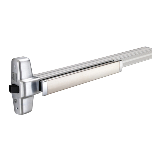
98 series, 99 series, rim exit device

Advertisement

VON DUPRIN
®

Installation Instructions

98/99
Series Rim Exit Device
®
Devices covered by these instructions:
Index:
Special tools needed:

Advertisement

Table of Contents
loading
Need help?

Need help?

Do you have a question about the 98 and is the answer not in the manual?

Questions and answers

Summary of Contents for Von Duprin 98

  • Page 1: Installation Instructions

    VON DUPRIN ® Installation Instructions 98/99 Series Rim Exit Device ® Devices covered by these instructions: Index: Special tools needed:...
  • Page 2: Screw Chart

    SCREW CHART...
  • Page 3: Preparation Chart

    PREPARATION CHART Go to instructions on next page before using preparation chart *End cap bracket - 2 holes Center case - 4 holes Center case - 2 support holes (LHR opposite) #825 Sex bolts (2) required Door cut-outs CUT-OUT FOR 99-2 “DOUBLE CYLINDER” OPTION 11/16”...
  • Page 4 Draw horizontal device and Align strike on C and mark strike center line (C ). the two slotted holes. (LHR opposite) 499F strike, Position template against strike Prepare 2 holes and install and on C and mark door. a screw thru each slot.
  • Page 5 If using an outside cylinder, check NL Prepare lock side of door drive screw and install tailpiece guide. for device and trim. NL drive screw Note: When the NL drive screw is left in back of device, the outside cylinder will function only as a Night Latch.
  • Page 6 Install 2 support screws, and center Adjust and secure strike. case cover.
  • Page 7: Optional Equipment

    OPTIONAL EQUIPMENT CD (CYLINDER DOGGING) 1. Remove mortise cylinder cam and reinstall in reverse (Figure 1). 2. Insert key and rotate cam to install the cylinder to the cover plate (Figure 2). 3. Remove key to slide cover plate in position in the mechanism case.
  • Page 8 OPTIONAL EQUIPMENT EL WIRING Troubleshooting solenoid operation EL ADJUSTMENT PROCEDURE Figure 3 Figure 4  ‚  ‚ ƒ ƒ … † … † „ … ‡ … † † „ … ‡ † ƒ ƒ ƒ ƒ „ „ ƒ...
  • Page 9: Cut Device

    CUT DEVICE Measure amount to cut off device. Tape and mark area being cut. Note Cut device square. Slide anti-rattle clip into device 499F STRIKE INSTALLATION Install strike hook and Prepare and install screws Template aligns as shown. additional strike screws. through 2 strike slots.

This manual is also suitable for:

98-f9999-fCd98Cd9998-2 ... Show all

Table of Contents