Table of Contents
Advertisement
Quick Links
*931029-00*
931029-00
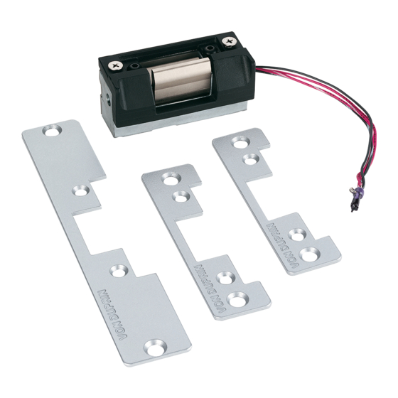
Electric Strike
1.
For lock preparation, see lock instructions.
2.
Install correct faceplate onto strike (Figure 1).
3.
Prepare frame for strike (see page 4 for dimensions).
Note: Prepare room for RCP rectifier if needed.
4.
Make sure strike operates in correct mode. Lip of fail-safe (FS) strike can be moved when strike is not powered. Lip of
fail-secure (FSE) strike cannot be moved when strike is not powered. If necessary, remove backbox cover (Figure 2) and
change strike mode by repositioning actuator (Figure 3).
Wiring must
stay in slot
Backbox cover
Figure 2
5100
#10-24 flat head
nyloc screws
4-7/8"
Standard ANSI,
Standard ANSI,
Sharp Corner
Round Corner
Figure 1
When using the electric strike in fail-secure mode, the local
authority having jurisdiction shall be consulted to assure
compliance in allowing emergency exit from the secured area.
Actuator
Fail-safe (FS) Mode
4-7/8"
7-15/16" Long,
Round Corner
NOTE
!
Actuator
Fail-secure (FSE) Mode
Figure 3
Installation Instructions
Advertisement
Table of Contents

Related Manuals for Von Duprin 5100


Summary of Contents for Von Duprin 5100
- Page 1 *931029-00* 5100 931029-00 Electric Strike Installation Instructions For lock preparation, see lock instructions. Install correct faceplate onto strike (Figure 1). #10-24 flat head nyloc screws 4-7/8” 7-15/16” Long, 4-7/8” Standard ANSI, Standard ANSI, Round Corner Sharp Corner Round Corner Figure 1 Prepare frame for strike (see page 4 for dimensions).
- Page 2 When using 12 VAC or 24 VAC power, install SO kit to convert AC power to DC (Figure 4). Wire strike solenoid for proper voltage (Figure 5). Caution: Do not connect 24 VDC to 12 VDC configured strike. 12 VDC Strike Wiring For DC operation, Von Duprin PS 861 and SOLENOID POWER Locknetics 593 DC series power supplies REQUIREMENTS are recommended.
- Page 3 If frame does not have built in mounting tabs, install mounting tabs supplied with strike as shown below (Figure 8). Drill four Shim strike in or out as Attach mounting tabs to Mount the two strike with two #12-24 mounting holes. mounting tabs inside needed until faceplate is screws and mark 4...
- Page 4 Strike Dimensions 5/32” radius on 4 corners 5/32” radius on 4 corners 1-1/2” 1-1/16” (Aluminum frame) 1 ” 3-23/32” 3-31/32” 2-7/16” 1-11/16” 2-1/16” 7-7/16” 1-11/16” 4-7/8” 7-15/16” C strike 4-1/8” 3-3/8” 3/32” 31/32” 5/8” 1-1/4” 31/32” L C lock and strike 23/32”...
Need help?
Do you have a question about the 5100 and is the answer not in the manual?
Questions and answers