Von Duprin 98 Installation Instructions Manual
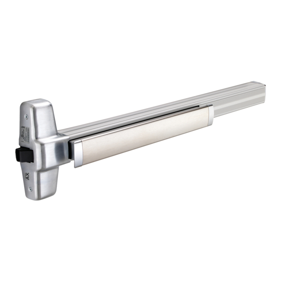
Rim exit device 98/99 series
Hide thumbs
Also See for 98:
- Installation instructions manual (8 pages) ,
- Installation instructions manual (9 pages)
Advertisement
Installation Instructions
98/99
®
Please give these instructions to building owner after device is installed
Series Rim Exit Device
Devices covered by these instructions:
98/99 Rim Exit Device
98/99-F (Fire) Rim Exit Device
CD98/CD99 (Cylinder Dogging) Rim Exit Device
98-2/99-2 (Double Cylinder) Rim Exit Device
EL98/EL99 (Electric Latch Retraction) Rim Exit Device
Special tools needed:
5/64" hex wrench
#10-24 tap
5/8" spade drill (
99-F wood door
Drill bits: #25, 1/8", 1/4",
5/16", 3/8", 13/32"
Screw chart ............................. 2
Preparation chart .................... 3
Device installation ............... 4-5
)
Optional equipment ............ 6-7
Cut device .............................. 8
499F strike installation ............ 8
© 2011 Ingersoll-Rand Company
1-877-671-7011
911373_00 Rev. 3/11_c
911373-00
Index:
Advertisement
Table of Contents

Related Manuals for Von Duprin 98


Summary of Contents for Von Duprin 98
-
Page 1: Table Of Contents
98/99 Rim Exit Device 98/99-F (Fire) Rim Exit Device CD98/CD99 (Cylinder Dogging) Rim Exit Device 98-2/99-2 (Double Cylinder) Rim Exit Device EL98/EL99 (Electric Latch Retraction) Rim Exit Device Please give these instructions to building owner after device is installed Index: Special tools needed: Screw chart ...... -
Page 2: Screw Chart
SCREW CHART #10-24 X 3/4” Metal frame Wood frame #10 X 1-1/2” Wood screw Surface mount or #10-24 X 1” Sex bolts (1-3/4” door) Sex bolts (2-1/4” door) #10-24 X 1-1/2” Surface mount (wood) #10 X 1-1/4” Wood screw - Packaged with trim - 990 Trims (1-3/4”... -
Page 3: Preparation Chart
Center case - 2 support holes #25 Drill #10-24 tap RHR shown (LHR opposite) 1/8” Drill pilot 1” deep For 98-F/99-F (fire) wood door #825 Sex bolts (2) required Door cut-outs 1/16” 3/8” Drill thru Outside cylinder applications: Mark with template and cut-out: 5/8”... -
Page 4: Device Installation
DO NOT remove NL drive screw for the following application: NL, EO, DT, TP-2, L-2, and K-2 Note: When the NL drive trims or with 98/99-2 (double cylinder). screw is left in back of device, the outside cylinder See “Screw Chart” on page 2 With “BE”... - Page 5 Install 2 Support Screws and Center Case Cover Install Tailpiece Guide Remove protective film from pushbar Tailpiece guide Center Cut tailpiece Tailpiece case if needed cover ¹⁄₂" Rotate tailpiece guide to match tailpiece Support screws (2) Install Trim (if using) and Secure Device Center Case For 98F/99F (fire rated) devices on to Door wood or composite door:...
-
Page 6: Optional Equipment
OPTIONAL EQUIPMENT CD (CYLINDER DOGGING) 1. Remove mortise cylinder cam and reinstall in reverse (Figure 1). Std. mortise cylinder 2. Insert key and rotate cam to install the cylinder to the cover plate (Figure 2). 3. Remove key to slide cover plate in position in the mechanism case. - Page 7 OPTIONAL EQUIPMENT - CONTINUED 12 AWG required for distances up to 200’ EL WIRING 14 AWG permitted for distances 0-100’ Potted Solenoid draws 16 A inrush current from PS914. circuit Solenoid Solenoid must be wired to a 900-2RS logic board: board If 900-2RS logic board, refer to instructions...
-
Page 8: Cut Device
CUT DEVICE Measure amount to cut off device. Tape and mark area being cut. Remove anti-rattle clip 1-1/2” minimum clearance (with endcap removed) Tape Cover plate (flush to pushbar) Note If 5/8” diameter wire access hole Pushbar has been predrilled in door, cut device 5/16”...
Need help?
Do you have a question about the 98 and is the answer not in the manual?
Questions and answers