Do you have a question about the 98 Series and is the answer not in the manual?
Questions and answers
THOMAS MENDOZA
March 31, 2025
HOW TO INSTALL CYLINDER ON SD SERIES CHASSIS
1 comments:
Mr. Anderson
March 31, 2025
To install a cylinder on a Von Duprin 98 Series chassis:
1. Place the collar on the cylinder. 2. Insert the cylinder into the cylinder hole in the trim. 3. Attach the back plate through the hole and align it with the grooves. 4. Use the provided cut screw to secure the back plate. 5. Check that the cylinder is centered. 6. Tighten the screws to secure the assembly. 7. Mount the rim cylinder to the cylinder bracket using #8-32 x 5/16” screws. 8. Attach the cylinder and bracket assembly to the center case using two #8-32 screws. 9. Do not over-tighten the screws.
Ensure all components are properly aligned and tightened.
Installation Instructions 98/99 
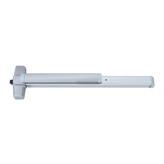
Series Rim Exit Device ® Devices covered by these instructions: 98/99 Rim Exit Device 98/99-F (Fire) Rim Exit Device CD98/CD99 (Cylinder Dogging) Rim Exit Device 98-2/99-2 (Double Cylinder) Rim Exit Device EL98/EL99 (Electric Latch Retraction) Rim Exit Device Please give these instructions to building owner after device is installed Index: Special tools needed:...
SCREW CHART #10-24 X 3/4” Metal frame Wood frame #10 X 1-1/2” Wood screw Surface mount or #10-24 X 1” Sex bolts (1-3/4” door) Sex bolts (2-1/4” door) #10-24 X 1-1/2” Surface mount (wood) #10 X 1-1/4” Wood screw - Packaged with trim - 990 Trims (1-3/4”...
PREPARATION CHART Go to instructions on next page before using preparation chart *End cap bracket - 2 holes Center case - 4 holes Surface mount Sex bolts Surface mount Sex bolts or 990 trims 1/4” Drill (device side) #25 Drill 1/4”...
Page 4
Draw horizontal device and Align strike on C and mark strike center line (C ). the two slotted holes. 299/299F Strike RHR Shown (LHR opposite) Roller *39-13/16” (against door) To finished floor For 499F strike, see back * For double doors with a cover of this instruction.
Page 5
If using an outside cylinder, check NL Prepare lock side of door drive screw and install tailpiece guide. for device and trim. NL drive screw When installing trim that has a See “Preparation Chart” on page 3 for functional lever, knob, or thumb piece drill, tap, and cut-out information AND an outside cylinder to lock and unlock the trim, remove NL drive screw...
Page 6
Install 2 support screws, Adjust and secure strike. and center case cover. 299/299F Strike Remove protective film from pushbar 3/16” Center case cover Shim for 3/16” if shimming is necessary Support screws (2) For 98F/99F (fire rated) devices on wood or composite door: #25 Drill #10-24 tap #825 sex bolts...
OPTIONAL EQUIPMENT CD (CYLINDER DOGGING) 1. Remove mortise cylinder cam and reinstall in reverse (Figure 1). Std. mortise cylinder 2. Insert key and rotate cam to install the cylinder to the cover plate (Figure 2). 3. Remove key to slide cover plate in position in the mechanism case.
Page 8
Solenoid draws 16 A inrush current from PS873. circuit Solenoid Black Solenoid must be wired to a PS873 logic board: board If 871-2 logic board, refer to Von Duprin instructions ELECTRICAL SPECIFICATIONS 941352. Voltage: 24 VDC If other 873 logic board, Current: 16 A inrush (0.3 sec.)
CUT DEVICE Measure amount to cut off device. Tape and mark area being cut. Remove anti-rattle clip 1-1/2” minimum clearance (with endcap removed) Tape Cover plate (flush to pushbar) Note If 5/8” diameter wire access hole Pushbar has been predrilled in door, cut device 5/16”...
Need help?
Do you have a question about the 98 Series and is the answer not in the manual?
Questions and answers
HOW TO INSTALL CYLINDER ON SD SERIES CHASSIS
To install a cylinder on a Von Duprin 98 Series chassis:
1. Place the collar on the cylinder.
2. Insert the cylinder into the cylinder hole in the trim.
3. Attach the back plate through the hole and align it with the grooves.
4. Use the provided cut screw to secure the back plate.
5. Check that the cylinder is centered.
6. Tighten the screws to secure the assembly.
7. Mount the rim cylinder to the cylinder bracket using #8-32 x 5/16” screws.
8. Attach the cylinder and bracket assembly to the center case using two #8-32 screws.
9. Do not over-tighten the screws.
Ensure all components are properly aligned and tightened.
This answer is automatically generated